
Modelling Decision Support Systems using Conceptual Constraints
Linking Process Systems Engineering and Decision Making Models
Canan Dombayci and Antonio Espu
˜
na
Chemical Engineering Department, EEBE, Universitat Polit
`
ecnica de Catalunya, Av. Eduard Maristany,
10-14, 08019 - Barcelona, Spain
Keywords:
Knowledge Engineering, Ontology Engineering, Decision Support Systems, Mathematical Programming,
Conceptual Constraint Domain, Process Systems Engineering.
Abstract:
This paper presents the use of a Conceptual Constraint (CC) Domain to systematize the construction of De-
cision Making Models (DMMs). The modelling systematics include the integration between the CC Domain
and production systems as well as an identification procedure which contains some steps aimed at constraint
identification using the CC Domain. The CC Domain consists of different modelling elements such as Concep-
tual Constraints (generic constraint types), Conceptual Components (pieces of a constraint), and Conceptual
Component Elements (pieces of a conceptual component that may be connected to production systems). In
this instance, the CC Domain is integrated with the Process Systems Engineering (PSE) Domain as a produc-
tion system domain. The PSE Domain contains information from the multi-level functional hierarchical in an
enterprise and it will be used to cover a wide range of scenarios related to hierarchical integration of DMMs.
In addition, an integration step between the CC and PSE Domains is illustrated. The focus of the work is
to show how these models should be developed in order to be properly integrated, and how they are used by
different functionalities with an identification procedure.
1 INTRODUCTION
Process Systems Engineering (PSE
1
) may be de-
scribed as the art of decision-making for engineering
disciplines such as design, operation, and control of
chemical, physical, and biological processes through
the aid of systematic computer based methods and op-
timization tools (Grossmann and Westerberg, 2000).
The PSE community uses conceptualized modelling
in order to support systematic problem solving. Re-
cently, ontological modelling has been used to build
semantic structures, while Knowledge Engineering
(KE) foundations have been implemented as a new
modelling paradigm with the purpose of supporting
chemical process engineering (Morbach et al., 2007),
managing chemical batch processes (Mu
˜
noz et al.,
2010), data reconciliation (Roda and Musulin, 2014),
pharmaceutical product engineering (Remolona et al.,
2017), etc. In addition, there are other communities
working on similar issues that PSE attempts to solve
(e.g. planning & scheduling (Palacios et al., 2016),
failure prevention (Rajpathak et al., 2001)).
Ontologies use semantic structures, which aim to
1
Complete list of abbreviations are given in Table 1.
Table 1: Abbreviations.
Abbr Explanation
BaPron Batch Process Ontology
CC Conceptual Constraint
CComp Conceptual Component
CCompEl Conceptual Component Element
DMM Decision Making Model
DSS Decision Support System
ISA88 Batch Control Standard from Inter-
national Society of Automation
KE Knowledge Engineering
PSE Process Systems Engineering
represent an abstraction of a domain as well as sup-
port KE applications in many applications such as
Decision Support Systems (DSSs), Artificial Intelli-
gence, etc. DSSs contain a big range of function-
alities and connections to different domains (Shim
et al., 2002). While the conceptualization of De-
cision Making Models (DMMs) in information sys-
tems is crucial, its systematization remains an open
research field. There are many types of DMMs that
may be used rather than mathematical programming
(e.g. dynamic programming or simulations). Addi-
Dombayci C. and EspuÃ
´
sa A.
Modelling Decision Support Systems using Conceptual Constraints - Linking Process Systems Engineering and Decision Making Models.
DOI: 10.5220/0006485201470154
In Proceedings of the 9th International Joint Conference on Knowledge Discovery, Knowledge Engineering and Knowledge Management (KEOD 2017), pages 147-154
ISBN: 978-989-758-272-1
Copyright
c
2017 by SCITEPRESS – Science and Technology Publications, Lda. All rights reserved

tionally, the PSE Domain structure may vary from
multi-level hierarchical systems to other systems (e.g.
multi-scale systems, systems of systems, interwoven
systems). However, this work considers (i) multi-
level hierarchies in order to model the information
presented in production systems and (ii) DMMs based
on mathematical programming.
2 BACKGROUND
2.1 DMMs Related Background
The DSSs based on mathematical programming, have
been a topic of great interest in recent years; more-
over, mathematical programming has been used to
tackle modelling issues in the solution stage of
decision-making procedures.
Mathematical programming has been used to sup-
port strategic, tactical, and operational decisions
based on the production and distribution activities of
a production system. However, a hierarchical integra-
tive approach can represent an alternative to mathe-
matical programming. Under this approach, relevant
information is aggregated to develop proper mathe-
matical models (Bradley et al., 1977). DMMs based
on mathematical programming mainly consist of fol-
lowing items (Williams, 2013):
Sets: include indices for certain classes of variables,
indicating the size/complexity of the model to be
solved.
Parameters: coefficients of the model (defined as a
scalar or matrix).
Variables: decision variables of the model.
Constraints: relation between parameters and vari-
ables which have to be considered to ensure feasi-
bility of the proposed decision.
Objective: expression to be minimized or maxi-
mized during the decision-making procedure.
Traditionally, DMMs in production systems are con-
structed manually according to the existing data and
problem features (e.g. time horizon, decision vari-
ables and parameters, definition of constraints, and
selection of objective functions). However, there is
a lack of generic systematics for the construction of
such models (Gani and Grossmann, 2007).
The previous classification of the DMM elements
is generally used for demonstration purposes and the
systematic development of general formulations aim-
ing to solve a domain problem in a generic way. How-
ever, the connections among constraints and other ele-
ments (such as sets, parameters and variables) are not
straightforward inside a formulation and these con-
nections do not appear among different formulations.
Some of the main types of constraints are (Williams,
2013):
• productive capacity constraints or manpower,
• raw material availability,
• marketing demands and limitations,
• balance constraints (e.g. energy and material),
• quality stipulations,
• hard and soft constraints that can be violated or
can be violated by means of an extra cost,
• chance constraints related to probability, and
• simple and generalized upper bounds.
These constraints are generally used to create the
DMMs by selecting and revising according to the
analysis of the process. However, this constraint clas-
sification is not enough to support the automated con-
struction of DMMs. For this reason, the CC Domain
has been proposed and patterns of constraints are sug-
gested to be used during the conceptual modelling of
the CC Domain (Dombayci and Espu
˜
na, 2018).
2.2 PSE Related Background
Over the last decades, ontology development and
usage have been important subjects in applications
related to KE, Artificial Intelligence, Natural Lan-
guage Processing, etc. In the case of PSE, the ex-
tensive exploitation of general PSE ontologies to sup-
port the development and maintenance of models, as
well as their integration and coordination with sys-
tem/models from the related areas/domains is object
of growing interest (Morbach et al., 2007, Mu
˜
noz
et al., 2010,Roda and Musulin, 2014,Remolona et al.,
2017). The research on these application has sup-
ported the management of the great amount of infor-
mation related to the problem statement and the new
exploitations has supported development and (re)used
of conceptual models.
The need of a generic model to support PSE ac-
tivities has been recognized from the very beginning
of the PSE. A reference model for computer inte-
grated manufacturing has been developed (Williams,
1989) as a conceptual representation of the system
and it has evolved to a widely used ANSI standard
on batch control as ISA88 (ISA, 2010). The interdis-
ciplinary area of PSE and KE, different methodolo-
gies have been developed which centre on the creation
of domain knowledge. The batch process ontology
(BaPrOn) is built from the concepts of a batch control
standard (ISA88) and used in order to monitor and

control the scheduling in a pilot plant (Mu
˜
noz et al.,
2010). The intention of not just communicating but
also supporting the integration of different software
tools and exploitation of plant database information
are also considered (Mu
˜
noz et al., 2012). Addition-
ally, integration between planning and scheduling ac-
tivities in batch processes have been modelled using
ontology modelling techniques (Vegetti and Henning,
2015).
The ISA88 standard has supported the background
of the PSE Domain with the main model represen-
tations: process, procedural, and physical models.
These models contain the hierarchical representation
of production systems and connections between these
model elements. The ISA88 has also been used to
build another ontology which is a result of a system-
atic approach for the construction of domain ontolo-
gies (Dombayci et al., 2015). The methodology has
two main steps: (i) a procedure for extraction of con-
cepts and class-subclass pairs from a technical docu-
ment (Farreres et al., 2014) and (ii) a systematic pro-
cedure for solving inconsistencies and contradictions
arisen from the first step. These two steps constitute
a semi-automatic ontology construction methodology.
In addition, the semi-automatic procedure produces
a list of suggestions for improving technical docu-
ments by analysing the conceptual model that is semi-
automatically constructed from the source (Dombayci
et al., 2017). But more importantly basic concepts re-
lated to the standard are extracted and the multi-level
hierarchical structure of ISA88 has been introduced
with its concept and relations.
3 METHODOLOGY
The basic structure underlying the system and con-
cepts in CC Domain is detailed in Section 3.1. The in-
tegration of PSE Domain is suggested to enhance the
CC Domain functionalities and the integration using
ontological elements such as concepts, object prop-
erties, data properties, and instances are presented in
Section 3.1.
In addition, the general steps are introduced re-
lated to the functionalities that can be used to demon-
strate the domain applications is detailed in Section
3.3. The identification procedure related steps are in-
troduced in Section 3.3.1 and the last step related to
the identification is presented in Section 3.3.2 with a
case study.
3.1 The Conceptual Constraint Domain
The conceptualization of DMMs in a Conceptual
Constraint (CC) Domain is important for the auto-
mated building of DMMs using a knowledge-based
system. Therefore, the construction of integrated on-
tological models and their usage in order to provide
conceptualized models for the CC Domain function-
alities are studied. This work demonstrates the mod-
elling, the integration, and the connection of DMMs
and knowledge models from the PSE point of view in
order to maintain a complete DSS. The main aim is
to link these two domains together in order to develop
systematic strategies for supporting decision-making
procedures.
The basic design of the CC Domain is the abstrac-
tion of the DMMs that are constructed through con-
straints, sets, parameters, and variables; ontological
modelling techniques are adopted to model the do-
main with ontological model elements. There are 3
main types of concepts that belong to this ontological
model: the Conceptual Constraint (CC), the Concep-
tual Component (CComp), and the Conceptual Com-
ponent Element (CCompEl). A relational demonstra-
tion of these elements is shown in Figure 1 and this
figure is adapted for the case study in Figure 5(see
Section 3.3.2).
The CCs represent the semantic models of the
main types of constraints, which are built from the
main publications containing DMMs related to pro-
duction systems. The first step is to build a tax-
onomy that captures the main constraints such as
’BalanceCC’, ’ResourceAllocationCC’, ’TimingCC’,
’SizingCC’, ’SequencingCC’, and ’EconomicalCC’.
Then, the taxonomy is detailed considering these
main types of constraints, as depicted in Figure 2.
The CCs are separated into fundamental constraint
types, then the CC taxonomy is deepened with sub-
classes. For instance, the ’BalanceCC’ has the ’Mate-
rialBalanceCC’ and the ’EnergyBalanceCC’ concepts
as subclasses, which share the balancing as a com-
mon element as well as the same CComps such as the
’StoredAmount’. Depending on characteristics of the
CC the ’StoredAmount’ CComp may change from en-
ergy to material and the CCompEls that are connected
to the PSE Domain change from a concept connected
to an energy to material.
The CComps represent the concepts that construct
the CCs. The partOf relation connects CCs and
CComps in order to construct the patterns of each CC;
each CComp may be connected to more than one CC.
The elements in the DMMs (parameters, variables)
are represented through CComps. The representation
of these elements is straightforward, for example, the
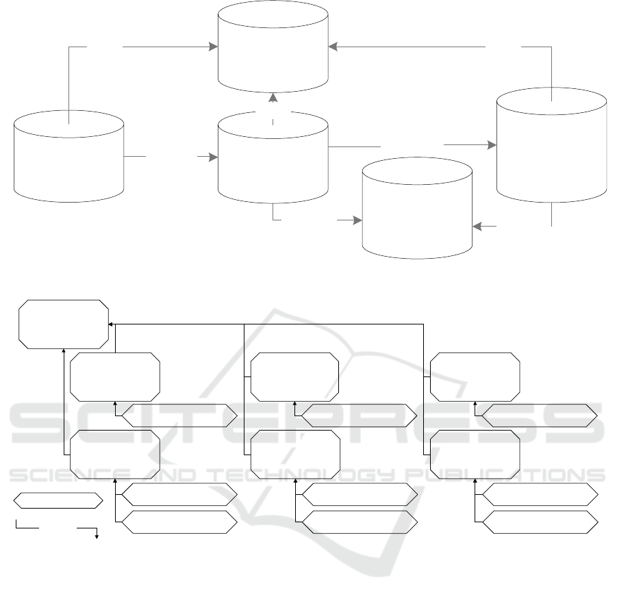
Conceptual
Constraint Domain
Conceptual
Component
Conceptual
Constraint
Conceptual
Component
Element
partOf
hasCompEl
Integrated object
and data properties
(CC and PSE
Domains)
connected
hasComp
connected
partOf
partOf
Figure 1: Relations in the CC Domain.
Resource
Allocation
CC
Sizing CC Balance CC
Physical Model
Allocation CC
Sequencing
CC
Material Balance CC
Sequence Dependent
Changeover CC
Time Matching CC
Sales Sizing CC
Production Sizing CC
Timing CC
Worker Allocation CC
Economical
CC
Total Cost
Economical CC
Energy Balance CC
Conceptual
Constraint
Concept
is-a
(taxonomic
relation)
Figure 2: Part of the Conceptual Constraint Taxonomy in the CC Domain.
CComp ’ProducedMaterial’ may present a variable.
On the other hand, the ’ProducedMaterial’ CComp
may present an expression that is constructed from a
variable and a parameter. For instance, the ’Produced-
Material’ may present a proportion (parameter) of the
input material (variable).
The CCompEls represent the connections of the
CComps to the different concepts, which appear in
the conceptual domain (i.e., the PSE Domain) in order
to carry out the applications. Therefore, the CComps
are connected to the CCompEls for the definition of a
DMM. For instance, the ’ProducedMaterial’ CComp
may be defined with a unit in one DMM and with a
process cell in another DMM.
3.2 Integration of the CC and PSE
Domains
The Material Balance CC example is depicted in Fig-
ure 3 containing the ’ProducedMaterial’ CComp and
its relations. Two separate sections are used for the
CC and PSE Domains. The CC Domain section the
CCs are connected to CComps. In the CC Domain
section the CCs are connected to CComps, while the
CCompEls are connected to their specific concepts
in the PSE Domain. Then, each CComp is con-
nected to the CCompEls that exist in PSE Domain.
The example shows that ’a MaterialBalanceCC has
ProducedMaterial as a CComp’ and ’ProducedMate-
rial CComp may be linked to 4 different CCompEls
depending on the DMM-formulation (F1, F2, F3,
F4). These formulations represent different DMMs
Conceptual Constraint Domain
Process Systems Engineering Domain
Material
Balance CC
Consumed
Material
Produced
Material
Currently Available
Material
Previously
Available Material
Procedural
Model
Physical Model
Enterprise
Process Cell
Unit
linked of CCompEl
in F1
linked of
CCompEl in F2
linked of
CCompEl in F3
has Process Cell
has Enterprise
has Unit
linked of
CCompEl in F4
is part of
is part of
is part of
has CComp
Concept
Object Property
Concept
Figure 3: Connections between CC and PSE Domains.
in the multi-level hierarchies. However, these ele-
ments appear in the PSE Domain where another tax-
onomy exists. In this sense, the ’PhysicalModel’
concept has different sub-concepts and the ’Procedu-
ralModel’ is connected to these elements of physical
model through the ’ProceduralModel’. In addition, a
’partOf’ relation is depicted in the PSE Ontology that
contains the hierarchical model representation of an
enterprise.
3.3 Functionalities
The integration between the CC and PSE Domains
brings these domains together for the applications; for
example, extending the DMMs arisen in a specific hi-
erarchical level to another level or using an already
constructed DMM for a specific problem instead of
constructing a new DMM from the beginning. In this
section, 5 steps required for the constraint prediction
application are explained. The first 3 steps are the
steps that are general steps to be used in many func-
tionalities include parsing and matching from sets, pa-
rameters, variables and equations to the CC Domain
elements. Afterwards, Section 3.3.1 introduces the
fourth step that is a network construction from the
DMMs. The fourth step is required for the explana-
tion of the functionality explained in Step 5 in order
to predict the CC type.
Here, the basic steps required in order to identify a
constraint within the framework, starting from a con-
straint that is written using a high level syntax are ex-
plained:
Step 1: The first step is to parse the source con-
taining a constraint that is to be identified within the
pre-determined structure. The DMM equations are
decomposed into elements by automatically parsing a
source file into set, variable, parameter and equation
inputs.
Step 2: The DMM elements found in the previous
step are matched in a list of CComps and CCompEls.
For instance, set inputs are matched to the CCompEls,
whereas parameter and variable inputs are matched to
the CComps. The matching step can be performed in
two ways: (i) direct user interaction and/or (ii) based
on a dictionary that stores user decisions for previous
matching procedures. The information coming from a
user interaction or the dictionary are used in the Step 3
for matching the connections between equations. In-
puts are stored in a structure contains IDs, explana-
tions, list of parameters and corresponding identified
fields as depicted in Figure 4(a).
Step 3: The equation inputs are connected to the CC
Domain elements (CComps and CCompEls) through
the set, parameter and variable inputs. These connec-
tions are stored as ’equation connections to the ele-
ments’ in enriched equation input structure as illus-
trated in Figure 4(b).

Table 2: Connections of Equation 1.
Symbol Explanation from the source paper CC Domain connec-
tion (CComp)
PSE Domain connection
(CCompEl)
K Set: energy storage systems (k ∈ K) PhysicalModel
TRH Set: time intervals included in the current
prediction horizon (t ∈ T RH)
Time Model
η
in
k
Parameter: charging efficiency of energy
storage system k
ChargingEfficiency PhysicalModel
η
out
k
Parameter: discharging efficiency of en-
ergy storage system k
Discharging Effi-
ciency
PhysicalModel
Ld
k,t
Variable: energy supplied to load system
k during interval t (kW h)
SuppliedDemand PhysicalModel, TimeModel
SP
k,t
Variable: energy supplied by storage sys-
tem k during interval t (kW h)
SuppliedDemand Physical Model, TimeModel
SE
k,t
Variable: electricity storage level of sys-
tem k at the end of the interval t (kW h)
CurrentlyAvailable
Amount
PhysicalModel, TimeModel
Parameter Input
ID
explanation
listOfParameters
IdentifiedField
ID
Individual
IdentifiedQuery
(a) Parameter Input.
Equation Input
ID
listOfEquation
equationExplanation
equationConnectionToELements
(b) Equation Input.
Figure 4: Enriched Input Structures.
3.3.1 The Network Construction
This section illustrates how constraint identification
is managed in the domain by exploiting the already
established connections between the CC and PSE Do-
mains. The Step 4 introduces complete and consistent
DMMs containing known constraints as input.
Step 4: A network is built through the CC Do-
main using the CC Domain model information that
was previously developed using the Machine Learn-
ing Toolbox of Matlab. A Bayesian network is build
using CComp and CCompEls as features of each class
(CCs) so that the network can be used to predict the
type of the introduced constraint.
3.3.2 The Constraint Identification and the Case
Study
The Step 5 is the core step that uses the general steps
(1-3) and network construction and predicts the type
of the constraint.
Step 5: This step combines all the connected-
identified elements of an equation and the CC Domain
network in order to predict the type of the CC in the
domain. As a result, a set of probability values are
received corresponding to the unknown constraint.
Constraint Identification Case Study: In order to
demonstrate the constraint identification, an energy
balance equation from an energy supply and demand
planning DMM is used (Silvente et al., 2015):
SE
k,t
= SE
k,t−1
+ η
in
k
∗ Ld
k,t
−
SP
k,t
η
out
k
, ∀k ∈ K, t ∈ T RH
(1)
Equation 1 has been parsed and paired through
the same procedures explained in Section 3.3 (Step
1-3). Table 2 shows the full list of symbols, nomen-
clature explanations of these symbols from the source
paper and connected elements in the CC and PSE Do-
mains. The connected elements of the sets (K and
TRH) are the CCompEls and the rest of the symbols
belong to the CComp type of concepts. Accordingly,
while sets have the same concept in the PSE Domain
column, the CComps (variables and parameters) have
connected CCompEls.
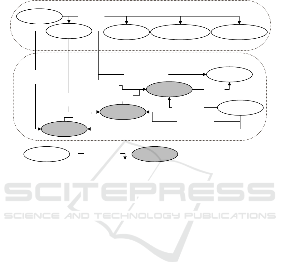
Relations in the CC Domain are shown in Figure
5. The connections of elements in the CC Domain
are depicted with the example including the relations
between the models. The demonstrative example is
used as an instance of the domain where the parsed
and matched information are shown. For instance,
Equation 1 is depicted as a ’BalanceCC’ since there
are many CComp connections with the hasCompo-
nent relation. After the implementation of Step 5, the
prediction probabilities are obtained as in Figure 6.
As a result, the constraint in Equation 1 is predicted as
a ’BalanceCC’ with 0.64 probability and an ’Energy-
BalanceCC’ with a probability of 0.07 (the remaining
predictions are less than 0.03); note that the classifi-
cation is made by evaluating 41 types of CCs. The
domain model can be continuously improved as new
formulations are reviewed. The results are expected to
have higher probability value while the domain model
Conceptual Constraint
Domain
Conceptual Component:
Currently Available
Amount
Conceptual Constraint:
Balance Constraint
Conceptual Component
Element:
Procedural Model &
Time Model
partOf
hasCompEl
hasProcedure,
hasTimeInterval
and
#currentlyAvailable
Amount
connected
hasComp
connected
partOf
partOf
,
SE
kt
&kt
Previously Stored
Amount
,1
SE
kt
,
, , 1 ,
SE =SE + Ld - , k,t TRH
kt
in
k t k t k k t
out
k
SP
hasComp
Instance of a
concept
Figure 5: Connections of Conceptual Models with the Example.
Balance CC, 0.64
Energy Balance CC, 0.07
0.03
0.00
0.10
0.20
0.30
0.40
0.50
0.60
Probability
Conceptual Constraints
Contraint identification results of the input 'equation'
Figure 6: Result of Identification of Equation 1 (x-axis rep-
resents each CC and y-axis gives the probability of being in
the same CC).
is getting more accurate and larger in terms of differ-
ent formulations introduced.
The purpose of the identification procedure is not
only to predict the type of the constraint but also to
fully identify the constraint connections to the do-
main. Therefore, all connections related to the con-
straint have been introduced to the system. The con-
straint is defined as a Balance CC with the connec-
tions to the specific physical model used but it can
be expected to be used in any extension procedure by
simply changing the connections in the PSE Domain.
4 CONCLUSIONS
This paper has presented a framework aiming to
support construction of Decision Making Models
(DMMs) using the Conceptual Constraint (CC) Do-
main. The construction of DMMs requires a proce-
dure that involves a DMM abstraction and the inte-
gration with domains connected to the main purpose.
The CC Domain contains the generic/abstract model
information of DMMs and conceptualized patterns of
constraints. Therefore, the CC Domain is adequate
for representation of constraints. A production system
domain, the Process Systems Engineering (PSE) Do-
main, containing multi-level hierarchies, is selected to
be integrated into the CC Domain to illustrate its main
features. The paper presented a procedure that allows
the identification of constraints in the CC Domain.
The procedure was demonstrated using an example
from energy systems in order to show some aspects
of the framework. This identification procedure may
be used as the basis of an integration procedure that
integrates DMMs at multi-level hierarchies. The CC
Domain is continuously improved by considering dif-
ferent DMMs; however, it is important to consider au-
tomated processing of the DMMs to improve the CC
Domain. Further developments should be devoted to
explore the potential use of classification algorithms.
ACKNOWLEDGEMENTS
Financial support from the Spanish Ministry of Econ-
omy and Competitiveness and ERDF (ECOCIS:
DPI2013-48243-C2-1-R), and AGAUR (2014-SGR-
1092-CEPEiMA and grant FI) is fully appreciated.

REFERENCES
Bradley, S. P., Hax, A. C., and Magnanti, T. L. (1977). Ap-
plied mathematical programming. Addison-Wesley
Publishing Company.
Dombayci, C. and Espu
˜
na, A. (2018). Building De-
cision Making Models Through Conceptual Con-
straints: Multi-scale Process Model Implementations.
In Fink, A., F
¨
ugenschuh, A., and Geiger, M.-J., ed-
itors, Operations Research Proceedings 2016, pages
77–83. Springer International Publishing.
Dombayci, C., Farreres, J., Rodr
´
ıguez, H., Espu
˜
na, A., and
Graells, M. (2017). Improving automation standards
via semantic modelling: Application to ISA88. ISA
Transactions, 67:443–454.
Dombayci, C., Farreres, J., Rodr
´
ıguez, H., Mu
˜
noz, E.,
Cap
´
on-Garc
´
ıa, E., Espu
˜
na, A., and Graells, M. (2015).
On the Process of Building a Process Systems Engi-
neering Ontology Using a Semi-Automatic Construc-
tion Approach. In Computer Aided Chemical Engi-
neering, volume 37, pages 941–946.
Farreres, J., Graells, M., Rodr
´
ıguez, H., and Espu
˜
na, A.
(2014). Towards Automatic Construction of Domain
Ontologies: Application to ISA88. In Kleme
ˇ
s, J. J.,
Varbanov, P. S., and Liew, P. Y., editors, Proceedings
of the 24th European Symposium on Computer Aided
Process Engineering, pages 871–876. Elsevier.
Gani, R. and Grossmann, I. (2007). Process systems engi-
neering and CAPE - what next? Proceedings of the
17th European Symposium on Computer Aided Pro-
cess Engineering, pages 1–5.
Grossmann, I. E. and Westerberg, A. W. (2000). Research
challenges in process systems engineering. AIChE
Journal, 46(9):1700–1703.
ISA (2010). Batch Control, Part 1: Models and Terminol-
ogy, ANSI/ISA-88.01-2010. ISA Committe.
Morbach, J., Yang, A., and Marquardt, W. (2007).
OntoCAPE-A large-scale ontology for chemical pro-
cess engineering. Engineering Applications of Artifi-
cial Intelligence, 20(2):147–161.
Mu
˜
noz, E., Cap
´
on, E., La
´
ınez, J., Espu
˜
na, A., and Puig-
janer, L. (2012). Ontological framework for inte-
grating environmental issues within sustainable enter-
prise: Enhancing enterprise decision-making. KEOD
2012 - Proceedings of the International Conference on
Knowledge Engineering and Ontology Development,
pages 385–388.
Mu
˜
noz, E., Espu
˜
na, A., and Puigjaner, L. (2010). Towards
an ontological infrastructure for chemical batch pro-
cess management. Computers & Chemical Engineer-
ing, 34(5):668–682.
Palacios, L., Lortal, G., Laudy, C., Sannino, C., Simon, L.,
Fusco, G., Ma, Y., and Reynaud, C. (2016). Avionics
Maintenance Ontology Building for Failure Diagnosis
Support. In Proceedings of the 8th International Joint
Conference on Knowledge Discovery, Knowledge En-
gineering and Knowledge Management (Ic3k), vol-
ume 2, pages 204–209. SCITEPRESS - Science and
and Technology Publications.
Rajpathak, D., Motta, E., and Roy, R. (2001). A generic task
ontology for scheduling applications. In International
Conference on Artificial Intelligence (IC AI’2001),
Las Vegas, USA.
Remolona, M. F. M., Conway, M. F., Balasubramanian,
S., Fan, L., Feng, Z., Gu, T., Kim, H., Nirantar,
P. M., Panda, S., Ranabothu, N. R., Rastogi, N., and
Venkatasubramanian, V. (2017). Hybrid ontology-
learning materials engineering system for pharmaceu-
tical products: Multi-label entity recognition and con-
cept detection. Computers & Chemical Engineering.
Roda, F. and Musulin, E. (2014). An ontology-based
framework to support intelligent data analysis of sen-
sor measurements. Expert Systems with Applications,
41(17):7914–7926.
Shim, J., Warkentin, M., Courtney, J. F., Power, D. J.,
Sharda, R., and Carlsson, C. (2002). Past, present,
and future of decision support technology. Decision
Support Systems, 33(2):111–126.
Silvente, J., Kopanos, G. M., Pistikopoulos, E. N., and
Espu
˜
na, A. (2015). A rolling horizon optimization
framework for the simultaneous energy supply and
demand planning in microgrids. Applied Energy,
155:485–501.
Vegetti, M. and Henning, G. (2015). An Ontological Ap-
proach to Integration of Planning and Scheduling Ac-
tivities in Batch Process Industries. In Computer
Aided Chemical Engineering, volume 37, pages 995–
1000.
Williams, H. P. (2013). Model Building in Mathematical
Programming. Wiley, 5th edition.
Williams, T. J., editor (1989). A Reference Model for Com-
puter Integrated Manufacturing (CIM): A Description
from the Viewpoint of Industrial Automation. Instru-
ment Society of America.
