
An Offline Outdoor Navigation System with Full Privacy
Prakhar Kaushik
1
, Vishal Saraswat
2
and Francesco Buccafurri
3
1
Amity University, Delhi, India
2
Indian Statistical Institute, Kolkata, India
3
DIIES, University of Reggio Calabria, Reggio Calabria, Italy
Keywords:
Privacy, Positioning Systems, Smartphone.
Abstract:
GPS navigation systems are a potential threat to user privacy in case of curious providers, espionage and many
other aspects. Users tend to place blind trust into GPS applications without realizing the ease at which the GPS
can be spoofed or their position compromised via either the hardware or software. Thus, when a high level
of privacy assurance is required, the GPS should be completely switched off. This paper presents an efficient
method, a smartphone-based alternative solution, for an outdoor offline navigation system, which works in
the absence of GPS, wireless, and cellular signals. The proposed approach exploits the various digital and
mathematical resources present to use DEM data and sensor data to minimize errors in the calculated position
data.
1 INTRODUCTION
The development of Global Positioning Systems
(GPS), Mobile triangulation, etc. have led a revolu-
tion in outdoor navigation. There are several tech-
niques employed to find the position of the subject
with satellite signals. Inertial navigation has been
used since some time due to its applications in avi-
ation and military purposes with specific reference to
missile navigation. In inertial navigation, measure-
ments provided by the inertial sensors such as gyro-
scopes and accelerometers. Pedometer systems count
steps by monitoring the vertical acceleration using a
piezo electric accelerometer. Despite the voluminous
research in personal and pedestrian navigation (Kim
et al., 2004; Feliz Alonso et al., 2009; Ho et al., 2016),
a personalized positioning system which works with-
out any type of wireless, GPS or cellular signal is still
not publicly available despite the obvious demand.
We encounter such conditions while trekking and hik-
ing through mountains and forests. Another use case
is whenever a user (consider for example the intel-
ligence domain) wants to have fully secret naviga-
tion and needs to turn-off all the wireless functions
of the smartphone. In those cases, even the use of
only the GPS receiver could be not a solution be-
cause even though GPS is a self-positioning system,
its availability in telematics systems enables various
privacy abuses both in real-time and retrospect (Iqbal
and Lim, 2010; Alzantot and Youssef, 2012). Even a
passive GPS antenna with path logging off is suscep-
tible to spoofing attacks as well as remote GPS data
acquisition as long as they are connected to the net-
work. Further, the hardware itself can be manipulated
in order to leak position data. With increasing num-
ber of mobile applications and software directly or
indirectly collecting positioning data from our smart-
phones, it has become relatively easy for a third party
to track our positions.
We introduce a new algorithm which may be capa-
ble of resolving the aforementioned problem in terms
of an off-line navigation system. There have been ef-
forts to solve a similar problem, but in the context
of an indoor environment or a dense human interac-
tive environment (for example, a trade fair). This pa-
per presents a solution for outdoor environment with
sparse human activity.
We propose a positioning system which can work
with off-line smartphones, provided, the maps of the
territory are previously downloaded. Moreover, col-
lected data are only differential w.r.t. a given posi-
tion, so they are inherently less sensitive than GPS
data. The positioning is then really performed when-
ever an initial checkpoint (starting point set in the ap-
plication) is mapped to a point of a map. We believe
that a smartphone which is not transmitting or receiv-
ing any kind of wireless signal is certainly compara-
tively more safe than a GPS in terms of privacy.
Kaushik, P., Saraswat, V. and Buccafurri, F.
An Offline Outdoor Navigation System with Full Privacy.
DOI: 10.5220/0006473800950101
In Proceedings of the 14th International Joint Conference on e-Business and Telecommunications (ICETE 2017) - Volume 6: WINSYS, pages 95-101
ISBN: 978-989-758-261-5
Copyright © 2017 by SCITEPRESS – Science and Technology Publications, Lda. All rights reserved
95

Figure 1: Inertial Navigation System.
2 IMPORTANT DEFINITIONS
2.1 Inertial Navigation
Inertial navigation (Woodman, 2007) (Figure 1) is
a self-contained navigation technique in which mea-
surements provided by accelerometers and gyro-
scopes are used to track the position and orientation
of an object relative to a known starting point, orienta-
tion and velocity. Inertial measurement units (IMUs)
typically contain three orthogonal rate-gyroscopes
and three orthogonal accelerometers, measuring an-
gular velocity and linear acceleration respectively.
For tracking the position, we use the accelerome-
ter data A
f
(t) = (a
x
f
(t),a
y
f
(t),a
z
f
(t))
T
and project it
to global frame of reference: A
g
= CA
f
. This data is
then integrated to get velocity and displacement.
v
g
(t) = v
g
(0) +
Z
t
0
a
g
(t) −g
g
dt
s
g
(t) = s
g
(0) +
Z
t
0
v
g
(t)dt .
2.2 Directional Trail
The directional trail (Constandache et al., 2010) is de-
fined as a series of last N compass readings and an
associated set of displacements between them. The
compass readings are collected with a time separa-
tion of 1 second. A compass trail is a tuple C
N
=
(c
0
,c
1
,c
2
...c
N
) where c
0
is the compass reading at
the user’s estimated current location, c
1
is the pre-
vious reading, and so on. The accelerometer based
displacements between compass readings is the tuple
D = δ
0
,δ
1
,...δ
−N+1
where the user walked a distance
of δ
j
between two compass measurements, c
j−1
and
c
j
.
2.3 Sensor Fusion
Sensor Fusion (Elmenreich, 2002) refers to the com-
bination of two or more data sources, to produce bet-
ter data, better representation, improve signal to noise
ratio, etc. Gyroscope data may be fused with that of
magnetometer to smoothen the noise in the gyroscope
data. Similarly, gravity data may be fused with ac-
celerometer data in order to get only acceleration val-
ues for each axis. Sensor data may also be fused with
an absolute positioning system to provide a better and
accurate data.
2.4 Error Sources and Analysis
There are five major error types (Woodman, 2007)
while dealing with accelerometer and gyroscope —
white noise, temperature, calibration, bias and bias
instability. For accelerometer, double integration of
bias leads to a quadratically increasing positional er-
ror while in gyroscope there is steadily increasing an-
gular error.
2.5 Countermeasures
Two popular countermeasures against the above-
mentioned errors are:
Sensor Fusion. Raw data from two or more sensors
is processed through sensor fusion methodology
to obtain relatively more accurate readings.
Modelling and Subtraction of Bias. The system is
kept stationary for a period of time and the bias
observed is then modelled and subtracted from the
final readings.
3 RELATED WORK
(Zhou, 2016) studied pedestrian dead reckoning and
its exploitation of the cyclical movements of the hu-
man body and provided algorithms to detect the foot
fall and estimate the stride length of the subject. A
reference to a relationship between z-axis acceleration
and step length is also provided. A Simple Moving
Average (SMA) preprocessing algorithm is proposed
for smoothing the acceleration data.
(Yun et al., 2007) provided a method for tracking
WINSYS 2017 - 14th International Conference on Wireless Networks and Mobile Systems
96
2D and 3D position of human movement using a self-
contained inertial/magnetic sensor module and pre-
liminary experimental results for various human mo-
tion including straight line walking, circular walking,
side stepping, backward walking, running, and climb-
ing stairs. They use a time heuristic and z-axis accel-
eration data to detect stance phase (two phases dur-
ing walking: stance phase (60%) and swing phase
(40%)). For angular measurements also, the x-axis
angular rate is near zero (for foot placed sensor) dur-
ing the stance phase. For straight line walking, the
average measurement error was recorded to be 5.5%
which was attributed to the presence of magnetic in-
terference in indoor environments. For outdoor con-
ditions, an average measurement error of 1.3% was
observed. The maximum error for outdoor straight
line running was recorded to be within 4.75%. Circu-
lar walking gave a distance estimation error of 1.8%.
(Constandache et al., 2010) presents a scheme,
CompAcc (Figure 2), to counter the cons of position-
ing systems like GPS, War Driving, GSM triangula-
tion, etc. The authors of this paper also had similar
motivations and objectives as us and seem to have had
similar train of thought, but they do not provide a fully
offline system as we do.
Figure 2: CompAcc.
Basically, a map tile containing the path informa-
tion of the area is acquired from the server. Using the
AGPS initial location, the system creates path signa-
tures with the initial location as its centre. A direc-
tional trail for the subject is created using (distance,
orientation) tuple. As a fall-back mechanism, Com-
pAcc allows the search window to cover at most a sin-
gle intersection at a point of time in the map tile. The
errors which aggregate during this period are reset by
the detection of directional change by the sensors. In
case the error grows too big, an AGPS request is sent
for location data reset.
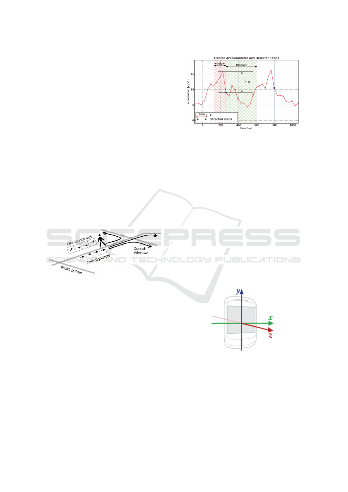
(Link et al., 2013) is similar to our topic, though,
in an indoor navigation concept. They employ a two-
stage approach: (1) step detection and step heading
estimation, and (2) match detected steps onto the ex-
pected route from the source to the destination using
sequence alignment algorithms.
Basically, a pre-designed floor plan is used to
identify probable paths between the source and the
Figure 3: Step Detection.
destination. OpenStreetMap is used as a map ma-
terial. For step detection (Figure 3), the z-axis ac-
celerometer data is used with a time out window to
avoid false step detections. A step is detected if there
is a difference of at least p = 2m/s
2
on the low pass
filtered z-axis of the accelerometer.
4 EXPERIMENTAL SETUP
All the sensor and raw data was collected initially on a
Samsung Galaxy Note 3 Neo Smartphone (Model no.
SM-N900) running Android version 5.0. The specifi-
cations are as follows:
• Samsung Exynos 5420,
• Processor clock: 1.90 GHz,
• Number of cores: 8,
• GPU: ARM Mali-T628 MP6 @533 MHz.
The coordinate system, relative to the device, that
is used by the Sensor API is shown in the Figure 4.
Figure 4: Coordinate system relative to the device.
5 OUR MODEL
Our work in subdivided into the following parts:
An Offline Outdoor Navigation System with Full Privacy
97
5.1 Acquisition of Topographic Data
Taking reference from our initial GPS referenced po-
sition (it is not necessary to take an initial GPS posi-
tion - we can manually mark an initial point using a
known physical reference which will take the appli-
cability of the security notion by a notch), a relevant
area around the initial point is to be selected and data
points containing tuples:
Map(latitude,longitude,elevation)
are to be created. Taking an initial position from an
already compromised connection or system will cer-
tainly bring down the security level of the applica-
tion, but the application will still block any further
data leakage.
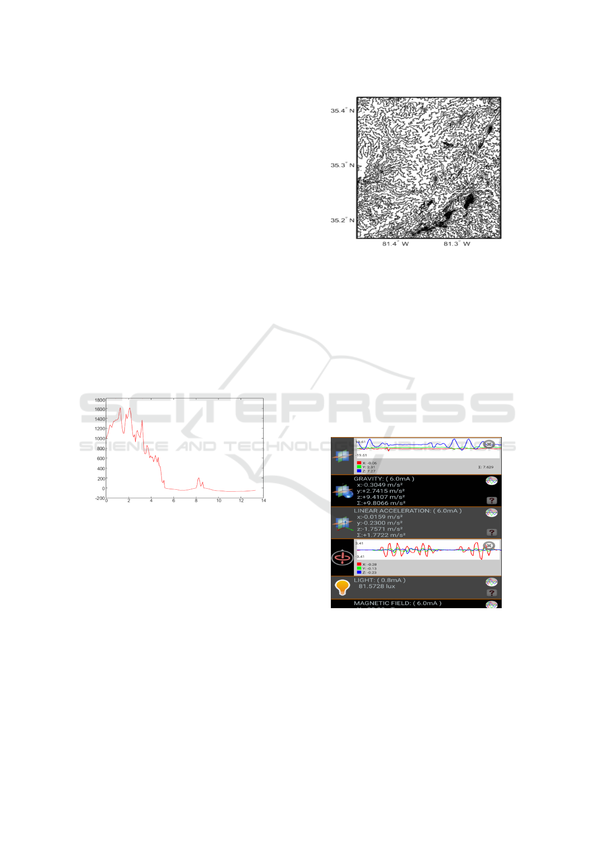
The elevation data with respect to the coordinate
data is extracted employing a digital elevation model
(DEM) (Figure 5). DEMs store the terrain informa-
tion as data using a Raster Data Model which repre-
sent the world as a surface divided into regular grid
of cells. Raster models are useful in storing data
which varies continuously. There are various DEM
data sources available free of cost all with compara-
tive degrees of resolution and accuracy.
Figure 5: Extracted Elevation profile on MATLAB.
MATLAB itself provides various DEM sources and
pre-existing functions to manipulate them (Figure 6).
Google Earth/Maps also provides elevation data and
there are various online resources which can be used
to extract the relevant geo-referenced elevation data.
In our work, we used all these methods to collect the
relevant elevation and coordinate data.
5.2 Preprocessing of Sensor Data
In order to reduce errors and computation time, the
derived sensor data is preprocessed. For acceleration
data, the effect of gravity is subtracted and a smooth-
ing filter such as averaging filter and a FFT based
smoothing filter is applied to reduce the effects of
noise. A bandpass filter with appropriate cut-off fre-
quencies will provide a better result.
Figure 6: Extracted topographic map from a DEM source
in MATLAB.
As noted, most of the drift error in position data
is due to the gyroscope readings. The gyroscope data
can be fused with that of magneto scope. Also, the
smartphone can be kept still on a solid surface after
moving it for a while. This will allow us to calculate
and thereafter subtract a definite bias from our accel-
eration and angular velocity data. For barometer, the
readings should be appropriately modified with re-
spect to temperature, humidity and gravitational er-
rors.
5.3 Sensor Data Acquisition
Figure 7: Acquired Smartphone Sensor Data.
The Android sensor framework (Android.Com,
2009) is used to acquire raw sensor data and to mon-
itor for changes in the value of the sensor (Figure 7).
A sensor event provides you with four pieces of in-
formation: the name of the sensor that triggered the
event, the timestamp for the event, the accuracy of the
event, and the raw sensor data that triggered the event.
Two call back methods exist on SensorEventListener
WINSYS 2017 - 14th International Conference on Wireless Networks and Mobile Systems
98

interface: when the accuracy of sensor changes and
when sensor reports a new value.
5.4 Probable Path Patterns
In the case, no direct path trails exist between the
start position and the destination, probable path pat-
terns are calculated from the positional elevation data.
Imagining the map is divided into N number of cells,
with each cell consisting its positional and elevation
data, we will apply the 8-adjacency concept in the
neighbourhood of the cell.
The basic idea is to find an adjacent cell in the
heading of the destination whose elevation is less than
a predetermined value k (probably 2 metres). Path
finding algorithms, greedy algorithm, etc. can be used
for this. In our case, we leaned towards the use of Ant
Colony Algorithm for finding the probable paths.
1. S is a set of all data points/cells consisting the lo-
cational and altitude data
2. ω is a set of constraints: (1) cell chosen should lie
in the present 8-adjacency neighbourhood of the
present cell (2) the difference between the eleva-
tions is less than k metres (3) the next cell chosen
should lie between −95
◦
and 95
◦
.
3. Objective function, f : Minimize(N), where N ⊂S
and is the number of cells used for path to desti-
nation.
Depending on the value of N, a ranking system is
provided to the probable path with the highest rank-
ing given to the path having the lowest value. In the
unusual circumstance of the subject not following any
of the probable paths, the elevation profile can be used
to find paths with similar profile in the map.
5.5 Step and Heading Detection
In order to count the number of steps taken, we need
to first calculate the (dynamic) stride length as well
detect. Due to the highly erroneous nature of data
received otherwise, the relationship between z-axis
acceleration data and the stride length is exploited.
Kalman filter is used with one of the equations
l
h
=
4
√
a
max
−a
min
or
l
h
=
3
r
1
N
∑
N
i=1
|a
i
| or
l
h
=
1
N
∑
N
i=1
|a
i
|−a
min
a
max
−a
min
for a better grasp on the dynamic nature of stride
length. For heading estimation, the angular displace-
ment data is obtained from the accelerometer, gyro-
scope and magnetometer readings.
5.6 Step Sequence Detection
After creating of several probable paths, step se-
quence arrays consisting of the azimuthal angle differ-
ence between each step is created. The same is done
for the actual subject movement. Taking a k width
window from this array, the values are correlated with
the values of the probable paths in order to identify
the probable path being used by the subject.
5.7 Pattern Correlation
The elevation profile of the path that the subject is tak-
ing is created along with the motion. This elevation
profile is then correlated (pattern or map correlation)
with the precomputed elevation profile. The correla-
tion is done on a frequent basis, taking parts of the
elevation profile as well as the whole. Pattern corre-
lations can be computed directly (uncentered) or by
computing anomalies from a central mean (centred).
This correlation process allows us to reduce the po-
sitional ambiguity and bypass the necessity to over-
come noise by providing us landmarks for position
identification.
5.8 Algorithm
Finally, the overall algorithm (Flow chart in Figure 8)
is as follows:
1. The initial point data is collected from GPS and
cellular connection, etc. Coordinates and eleva-
tion data for the present position is collected.
2. DEM data server is accessed and a DEM tile of
adequate map area is downloaded. Tuples of Map
data (latitude, longitude, altitude) are created. Ad-
ditional information such as weather forecast, etc.
(for barometer reading correction) is also col-
lected and sampled at this juncture.
3. Acquisition and pre-processing of sensor data to
reduce errors in the reading.
4. Calculation of step length using z-axis accelerom-
eter data and Extended Kalman Filter. Step Detec-
tion and Heading Detection using the sensor data.
5. Creation of probable path patterns (with ranking)
via the Probable Path Algorithm. Data sets of (lat-
itude, longitude, altitude) for each of these pat-
terns are created.
6. Step heading sequence and altitude pattern is also
created for each of these paths.
7. Create positional approximates by dead reckoning
using step counts, step length and heading infor-
mation. Cross reference these positions to saved
DEM data and create tuples of Calculated Data
An Offline Outdoor Navigation System with Full Privacy
99
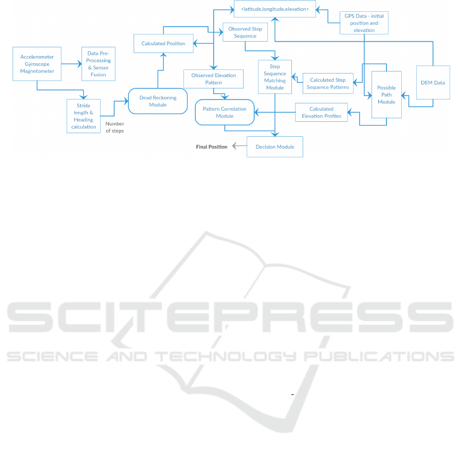
Figure 8: The flow chart of the proposed Personalised Navigation System.
(latitude, longitude, altitude). Create the altitude
pattern and step sequence array.
8. A window of adequate length is moved back and
forth and is used to correlate the measured step
sequence with that of the probable paths (going
down the ranking).
9. The measured elevation profile is correlated with
that of the expected paths. Given appropriate error
allowance δ, the elevation patterns are correlated
piecewise as well on an overall basis and the po-
sition corrected periodically.
10. In case a centre server is set up helping in sharing
the users’ data(the users choose to send the data
voluntarily). The data can be collected anony-
mously, without any reference to the identity of
the user who had used the path, etc. Probable path
patters and their position and elevation data will
be averaged out and the ranking of the particular
path will be decided by the number of users using
that path. This will greatly increase the overall
accuracy of the system.
6 CONCLUSION AND FUTURE
WORK
In this short paper, we have presented an offline nav-
igation system and some possible applications. Our
proposed algorithm creates a framework in which fur-
ther study can be done to achieve the creation of
a highly accurate offline positioning system. We
build our case centering on technologies available at
present. The paper argues that despite the obvious
failings of current MEMS and positioning technol-
ogy, we can use better algorithms to counter these
failings to achieve our objectives. We identify the ba-
sic building blocks and error sources of the existing
algorithms, which allows us to create a clear path-
way for further study. Privacy is a strong point of
our proposal and many secrecy/privacy-aware appli-
cations in the intelligence and military fields can be
developed. Moreover, our technique may have im-
plications in a large set of possible domains like ad-
venture sports, civil protection, location-base gaming,
speleology, and so on.
REFERENCES
Alzantot, M. and Youssef, M. (2012). Uptime: Ubiquitous
pedestrian tracking using mobile phones. In WCNC,
pages 3204–3209. IEEE.
Android.Com (2009). Sensors overview.
Android Developers’ API Guides.
https://developer.android.com/guide/topics/sensors/
sensors overview.html.
Constandache, I., Choudhury, R. R., and Rhee, I. (2010).
Towards mobile phone localization without war-
driving. In Infocom, pages 1–9. IEEE.
Elmenreich, W. (2002). An introduction to sensor fusion.
Vienna University of Technology, Austria.
Feliz Alonso, R. ’u. l., Zalama Casanova, E., and G mez
Garc
´
ı a Bermejo, J. (2009). Pedestrian tracking using
inertial sensors. Journal of Physical Agents, 3:35–42.
Ho, N.-H., Truong, P. H., and Jeong, G.-M. (2016).
Step-detection and adaptive step-length estimation for
pedestrian dead-reckoning at various walking speeds
using a smartphone. Sensors, 16(9):1423.
Iqbal, M. U. and Lim, S. (2010). Privacy implications of
automated gps tracking and profiling. Technology and
Society Magazine, 29(2):39–46.
Kim, J. W., Jang, H. J., Hwang, D.-H., and Park, C.
(2004). A step, stride and heading determination
for the pedestrian navigation system. Positioning,
1(08):0.
Link, J.
´
A. B., Smith, P., Viol, N., and Wehrle, K. (2013).
Accurate map-based indoor navigation on the mobile.
Journal of Location Based Services, 7(1):23–43.
WINSYS 2017 - 14th International Conference on Wireless Networks and Mobile Systems
100

Woodman, O. J. (2007). An introduction to inertial nav-
igation. Technical report, University of Cambridge,
Computer Laboratory.
Yun, X., Bachmann, E. R., Moore, H., and Calusdian, J.
(2007). Self-contained position tracking of human
movement using small inertial/magnetic sensor mod-
ules. In ICRA, pages 2526–2533. IEEE.
Zhou, R. (2016). Pedestrian dead reckoning on smartphones
with varying walking speed. In ICC, pages 1–6. IEEE.
An Offline Outdoor Navigation System with Full Privacy
101
