
A Novel Strategy for Adjusting Current Pulse Amplitude of FES-Systems
with PID based on PSO Algorithm Method to Control the Muscle Force
Abdennacer Ben Hmed
1,2
, Toufik Bakir
1
, Yoann Garnier
3
, Stephane Binczak
1
and Anis Sakly
2
1
Laboratory Le2i UMR 6306, CNRS, Arts et Metiers, Univ. Bourgogne Franche-Comte, Dijon, France
2
Research Unit ESIER in the National School of Engineers of Monastir, University of Monastir, Monastir, Tunisia
3
Laboratory INSERM UMR 1093, CAPS, Univ. Bourgogne Franche-Comte, Dijon, France
Keywords:
Functional Electrical Stimulation(FES), Muscle Force Model, PID Controller, PSO Algorithm, Pulse Ampli-
tude.
Abstract:
Adjusting stimulation parameters using control strategy based on mathematical model, that successfully pre-
dict muscle force, may improve the efficiency of Functional Electrical Stimulation (FES) systems. It present
an interesting task in industrial FES systems applications. In the present study, we investigate the PID control
tuning based on the Particle Swarm Optimization (PSO) algorithm at the first time in neuro-muscular systems
for updating automatically the stimulation pulse amplitude to track a desired force profiles. In the beginning,
The PSO algorithm is used to identify unknown force model parameters. Next, according to the identified
model, optimal PID gains are found by the same intelligent algorithm. The preliminary obtained results
showed promise of using intelligent algorithm on tuning PID to perform control sessions of FES systems.
1 INTRODUCTION
Functional electrical stimulation (FES) is of a great
interest in the medical and sportive domains. Indeed,
using such a technique by applying electrical stimula-
tion could treat subjects with motor functions diseases
due to neurological disorders. FES is also used in
the sportive domain to improve sportive performances
levels and to define efficient exercises protocols. Un-
til now, this technique allows to treat some diseases
using specific protocols that induce the rapid appear-
ing of the muscle fatigue. In addition, the generated
movements of the treated muscles by these protocols
are imprecise (Bickel et al., 2011). This is due to
the use of a basic stimulation pattern with constant
parameters (frequency, amplitude and pulse width).
However, using control technique could delay the ap-
pearing of the muscle fatigue and give more precise
movements (Doll et al., 2015), (Yochum et al., 2012).
The control techniques will act on the stimulation pa-
rameters of the FES to reach the aforementioned per-
formances.
Determining the appropriate FES strategy for a
specific muscle is primordial to obtain a targeted re-
sponse by maximizing the skeletal muscle perfor-
mance(Doll et al., 2015). The efficiency of the chosen
strategy depends on the physiological conditions of
the subject muscle. To perform more efficient strate-
gies, mathematical models that are based on experi-
ments could be used to predict force response and to
design closed loop feedback controllers in FES sys-
tems. Many control strategies have been proposed in
order to track a desired behaviors such as the joint
torque and the muscle activation (Liu et al., 2005), (Li
et al., 2015), (Kurosawa et al., 2005), (Ferrarin et al.,
1996).
The generated force by skeletal muscle was mod-
eled by different ways (physiological activity, black
box modeling, etc.). One of the most popular models
that reflect as well as possible the muscle behavior
is a physiology-based model that was developed by
Ding et al (Ding et al., 2000), (Ding et al., 2003).
In (Law and Shields, 2006), The comparison of the
model of Ding et al with other models showed that
the Ding modelis the best one to predict the muscle be-
havior under different physiological conditions. It has
also showed that in the case of spinal cord injuries
(SCI) subjects, the Ding model is of good accuracy
when used to fit the paralyzed muscle forces (Ding
et al., 2007). Until the present, the control of the
force response actuated by the quadriceps muscles us-
ing model-based approaches has not yet well treated
(Ben Hmed et al., 2015), (Ben Hmed et al., 2016).
664
Hmed, A., Bakir, T., Garnier, Y., Binczak, S. and Sakly, A.
A Novel Strategy for Adjusting Current Pulse Amplitude of FES-Systems with PID based on PSO Algorithm Method to Control the Muscle Force.
DOI: 10.5220/0006473306640669
In Proceedings of the 14th International Conference on Informatics in Control, Automation and Robotics (ICINCO 2017) - Volume 1, pages 664-669
ISBN: 978-989-758-263-9
Copyright © 2017 by SCITEPRESS – Science and Technology Publications, Lda. All rights reserved

The main objective of this study is to control the
muscle force by adjusting the stimulation pulse am-
plitude of FES Stimulator using the PSO-based PID
controller. The PSO algorithm is firstly introduced to
identify the optimal parameters of the nonlinear force
model using experimental data. Then, we will dis-
cuss the Off-line PID controller design using the PSO
algorithm adopting to the identified model. This effi-
cient tuning of the PID control gains is then applied to
control the muscle force model. it’s performance and
effectiveness will be discussed by a set of simulation
results.
2 MUSCLE FORCE MODEL
The muscle force model developed by Ding et al
is comprised of two nonlinear differential equations
(Ding et al., 2000), the first one Eq. (1) represents
calcium kinetics and the calcium-troponin interaction
and the second equation Eq. (2) represents the devel-
oped force:
dC
N
dt
=
1
τ
c
n
∑
i=1
R
i
exp(−
t − t
i
τ
c
) −
C
N
τ
c
, (1)
dF
dt
= A
C
N
K
m
+C
N
−
F
τ
1
+ τ
2
C
N
K
m
+C
N
. (2)
The force output is monitored using six constant pa-
rameters (A, R
0
, τ
c
, τ
1
, τ
2
and K
m
). The definitions
of the used symbols in the above equations are de-
tailed in(Ding et al., 2000), (Ding et al., 2003). The
term R
i
in Eq. (1) is a scaling term that accounts for
the nonlinear summation of the Ca
2+
transient within
the muscle fibers in responses to two closely spaced
pulses:
R
i
=
1 f or i = 1,
1 + (R
0
− 1) exp(−
t
i
−t
i−1
τ
c
) f or i > 1.
(3)
Testing this force model under diversity of physiolog-
ical conditions (Ding et al., 2007) and with different
types stimulation train (type of train, frequency, pulse
width) shows a good agreement between measured
data and estimated model (Ding et al., 2000).
3 SYSTEM IDENTIFICATION
AND CONTROL BASED PSO
ALGORITHM
3.1 Particle Swarm Optimization
Algorithm(PSO)
PSO technique has been developed by Kennedy and
Eberhart in 1995. It is a population-based approach
for optimization problem. It is derived from the
swarm intelligence such as birds flocking. This
method has been chosen thanks to its effectiveness,
simplicity and reduced parameters number. The PSO
has been investigated in many applications such as
complication function, combinational optimization
and fuzzy system control (Precup et al., 2014).
At each algorithm iteration, the velocity of each
particle will be updated following this equations:
ν
t+1
i
= ων
t
i
+ c
1
r
1
(Pbest
t
i
− χ
t
i
) + c
2
r
2
(Gbest
t
− χ
t
i
),
(4)
where ν
i
and χ
t
i
are respectively the velocity and the
position of the particle i in the t
th
iteration. ω is the
inertia weight, c
1
and c
2
are acceleration coefficients,
r
1
and r
2
are two random numbers in the range [0,
1]. Pbest
t
i
is the best previous position of this parti-
cle (memorized by every particle). Finally, Gbest
t
is
the best previous position among all the particles in
the t
th
iteration (memorized in a common repository).
After calculating the velocity, the new position of ev-
ery particle can be calculated as follow:
χ
t+1
i
= χ
t
i
+ ν
t+1
i
. (5)
Finally, the PSO algorithm can be summarized by six
steps as shown by the algorithm.1 and its implemen-
tation considered in this study is developed with a
maximum generation value of 100 (Max iteration), a
swarm size =10, a inertia weight (ω = 0.9) and accel-
eration coefficients (c
1
= c
2
= 1.2)
Algorithm 1: Particle Swarm Optimization al-
gorithm
1. Initialization;
while t < Max iteration do
t ←− t + 1;
2. Evaluate each particle’s position
according to the objective function (Eq. (6)
or Eq. (10));
if χ
t
i
is better then Pbest
t
i
then
Update it;
3. Determine the best particle Gbest
t
i
(according to the particle’s Pbest
t
i
);
4. Update particle’s velocities using Eq.
(4);
5. Move particles to their new positions
using Eq. (5);
6. Find the Gbest particle according to the
global best objective function
3.2 Muscle Parameter Identification
In General, the process of system identification con-
sist to compare the system outputs with the parameter-
A Novel Strategy for Adjusting Current Pulse Amplitude of FES-Systems with PID based on PSO Algorithm Method to Control the Muscle
Force
665

ized model based on a performance function giving a
measure of how well the model response fits the sys-
tem output (Alfi and Modares, 2011), (Türk¸sen and
Tez, 2016). For simplicity, under nonfatigue condi-
tions, τ
c
was fixed at 20 ms. Additionally, Ding et al
showed in (Ding et al., 2003) that for all physiolog-
ical conditions parameter R
0
could be expressed as
a function of K
m
(R
0
= K
m
+ 1.04). Thus, only four
free parameters need to be identified for each subject
(A,τ
1
,τ
2
and K
m
). This four force model parameters
were identified from fitting the model to the force data
using the following objective function G:
G =
1
N
N
∑
k=1
(F
p
(k;A,τ
1
,τ
2
,K
m
) − F
m
(k))
2
, (6)
where F
p
is the predicted force by Eqs. (1) and (2) and
F
m
represents the experimental force data and N is the
number of the considered data points. G is minimized
using the PSO algorithm (Alfi and Modares, 2011),
which is employed to identify the optimum values for
the four variables numerically by mean of an objective
function.
3.3 PID Control based PSO
The PID controller is the most widely used controller
for industrial applications. In practice, controlled sys-
tems usually have some features such as nonlinear-
ity and time delay, which make PID parameter tuning
complex. In control tuning literature, Many PID tun-
ing methods (Jaen-Cuellar et al., 2013) such as the
Ziegler-Nichols (ZN) method and many other artifi-
cial intelligence techniques such as neural networks
(Qiu et al., 2014), fuzzy (Bouallègue et al., 2012)
and intelligent optimization algorithm such as Ge-
netic Algorithm (GA) (Jaen-Cuellar et al., 2013),(Qiu
et al., 2014) and PSO (Alfi and Modares, 2011) were
proposed to find the optimal parameters of a PID
controller. In this work, we investigate the intelli-
gent PSO algorithm because of it efficiency compar-
ing to others control-tuning methods (Nagaraj and Vi-
jayakumar, 2011).
The continuous form of PID controller can be de-
scribed as follows:
u(t) = K
p
e(t)+ K
i
Z
τ
0
e(τ)dτ + K
d
de(t)
dt
, (7)
where, e(t) is the error signal between the desired and
actual outputs, u(t) is the control input, K
p
, K
i
and
K
d
are the usual tuning gains. Using trapezoidal ap-
proximation for Eq. (5), the discrete-form of the PID
algorithm is generally given as:
u(k) = K
p
e(k) + K
i
k
∑
i=1
e(i) + K
d
(e(k) − e(k − 1)).
(8)
3.4 Controller Design: Control of the
Muscle Force
After achieving the Off-line tuning of the PID con-
troller based on the optimization algorithm (PSO) (see
Table.1), we explore the obtained optimal gains to
track the desired reference defined by clinicians. The
calculated continuous control signal α(t) is used then
to compute the pulse amplitude.
α(t) = u
pid
, (9)
+
-
Force model
PID
controller
PSO
algorithm
K
p
K
i
K
d
F
F
ref e u
Figure 1: PID controller tuning based on the PSO algorithm
for muscular force control.
Fig. 1 illustrates the PID controller design using
intelligent algorithm (PSO), where F
re f
is the desired
output and F is the system output. In the control
process, the objective is to minimize the fitness func-
tion, defined as the Mean Square Errors (MSE), which
could be used to determine the performance of any
optimization algorithm.
MSE =
1
N
N
∑
k=1
(Fre f (k) − F(k))
2
. (10)
Table 1: Optimal gains tuning of the PSO based PID con-
troller.
K
p
K
i
K
d
0.0935 0.0012 0.1511
In the computer simulation of the controlled force
model, the adjusted stimulus output is calculated us-
ing the sum of pulses defined in Eq. (1) as muscle
model’s input where the train of pulses is multiplied
by the term α
i
correspondent to the amplitude of the
i
th
pulse applied to the muscle as shown in Fig. 2. The
modified expression is given as follows:
u
∗
n
(t) =
1
τ
c
n
∑
i=1
α
i
R
i
exp(−
t − t
i
τ
c
), (11)
where, at each pulse, the stimulus output’s amplitude
α
i
delivered by the stimulator toward quadriceps mus-
cle is computed using the discrete formula of the con-
sidered PID controller:
α
i
= α(t)∗ δ(t − iT ), with T = t
i
− t
i−1
, (12)
ICINCO 2017 - 14th International Conference on Informatics in Control, Automation and Robotics
666
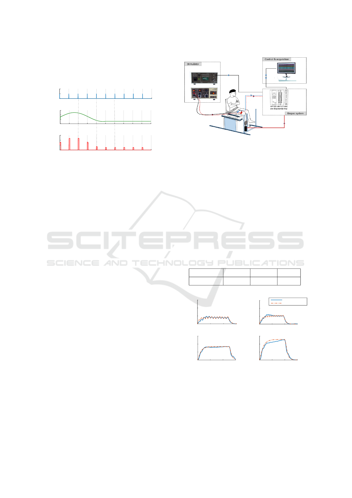
where T is the sampling period and δ is a Dirac func-
tion used to detect the amplitude given by the continu-
ous control signal, it consist to the TTL trigger signal
of the stimulator system in practice.
0 20 40 60 80 100 120 140 160 180 200
0 20 40 60 80 100 120 140 160 180 200
Time (ms)
0 20 40 60 80 100 120 140 160 180 200
Continuous control signal α (t)
Dirac function δ(t)
Stimulus output u
*
n
(t)
Figure 2: Schematic representation illustrate the proposed
method to compute the pulse amplitude on the control of
the muscle force by FES systems.
4 RESULTS AND DISCUSSION
4.1 Experimental Setup
As a pilot study, the system tests were conducted on
one subject up on his consent (a volunteer sports-
man). To test and identify the muscle force model,
stimulation pulses were standardized to a fixed am-
plitude and pulse width. For the test subject the pulse
amplitude was fixed to 50 mA and the pulse width
was maintained at 500 µs. The quadriceps muscle is
stimulated by a pair of surface electrodes connected
to the DS7AH Digitimer stimulator (Digitimer Ltd,
Welwyn Garden City, Hertfordshire. AL7 3BE. Eng-
land). Under stimulation session, subject was seated
with trunk-thigh angle at 90 and mechanical measure-
ments were recorded using an isometric ergometer
that comprised a machine typically used for strength
training (Multi-form, la Roque d’AnthÃl’ron, France)
connected one strain gauge (STC 250 kg, sensitivity:
2.9997 mV/V, Celtron Technologies Inc., Santa Clara,
CA, USA). During the experimentation, data were
digitized and stored for analyses (Biopac MP150 A/D
converter and AcqKnowledge v4.2 software, Biopac
Systems Inc., Santa Barbara, CA) as shown in Fig. 3.
4.2 Testing and Identification of the
Force Model
In order to identify subject-specific parameters, all of
the force model parameters (A, τ
1
, τ
2
, K
m
and R
0
)
were set as free within reasonable bounds. Further-
more, it should be noted that the identified parame-
Figure 3: Schematic representation of experimental ar-
rangement for data collection.
ters for this model are depending of the standardized
pulse’s magnitude, the muscle properties of the test
subject, size and placement of the stimulation pads.
In this study, the identified muscle parameters for
the considered subject were calculated using data col-
lected from a simple protocol (pair of 12.5Hz-33Hz )
where muscle is stimulated by a pulse train sequence
of a CFT80 during 1s and relaxed from 500ms, fol-
lowed by a CTF30 during 1s and then relaxed for
500ms. This protocol was chosen to be the most ef-
fective train for force model parameter identification.
The identified muscle parameters values are provided
in Table 2, which cites the mean best parameters val-
ues calculated over 10 runs.
Table 2: Identified parameters force model.
A τ
1
τ
2
K
m
1.755N/ms 68.32ms 102.2ms 0.5631
Time (ms)
0 500 1000 1500
Force (N)
0
50
100
150
Time (ms)
0 500 1000 1500
Force (N)
0
50
100
150
Time (ms)
0 500 1000 1500
Force (N)
0
50
100
150
Time (ms)
0 500 1000 1500
Force (N)
0
50
100
150
Experimental force
Predicted force
33 Hz
10 Hz
12.5 Hz
20 Hz
Figure 4: Examples of predicted force to different frequen-
cies stimulation Train (10Hz (CFT100), 12.5Hz (CFT80),
20Hz (CFT50) and 33Hz (CFT30)) when the model is pa-
rameterized by the CFT80-CFT30 protocol data for a typi-
cal subject.
To validate the identified model, a comparison be-
tween experimental and simulation results is shown
in Fig. 4. The performance of this model prediction
A Novel Strategy for Adjusting Current Pulse Amplitude of FES-Systems with PID based on PSO Algorithm Method to Control the Muscle
Force
667
Time (ms)
0 500 1000 1500
Control( α (t) )
0
2
4
Control
Time (ms)
0 500 1000 1500
Stimulus output( u
*
(t) )
0
0.2
0.4
0.6
Stimulus output
Time (ms)
0 500 1000 1500
Force (N)
0
50
100
150
200
Predicted force
Refrence (F
r
=80 N)
Time (ms)
0 500 1000 1500
Control( α (t) )
0
2
4
Control
Time (ms)
0 500 1000 1500
Force (N)
0
50
100
150
200
Predicted force
Refrence (F
r
=120 N)
Time (ms)
0 500 1000 1500
Stimulus output( u
*
(t) )
0
0.2
0.4
0.6
Stimulus output
Time (ms)
0 500 1000 1500
Force (N)
0
50
100
150
200
Predicted force
Refrence (F
r
=150 N)
Time (ms)
0 500 1000 1500
Stimulus output( u
*
(t) )
0
0.2
0.4
0.6
Stimulus output
Time (ms)
0 500 1000 1500
Control( α (t) )
0
2
4
Control
BA
C
(A-1)
(A-2)
(A-3)
(B-1)
(B-2)
(B-3)
(C-1)
(C-2)
(C-3)
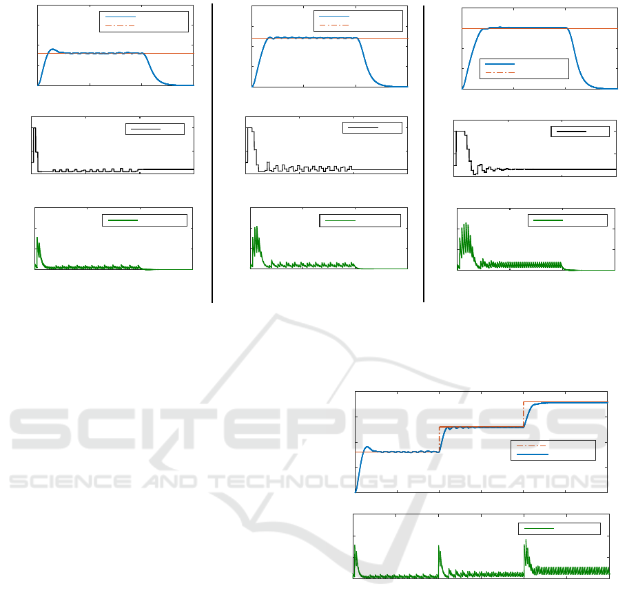
Figure 5: The performance of the PID based PSO control of the muscle force during 1s stimulation session for three desired
forces (A: F
re f
=80N, B: F
re f
=120N, C: F
re f
=150N) using the modified pulse train MCFT30. (A,B,C)-1 illustrate the de-
veloped force to track the desired force, (A,B,C)-2 illustrate the computed pulse amplitude α(t) and (A,B,C)-3 illustrate the
corresponding stimulus output applied to the quadriceps muscle.
was quantitatively assessed by computing the MSE
error between the predicted force and the measured
one. Fig. 4 proved the ability of the estimated model
to predict force response to a wide range of frequen-
cies trains (10Hz, 12.5Hz, 20Hz and 33Hz). In addi-
tion, the correspondence with the values identified by
Ding et al for the force model justifies the efficiency
of using PSO algorithm for nonlinear systems identi-
fication.
4.3 Control of the Muscle Force
The PSO-based PID control method is tested for var-
ious references forces (80, 120, 150N) with a Con-
stant Frequency Train (CFT20). The Fig. 5 (A), (B)
and (C) show respectively the ability of the devel-
oped force to track the desired references in (A,B,C)-
1 and the computed pulse amplitude in (A, B, C)-2
and finally in (A, B, C)-3, which illustrate the corre-
sponding stimulus output applied to muscle. In addi-
tion, in order to confirm the robustness of our devel-
oped strategy to control the muscle force, we present
in Fig. 6 the tracking of a set of three point refer-
ences by increasing the desired force with 50N ev-
ery 1s. All of the simulations results show that com-
bining both usual control strategy and intelligent op-
timization method can provide an efficient incorpo-
rated model into the feedback control system during
FES applications.
This preliminary results prove that our purpose of
Time (ms)
0 500 1000 1500 2000 2500 3000
Force (N)
0
50
100
150
200
Refrence
Predicted force
Time (ms)
0 500 1000 1500 2000 2500 3000
Stimulus output
0
0.2
0.4
0.6
Stimulus output
(a)
(b)
Figure 6: An example of the PID based PSO performance
on the control of the muscle force during 3s of stimulation:
(a) illustrates the tracking performance with respect to the
three set point references (80N, 130N, 180N) by increas-
ing the desired force with 50N every 1s. (b) illustrates the
corresponding computed stimulus pulse with the controlled
amplitude (the control signal).
controlling muscle force could be approved by the
new proposed stimulator DS8R from Digitimer (Dig-
itimer Ltd, Welwyn Garden City, Hertfordshire. AL7
3BE. England).
The new DS8R stimulator monitors the new ana-
logue voltage control applied at this input and adjusts
the stimulus current proportionally with this voltage
as each trigger input is detected.
ICINCO 2017 - 14th International Conference on Informatics in Control, Automation and Robotics
668

5 CONCLUSION
In this paper, a new controlling strategy PID based
on PSO algorithm was designed in order to control
the muscle force during stimulation sessions. this de-
veloped method is used to compute automatically the
stimulus pulse amplitude for each pulse applied to the
muscle. Also, using experimental data, the PSO algo-
rithm was explored to identify and provide an excel-
lent mathematical model that can simulate perfectly
the muscle response and as a result improved the con-
trol system. With regard to our current results, we
can conclude that designed control method based on
optimization approach can enhance performances of
control FES systems.
REFERENCES
Alfi, A. and Modares, H. (2011). System identification and
control using adaptive particle swarm optimization.
Applied Mathematical Modelling, 35(3):1210–1221.
Ben Hmed, A., Bakir, T., Binczak, S., and Sakly, A.
(2016). Model free control for muscular force by func-
tional electrical stimulation using pulse width modu-
lation. In Control Engineering & Information Tech-
nology(CEIT), 2016 4th International Conference on.
IEEE.
Ben Hmed, A., Bakir, T., Sakly, A., and Binczak, S. (2015).
Controlling muscular force by functional electrical
stimulation using intelligent pid. In Sciences and
Techniques of Automatic Control and Computer En-
gineering (STA), 2015 16th International Conference
on, pages 75–79. IEEE.
Bickel, C. S., Gregory, C. M., and Dean, J. C. (2011). Mo-
tor unit recruitment during neuromuscular electrical
stimulation: a critical appraisal. European journal of
applied physiology, 111(10):2399.
Bouallègue, S., Haggège, J., Ayadi, M., and Benrejeb, M.
(2012). Pid-type fuzzy logic controller tuning based
on particle swarm optimization. Engineering Appli-
cations of Artificial Intelligence, 25(3):484–493.
Ding, J., Chou, L.-W., Kesar, T. M., Lee, S. C., John-
ston, T. E., Wexler, A. S., and Binder-Macleod,
S. A. (2007). Mathematical model that predicts the
force–intensity and force–frequency relationships af-
ter spinal cord injuries. Muscle & nerve, 36(2):214–
222.
Ding, J., Wexler, A. S., and Binder-Macleod, S. A. (2000).
Development of a mathematical model that predicts
optimal muscle activation patterns by using brief
trains. Journal of applied Physiology, 88(3):917–925.
Ding, J., Wexler, A. S., and Binder-Macleod, S. A. (2003).
Mathematical models for fatigue minimization dur-
ing functional electrical stimulation. Journal of Elec-
tromyography and Kinesiology, 13(6):575–588.
Doll, B. D., Kirsch, N. A., and Sharma, N. (2015). Op-
timization of a stimulation train based on a pre-
dictive model of muscle force and fatigue. IFAC-
PapersOnLine, 48(20):338–342.
Ferrarin, M., D’acquisto, E., Mingrino, A., and Pedotti,
A. (1996). An experimental pid controller for knee
movement restoration with closed loop fes system. In
Engineering in Medicine and Biology Society, 1996.
Bridging Disciplines for Biomedicine. Proceedings of
the 18th Annual International Conference of the IEEE,
volume 1, pages 453–454. IEEE.
Jaen-Cuellar, A. Y., de J. Romero-Troncoso, R., Morales-
Velazquez, L., and Osornio-Rios, R. A. (2013). Pid-
controller tuning optimization with genetic algorithms
in servo systems. International Journal of Advanced
Robotic Systems, 10(9):324.
Kurosawa, K., Futami, R., Watanabe, T., and Hoshimiya, N.
(2005). Joint angle control by fes using a feedback er-
ror learning controller. IEEE Transactions on Neural
Systems and Rehabilitation Engineering, 13(3):359–
371.
Law, L. A. F. and Shields, R. K. (2006). Predicting human
chronically paralyzed muscle force: a comparison of
three mathematical models. Journal of applied physi-
ology, 100(3):1027–1036.
Li, Z., Hayashibe, M., Andreu, D., and Guiraud, D. (2015).
Real-time closed-loop fes control of muscle activation
with evoked emg feedback. In Neural Engineering
(NER), 2015 7th International IEEE/EMBS Confer-
ence on, pages 623–626. IEEE.
Liu, C.-L., Yu, C.-h., Chen, S.-C., and Chen, C.-H. (2005).
Evaluation of closed-loop control system for restoring
standing and sitting functions by functional electrical
stimulation. Biomedical Engineering: Applications,
Basis and Communications, 17(01):19–26.
Nagaraj, B. and Vijayakumar, P. (2011). A comparative
study of pid controller tuning using ga, ep, pso and
aco. Journal of Automation Mobile Robotics and In-
telligent Systems, 5:42–48.
Precup, R.-E., David, R.-C., Petriu, E. M., Preitl, S., and
R
˘
adac, M.-B. (2014). Novel adaptive charged sys-
tem search algorithm for optimal tuning of fuzzy
controllers. Expert Systems with Applications,
41(4):1168–1175.
Qiu, S., He, F., Tang, J., Xu, J., Zhang, L., Zhao, X., Qi, H.,
Zhou, P., Cheng, X., Wan, B., et al. (2014). Intelli-
gent algorithm tuning pid method of function electri-
cal stimulation using knee joint angle. In Engineering
in Medicine and Biology Society (EMBC), 2014 36th
Annual International Conference of the IEEE, pages
2561–2564. IEEE.
Türk¸sen, Ö. and Tez, M. (2016). An application of nelder-
mead heuristic-based hybrid algorithms: Estimation
of compartment model parameters. International
Journal of Artificial Intelligence, 14(1):112–129.
Yochum, M., Bakir, T., Lepers, R., and Binczak, S. (2012).
Estimation of muscular fatigue under electromyostim-
ulation using cwt. IEEE Transactions on Biomedical
Engineering, 59(12):3372–3378.
A Novel Strategy for Adjusting Current Pulse Amplitude of FES-Systems with PID based on PSO Algorithm Method to Control the Muscle
Force
669
