
Multi-disciplinary Optimization with Standard Co-simulation
Interfaces
Marco Inzillo
1
and Carlos Kavka
2
1
DIMES, Università della Callabria, via Pietro Bucci, Arcavacata di Rende, 87030, Cosenza, Italy
2
Department of Research and Development, ESTECO SpA, Area Science Park, Padriciano 99, 34149, Trieste, Italy
Keywords: Functional Mock-up Interface, Numerical Simulations, Multi-objective Optimization, Multi-disciplinary
Optimization, Co-simulation.
Abstract: Numerical simulations and optimization are at the base of the design process of modern complex engineering
systems. Typically, individual components are simulated by using highly specialized software tools applicable
to single or narrow domains (mechanical stress, fluid dynamics, thermodynamics, acoustic, etc.) and then
combined together in order to build complex systems to be co-simulated and optimized. This distributed
engineering development process requires that model components must be developed in such a way, that they
could be easily interchanged between different departments of the same company, may be geographically
distributed or even between independent companies. This position paper provides a short discussion about the
currently available standards and presents work in progress concerning the definition of new standards for the
interconnection of complex engineering systems and its optimization as required in modern engineering
design. The paper is complemented with a few examples which provides a base for further discussion.
1 INTRODUCTION
Modern engineering extensively relies on numerical
simulations, which can be used in the design phase of
almost any product. This process is typically handled
by highly specialized software applications, each of
which focuses in a single or a narrow set of
disciplines. With so large number of tools, a support
for the exchange of simulation models between
suppliers is required. The best possible answer to
integration and interoperability problems is the
adoption of a common standard. In particular, the
Functional Mock-up Interface (FMI) is emerging as
the leading industry standard to support model
exchange and co-simulation (Blochwitz, 2011). Its
main feature is the encapsulation of the different
model executors in predefined shells (Functional
Mock-up Units or FMUs) which provide all required
operations and data structures supporting interaction
and orchestration services. The standard is well
defined, widely used, and many support software
tools are provided in order to create FMUs or to link
them into other applications, facilitating the design of
FMI compliant software applications (Modelica,
2010). The co-simulation aspects of the FMI standard
focus on the interaction among models by following
a master-slave architecture, where the FMUs are the
slaves and an ad-hoc algorithm implements the
master logic. The standard does not impose a specific
master algorithm, but a significant number of
algorithms and techniques which cover many
industrial scenarios are provided in the literature
(Bastian, 2011) (Van Acker, 2015). The lack of a
defined master algorithm in the FMI standard is an
advantage in one sense, since a specific algorithm
with the required trade-off between complexity and
accuracy can be used for a specific industrial design
process. However, carefully design is essential to
avoid non-deterministic or unexpected behaviours as
noted for example in (Schierz, 2015).
Nowadays, globalized market requires industrial
engineering design strategies to be extremely
competitive, with the consequence that numerical
simulation by itself is not enough to successfully
accomplish industrial requirements. It necessarily has
to be combined with optimization techniques, which
are used to guide the simulation process in order to
obtain the best possible designs. Current engineering
design problems require to handle simultaneously
multiple objectives at the same time and consider also
multiple disciplines. Since the design objectives can
in many cases be contradictory between themselves
Inzillo, M. and Kavka, C.
Multi-disciplinary Optimization with Standard Co-simulation Interfaces.
DOI: 10.5220/0006472704530458
In Proceedings of the 12th International Conference on Software Technologies (ICSOFT 2017), pages 453-458
ISBN: 978-989-758-262-2
Copyright © 2017 by SCITEPRESS – Science and Technology Publications, Lda. All rights reserved
453

(think on power and fuel consumption in engine
design for example), the optimization strategies are
required to be multi-objective in order to consider all
objectives at the same time. Instead of producing a
single design as the result of the optimization process,
the multi-objective optimization (MOO) methods
produce the so-called Pareto front, which corresponds
to the set of solutions which represents the best trade-
off between the different objectives (Deb, 2014). A
multi-disciplinary engineering design process
requires also the use of Multi-Disciplinary
Optimization (MDO) methods to exploit the
interactions between the disciplines during
optimization, instead of considering each discipline
independently of the others.
The paper is organized as follows. Next section
presents related work on the use of the FMI standard
in the context of co-simulation and optimization.
Section 3 discusses research issues complemented
with current efforts to standardize the model structure
and interconnection patterns for the definition of
multi-component systems, while section 4 presents
two optimization examples in a multiple FMI and co-
simulation system. The paper completes with
conclusions and discussions about future research
directions.
2 RELATED WORK
Recently, the Modelica Association project “System
Structure and Parameterization” (SSP) has started
efforts to define a standardized format for the
connection of a set of FMU models (Köhler, 2016).
This standard is expected to define not only the
structure of the system, but also the parameter
definition of the system as a whole and its associated
experimental setup. Interestingly, a few open and
commercial tools are presenting in their web pages an
indication of preliminary support for the SSP standard
even if its development is yet ongoing.
Many algorithms and techniques have been
proposed in literature to implement the co-simulation
master algorithms, considering many different
scenarios and other aspects, like for example the co-
simulation of FMUs with different time rates (Van
Acker, 2015) and systems that include feedback loops
(Broman, 2013). Typically, the algorithms are
presented in the literature in terms of pseudocode
listings or non-executable diagrams, which can
eventually be used to generate code (Aslan, 2015)
(Galtier, 2015) (Cremona 2016). An exception is
(Campagna, 2016), where the algorithms are
represented with BPMN 2.0, a standard business
process formalism (OMG, 2017) which includes both
a graphical diagram and an executable representation.
The use of FMI as an automatic deployment
model and its integration in the modeFRONTIER
multi-objective and multi-disciplinary optimization
environment was presented in (Batteh, 2015). In this
work, the authors demonstrate the advantages of
using the FMI standard for model exchange in the
robust design of a heat exchanger, in the optimization
of an electric vehicle range and a hydraulic crane.
3 RESEARCH ISSUES
There are many ongoing research activities which
address open issues like multi-model exchange
standards, master co-simulation algorithms definition
and their role when combined with multi-objective
and multi-disciplinary optimization.
Concerning model exchange, a large number of
software tools support import and export operations
in FMU format, making FMI the de-facto exchange
standard in industrial engineering design today. One
important limitation of the FMI standard is that it can
be used to incorporate only a single model into an
FMU file. The work of the SSP Modelica project (as
presented in the previous section) is definitely one of
the best news for the engineering design community,
since a new official standard defined on top of FMI
will certainly provide an adequate framework for
formally specifying multiple FMI collaboration.
However, there is yet no clear indication if the
standard will cover also the co-simulation master
definition or it will just stop at the parameter
exchange and model structure. An adequate co-
simulation master algorithm is essential to guarantee
stability and accuracy in the co-simulation process
(Schierz, 2015). This aspect is particularly important,
since FMI for co-simulation does not define a
standard graphical or textual representation of a co-
simulation scenario. In particular, it does not specify
a way to describe how the involved FMUs are
coupled. The specification only states that subsystem
composition may be performed in different ways and
typically results in some form of a component-
connection graph structure (Modelica, 2011).
However, the way in which the different sub-systems
are orchestrated by the master algorithm, combining
discrete and continuous-time dynamics is left to the
algorithm definition provided by the co-simulation
tool. As mentioned in previous section, the BPMN 2.0
standard, which includes a graphical representation
and a directly executable representation, provides an
interesting approach for master algorithms definition.
ICSOFT 2017 - 12th International Conference on Software Technologies
454
The main advantage of this approach is that it makes
easy to understand, maintain and enhance the master
algorithms, which are not just simply hardcoded but
are made available in a standard format (Campagna,
2016).
Other important research issue concerns
optimization, which plays a major role in current
engineering design where systems are simulated by
using numerical models. The FMI standard provides
a well-defined interface, which can be used by
optimization tools to interact with the numerical
models. However, if the system under design is
composed of a number of sub-components, a kind of
global instance of the whole system is required in
order to handle all co-simulation and orchestration
aspects. The optimization system can then interact
just with this global instance, setting not only
individual FMU parameters, but also system-wide
parameters covering global settings. By including
information from all subsystems into a single
configuration file, the complete system becomes a
kind of black-box accessible from the outside world
by just specifying the values of the parameters and the
operations requested, getting back the values of
metrics when simulation is completed. The
discussions currently going on in the Modelica SSP
project are a good step in this direction.
4 EXAMPLES
This section introduces two simple examples, a work
in progress expecting to contribute to discussions on
the use of FMI, co-simulation and optimization in
engineering design, supporting a required discussion
on procedures, the use of standards and industrial
requirements.
All examples have been prepared with
OpenModelica for model definitions (OpenModelica,
2017), FMI SDK and Modelon FMI library for FMI
interaction (Modelica 2017), and modeFRONTIER
as the optimization tool (Esteco, 2017).
Since the SSP standard is not yet defined, a
custom XML file definition has been used in these
preliminary examples to specify the interaction
between the optimizer and the simulated system. Of
course, when a standard defined by the SSP project
will be approved, the format defined by the standard
will be used in the forthcoming research activities.
The currently proposed XML file contains 5 sections.
The first indicates the individual models that define
the complete system with one entry for each FMU.
The second section defines the connection patterns
between the different FMUs. The third section
contains the global parameters of the whole system,
the fourth section the individual parameters for each
FMU and the last section the list of outputs (or
metrics) to be extracted at the end of the co-
simulation process. This file can be complemented
with a section on configuration parameters for the co-
simulation algorithm, indicating also the required co-
simulation approach (different time steps, feedback
support, etc.).
4.1 Single Discipline Multi-objective
Optimization
The first example consists in the multi-objective
optimization of a single system with no co-simulation
requirements. The system is a well-known electrical
full-wave rectifier, which generates a DC voltage
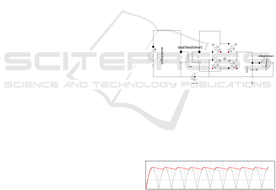
starting from standard AC voltage (see Figure 1). The
system contains four diodes to perform the wave
rectification process (identified with the label D), and
a capacitor (labelled as C) across the load resistance
in order to reduce the ripple of voltage variations.
Figure 1: The full wave rectifier. Note the four diodes
bridge (D), a capacitor (C), the AC generator on the left and
the DC voltage sensor on the right.
While this example is very modest in electronic
terms, it has been selected since it simple enough to
illustrate the concepts involved in this research. As
mentioned before, starting from an alternate voltage,
the objective is to produce a rectified continuous
voltage.
Figure 2: Voltage produced as result of the rectification
process.
Figure 2 shows the positive voltage cycles and on
top of them, the output produced by the system as the
result of the rectification process. Different values of
the saturation current of the diodes and the
capacitance of the capacitor generate different shapes
Multi-disciplinary Optimization with Standard Co-simulation Interfaces
455
of the curve. A good rectifier should provide a value
of the output voltage which is as steady and smooth
as possible, or in other words, the line on top of the
diagram should be as straight as possible.
In order to enhance the characteristics of the
rectifier, a multi-objective optimization is performed.
The optimization problem consists in finding the best
designs, by varying the values of the diodes saturation
current and capacitor capacitance, which generate a
voltage that is as near as the target voltage as possible,
with a minimum peak voltage. The XML file defining
the system contains one single line to identify the
FMU model, the definition of the two parameters of
the system (diodes saturation current and capacitor
capacitance) and two output metrics (DC voltage and
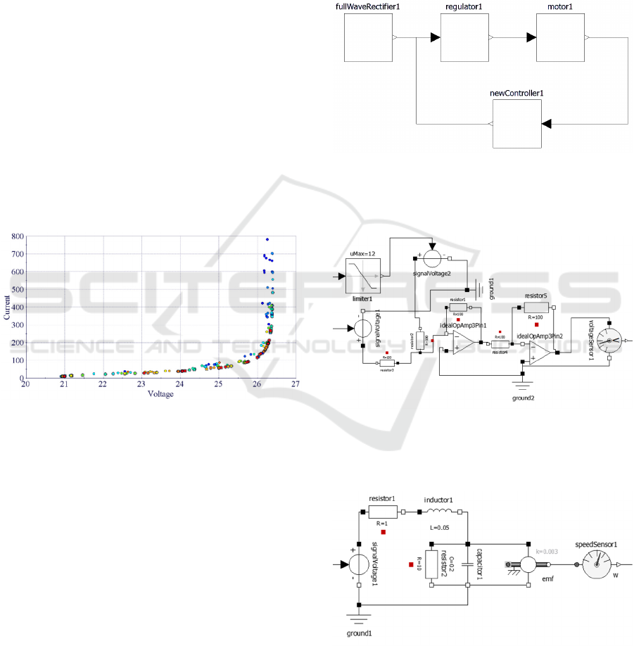
peak voltages). By using an optimization algorithm,
in our experiment a genetic algorithm, the
optimization process generates and evaluates a
number of designs, producing as result a Pareto front
(see Figure 3), where the designs that corresponds to
the best compromise between the required DC
voltage and the peak voltages are shown and can be
selected.
Figure 3: The Pareto front as a result of the optimization
process. The points in red (or double circled) corresponds
to the best solutions, which maximize the voltage and
minimize the peak current.
4.2 Multi-disciplinary Multi-objective
Optimization with Co-simulation
The second example consists in the multi-objective
optimization of a system composed of four sub-
systems with co-simulation requirements. Three
systems belong to the electronic domain while one
belongs to the mechanical domain. In this example,
each one of these four subsystems, is defined in terms
of a single FMU. The objective is to get an electric
motor running at a certain target speed, which is
reached in the minimum possible time, by selecting
adequate parameter for the controller and the full-
wave rectifier. The model is shown in Figure 4 as a
box diagram. The first subsystem (labelled as
fullWaveRectifier1) is the rectifier presented in
section 4.1, which generates DC from standard AC
for power requirements, the second subsystem
(regulator1) is a voltage regulator which generates the
voltage required in order to control the speed of a
motor (see Figure 5), the third subsystem (motor1)
simulates the DC motor (see Figure
6
), and the fourth
subsystem (newController1) is a typical PID
controller (see Figure 7 ), which controls the regulator
in order to keep the motor at the required speed.
Figure 4: The box diagram of the DC motor controller,
which consists of four subsystems, a full-wave rectifier, a
voltage regulator, a mechanical DC motor and a PID
controller.
Figure 5: The regulator, which produces the voltage
required to drive the DC motor based on the reference
voltage provided by the rectifier and the control signal sent
by the controller.
Figure 6: The DC motor, a mechanical system which rotates
at a speed defined by its input voltage and measured by a
speed sensor.
ICSOFT 2017 - 12th International Conference on Software Technologies
456
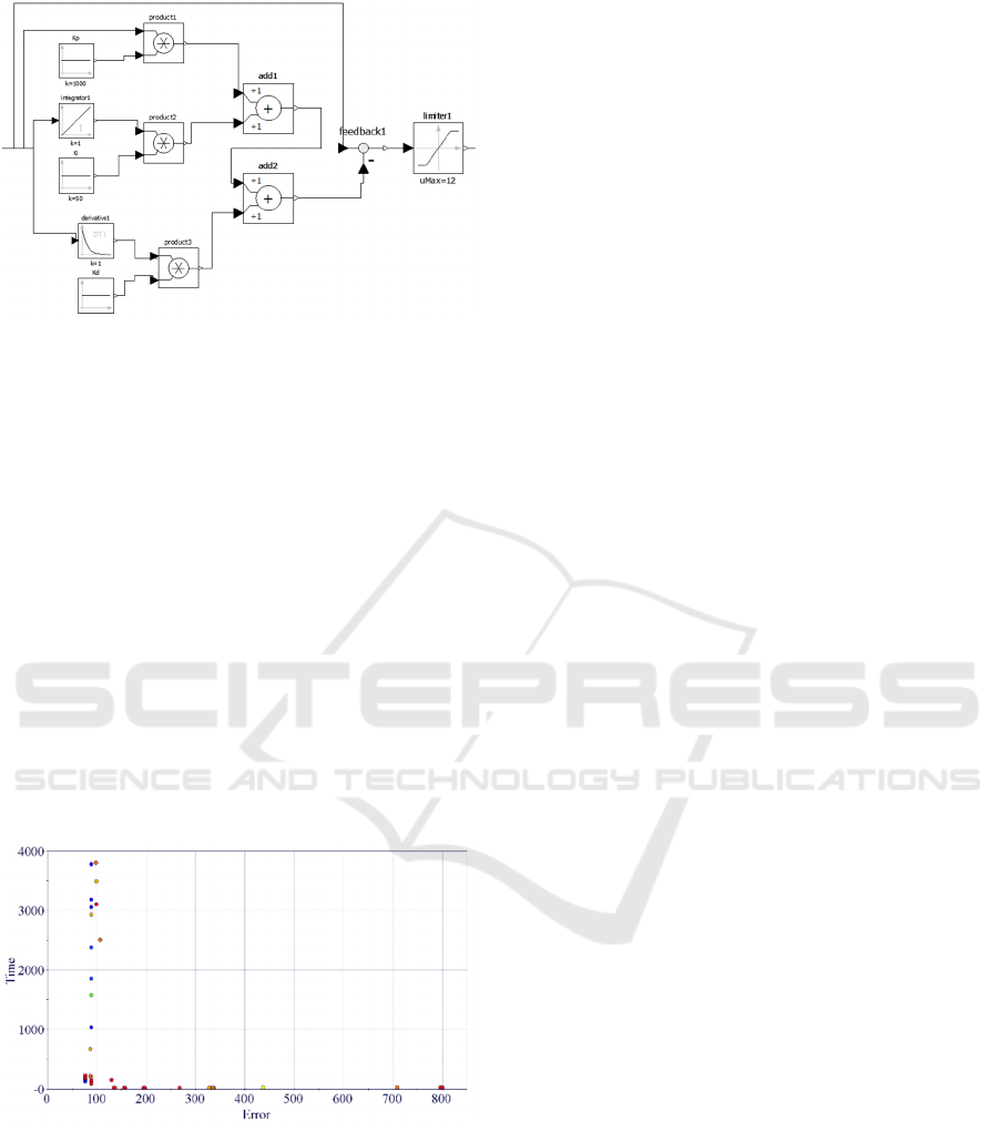
Figure 7: The PID controller, which has three coefficients
which are to be optimized in order to provide the right
control signals to the regulator.
Besides the two parameters for the DC rectifier
(described before), the controller introduces three
new parameters: the coefficients of the value of the
error (P), past values of the error (I) and the future
trends of the error (D), as usual in typical PID
controllers. Two objectives are considered for the
optimization: the error in the final velocity of the
motor, which has to be minimized, and the time
required for the motor to reach the required regime,
which also needs to be minimized.
The first section of the XML configuration file
used in this research experiments contains one line for
each FMU model. The connection section specifies
the connection pattern between the four models.
Beside rectifier parameters, the three PID coefficients
are specified in the parameters section.
Figure 8: The Pareto front as a result of the optimization
process. The points on the lower left corner corresponds to
the best solutions, which minimize the time required to
reach the expected regime while minimizing the error on
the speed.
Figure 8 shows the Pareto front obtained as results
of the multi-objective optimization process, with the
optimum designs which minimize both objectives
indicated in the lower left corner.
5 CONCLUSIONS
The FMI Functional Mock-Up Interface is a leading
technology which strongly encourages cooperation in
industrial engineering design. It provides a standard
interface for coupling physical models which can
eventually belong to different domains and may have
been developed with different simulation software
tools. FMI is particularly effective in addressing
problems like the export and the import of model
components in simulation tools for model exchange,
providing also a base for the standardization of co-
simulation interfaces in nonlinear dynamic systems.
However, even if some guidelines are presented in the
standard, no specifications for the co-simulation
master algorithm are formally defined.
The currently ongoing SSP project from Modelica
is definitely an effective attempt to defined a standard
approach to deal with multiple FMUs and their
parameters when complex systems with several
components have to be simulated and interchanged.
However, aspects like the master co-simulation
details are not yet fully considered.
This paper, as a position paper, raises some points
which are important to be considered in co-simulation
of complex systems, particularly in the context of
multi-objective and multi-disciplinary optimization.
REFERENCES
Aslan M., Oguztuzun H., Durak U., and Taylan K., 2015,
MOKA: An Object-Oriented Framework for FMI Co-
simulation, in Proceedings of the Conference on
Summer Computer Simulation, San Diego, CA, USA:
Society for Computer Simulation International, pp. 1–8
Bastian J., Clauß C., Wolf S., and Schneider P., 2011,
Master for co-simulation using FMI, in 8th
International Modelica Conference, Dresden.
Batteh J., Gohl J., Pitchaikani A., Duggan A., and Fateh N.,
2015, Automated Deployment of Modelica Models in
Excel via Functional Mockup Interface and Integration
with modeFRONTIER, in Proceedings of the 11th
International Modelica Conference, Versailles, France.
Blochwitz T., Otter M., Arnold M., Bausch C., Clau C.,
Elmqvist H., Junghanns A., Mauss J., Monteiro M.,
Neidhold T., Neumerkel D., Olsson H., Peetz J.-V., and
Wolf S., 2011, The Functional Mockup Interface for
Tool independent Exchange of Simulation Models, in
Proceedings of the 8th International Modelica
Conference.
Broman D., Brooks C., Greenberg L., Lee E. A., Masin M.,
Tripakis S. and Wetter M., 2013, Determinate Composi-
tion of FMUs for Co-simulation, in Proceedings of the
Eleventh ACM International Conference on Embedded
Multi-disciplinary Optimization with Standard Co-simulation Interfaces
457

Software, ser. EMSOFT ’13. Piscataway, NJ, USA:
IEEE Press, pp. 2:1–2:12.
Campagna D., Kavka, C., Turco A., Pogace B., Poloni C.,
2016, Solving time-dependent coupled systems through
FMI co-simulation and BPMN process orchestration,
Proceedings of the 2016 IEEE International
Symposium on Systems Engineering (ISSE),
Edinburgh, UK.
Cremona F., Lohstroh M., Tripakis S., Brooks C., and A.
Lee E., 2016, FIDE: An FMI integrated development
environment, in Proceedings of the 31 Annual ACM
Symposium on Applied Computing, SAC ’16. ACM,
pp. 1759–1766.
Deb, Kalyanmoy, 2014, Multi-objective optimization, in
Search methodologies: introductory tutorials in
optimization and decision support techniques, Editors:
Burke E, Kendall G, Springer, pp. 403-449
Esteco 2017, modeFRONTIER: the multi objective and
multi-disciplinary optimization environment,
http://www.esteco.com/modefrontier.
Galtier V., Vialle S., Dad C., Tavella J.-P., Lam-Yee-Mui,
and Plessis G, 2015, FMI-based distributed multi-
simulation with DACCOSIM, in Proceedings of the
Symposium on Theory of Modelling & Simulation:
DEVS Integrative M&S Symposium, Society for
Computer Simulation International, pp. 39–46.
Köhler J., Heinkel H.M., Mai P., Krasser J., Deppe M. and
Nagasawa M., 2016, Modelica-Association-Project
System Structure and Parameterization – Early Insights,
Proceedings of the 1st Japanese Modelica Conference,
May 23-24, 2016, Tokyo, Japan, pp. 35-42
Modelica Association Project, 2017, Functional Mock-up
Interface for Co-Simulation, https://www.fmi-standard.
org.
OMG, 2017, The Business Process Model and Notation
BPMN 2.0 standard, http://www.bpmn.org.
OpenModelica, 2017, OpenModelica: the open source
Modelica based modelling and simulation environment.
https://www.openmodelica.org.
Schierz T., Arnold M., and Claus C., 2015, Co-Simulation
with communication step size control in an FMI
compatible master algorithm, in Proceedings of the
11th International Modelica Conference, Versailles,
France.
Van Acker B., Denil J., Vangheluwe H., and De
Meulenaere P., 2015, Generation of an Optimised
Master Algorithm for FMI Co-simulation, in
Proceedings of the Symposium on Theory of Modelling
& Simulation: DEVS Integrative M&S Symposium,
ser. DEVS ’15. San Diego, CA, USA, pp. 205–212.
ICSOFT 2017 - 12th International Conference on Software Technologies
458
