
First-hop Redundancy Protocols in Omnet++
A New FHRPS Available in ANSAINET
Vladimír Veselý, Jan Holuša and Ondřej Ryšavý
Faculty of Information Technology, Brno University of Technology, Božetěchova 2, Brno, Czech Republic
Keywords: First-hop Redundancy Protocols, HSRP, GLBP, FHRP, ANSAINET, OMNeT++.
Abstract: The high-availability comprises a critical feature of any enterprise local area or data-center network. Because
of the importance of high-availability, network designers and administrators expect support from tools aiding
to deliver the correct configuration. Simulation is widely accepted approach for testing network design and
configuration helping to reveal possible issues in functionality and performance. OMNeT++ simulator
provides INET framework offering models of Internet devices, protocols and mechanisms. This paper
presents an extension of INET framework with two high-availability protocols, namely, HSRP and GLBP.
This extension enables to accurately simulate scenarios with default-gateway redundancy features, which was
not easily possible before. In the paper, we briefly overview the basic concepts of these protocols, describe
the design of simulation models and present verification and validation results.
1 INTRODUCTION
The default-gateway is a crucial device within any
local area network because it provides connectivity to
remote destinations. First-hop redundancy protocols
(FHRP) guarantees non-stop operation of default
gateway thus increasing high-availability of network
and its components. The design of complex mission-
critical networks benefits from the use of various
techniques in pre-deployment phase. Network
simulation can reveal several serious problems with
the network design, configuration of network devices
or possible performance bottlenecks. Network
infrastructure that is expected to provide continuous
services relies on the deployment of the high-
availability mechanism.
OMNeT++ simulator is shipped with the INET
library that aims at providing models for Internet
devices, protocols, and a mechanism to help with
network design and configuration testing and
evaluation. The Automated Network Simulation and
Analysis for Internet Environment (ANSAINET)
project is dedicated to the development of a variety of
simulation models compatible with RFC
specifications or referential implementations, which
extends the standard INET framework. The
ANSAINET now supports following FHRPs:
Cisco’s proprietary Hot Standby Router Protocol
(HSRP);
IETF’s standard Virtual Router Redundancy
Protocol (VRRP);
Cisco’s proprietary Gateway Load Balancing
Protocol (GLBP).
In this paper, we focus on HSRP and GLBP because
we already covered functionality and implementation
of VRRP in our previous paper article (Veselý and
Ryšavý, 2015).
This paper has the following structure. Section 2
covers a quick overview of existing FHRP
implementations. Section 3 describes the operational
theory and implementation design notes. Section 4
contains validation scenarios. The paper is concluded
in Section 5, which also outlines our future work.
2 STATE OF THE ART
This section briefly overviews existing FHRP
implementations for hardware/software routers and
also simulators.
VRRP protocol is being supported by a majority
of router manufacturers, e.g. (Hewlett Packard
Enterprise, 2012), (MikroTik, 2015), (Brocade
Communications Systems, 2015). Moreover, open-
source software implementations exist for Unix-
based environments (Cassen, 2016), (Bourgeois,
2017), (Arnaud, 2017). Even thou HSRP is marked as
Veselý, V., Holuša, J. and Ryšavý, O.
First-hop Redundancy Protocols in Omnet++.
DOI: 10.5220/0006441503310339
In Proceedings of the 7th International Conference on Simulation and Modeling Methodologies, Technologies and Applications (SIMULTECH 2017), pages 331-339
ISBN: 978-989-758-265-3
Copyright © 2017 by SCITEPRESS – Science and Technology Publications, Lda. All rights reserved
331
proprietary, Cisco does not force any licensing of it
thanks to the unresolved clash of Cisco and IETF in
this matter (IETF, 2003). Hence, other vendors also
support HSRP in their devices (Juniper Networks,
2013). This situation differs for GLBP, which is only
available for Cisco devices as the assertion of Cisco’s
intellectual property rights explicitly forbids other
implementations.
Scarce FHRP availability exists for simulators
too. Cisco Packet Tracer (Cisco Systems, 2017)
allows HSRP configuration since version 5.3.3.
However, Cisco Packet Tracer is closed and
proprietary simulator used mainly as an education
tool. Some of Riverbed (formerly OPNET) products
(namely Modeler and IT Guru Specialist) offer a
lightweight simulation of HSRP and VRRP.
However, we find these implementations very limited
(e.g., improper message structure, inaccurate finite
state machines) in their functionality. We have been
not able to reproduce programmability or simulation
results of other researchers (Kaur and Bajaj, 2013),
(King and Sanchez, 2013) with the current Riverbed
products (because source codes are no longer
compatible). We are not aware of any FHRP support
by NS2/3.
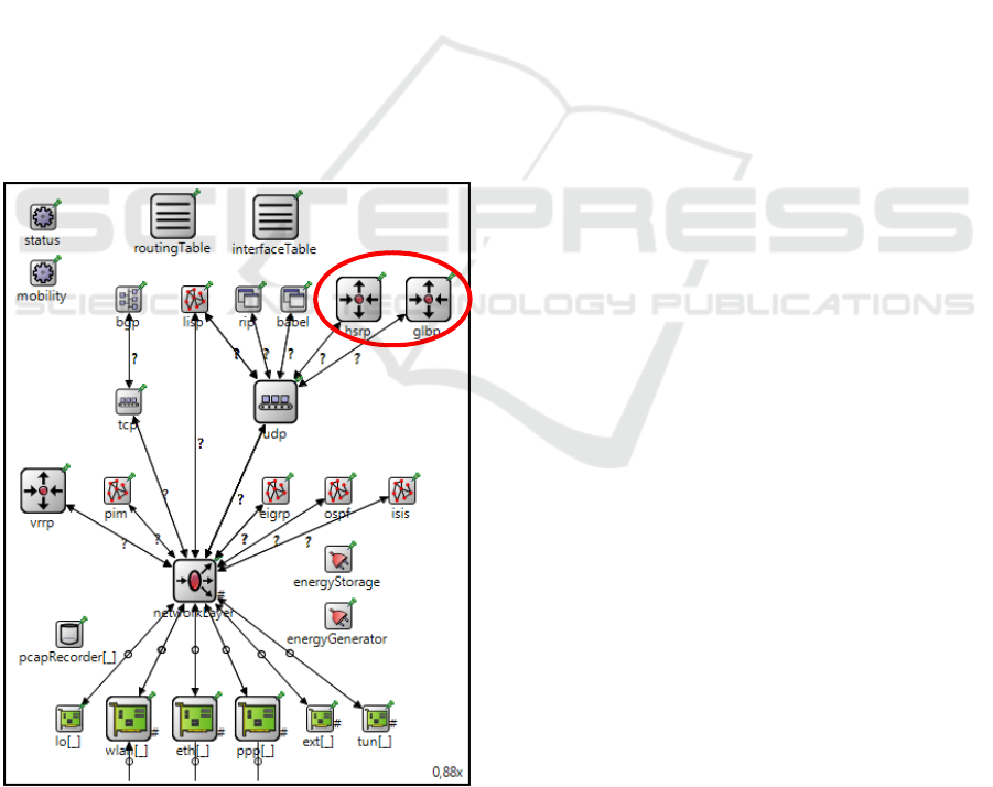
Figure 1: ANSARouter structure.
During the ANSA project run, we have extended
available simple router node with additional
functionality – support for various routing (e.g., RIP,
EIGRP, Babel) or neighbor discovery (e.g.,. CDP,
LLDP) protocols. The resulting ANSARouter
component is a compound module integrating all
expected functionality in a single programmable
simulation module that adopts a Cisco-style
representation of configuration, textual outputs (e.g.,
routing table format) and debugging information.
This paper discusses HSRP and GLBP protocol
implementation and their integration as new UDP
application modules to ANSARouter. The
simplified schema showing this integration is
depicted in Figure 1.
3 PRINCIPLES OF FHRP
This section provides a description of principles of
both HSRP and GLBP. It includes the format of
protocol messages, algorithms of leading router
selection, handling of addresses and involved timers.
Based on this, we provide high-level design overview
of relevant (sub)modules so that other users and
researchers may easily follow the design and/or
extend the modules with additional functionality, e.g.,
authentication, or incorporate them in other
simulation modules.
3.1 General FHRP Operation
First, we describe general operation of any First-hop
redundancy protocol. The basic principle is that
clustered redundant routers form an FHRP group,
which acts as a single virtual router with own virtual
IP address. Within the group, a single router is elected
as the coordinator based on announced priority.
Higher priority means superior willingness to become
a coordinator. In the case of equal priorities between
two candidates, a router with the higher IP address is
preferred. The election process may be preemptive or
non-preemptive. Preemption means that the router
with the highest priority always acquires the role of
coordinator even if the coordinator already exists.
Hosts have configured virtual IP address as their
default gateway. The coordinator responds to
ARP Requests or ND Solicitation for virtual IP with a
special reserved virtual MAC address. Whenever
FHRP group changes to a new coordinator, ARP
Gratuitous Reply or unsolicited ND Advertisement is
generated in order to rewrite association between the
interface and reserved MAC in CAM table(s) of
interim switch(es). This allows transparent switch of
coordinators for hosts during the outage.
SIMULTECH 2017 - 7th International Conference on Simulation and Modeling Methodologies, Technologies and Applications
332

Although both considered protocols offer
authentication of messages, the best practice is to
avoid any FHRP authentication configuration (Nadas,
2010). The risk of authentication misconfiguration is
that the network can operate more coordinators at the
same time, which causes non-deterministic behavior,
asymmetric flows or even black holing of traffic.
3.2 HSRP: Theory of Operation
The complete Hot Standby Router Protocol
specification is proprietary and not officially
published by Cisco Inc. However, some information
may be reconstructed from various public sources
such as RFC 2281 (Li et al., 1998), patent US8213439
B2 (Natarajan, 2004), and online pages (Cisco
Systems, 2009), (Cisco Systems, 2016).
From a group of candidate routers, HSRP elects
so-called Active router based on priority (in the
range from 0 to 255 with default value 100). The
Active router plays the role of a coordinator as
described in the previous subsection. The HSRP
election process is by default non-preemptive. The
HSRP group member with the second highest priority
(named Standby router) backs up the functionality
of the Active router. Only Active router forwards
traffic from the hosts. All other HSRP routers
periodically check the operability of Active node and
Standby node waiting to substitute them.
HSRP exists in two versions. Both versions
leverage UDP on port 1985 as the transport protocol.
HSRPv1 delivers redundancy of IPv4 default
gateway. HSRPv1 sends control messages to (all
routers) multicast address 224.0.0.2. HSRPv1
employs 8 bit long HSRP group identifier (values in
the range from 0 to 255) unambiguous for a single
interface/link. HSRPv1 virtual MAC has syntax
00:00:0c:07:ac:XX, where last byte’s XX is equal to
8 bits long HSRPv1 virtual group identifier. HSRPv2
extends functionality to achieve the sub-second
switchover between gateways and supports IPv6.
HSRPv2 routers send multicast messages using IPv4
address 224.0.0.102 or IPv6 address ff02::66.
HSRPv2 offers 12-bit long HSRP group identifier
(values in the range from 0 to 4095) accommodated
in the virtual MAC address of the form
00:00:0c:9f:fX:XX, where XXX is HSRPv2 group
identifier. HSRPv1 uses a different packet format
compared to HSRPv2 which employs type-length-
value protocol field approach.
Protocol fields Op Code in both headers specify
the type of HSRP message:
Hello – HSRP Hello messages notify other
members of the HSRP group about sender’s
parameters. Based on this parameters, the election
of Active and Standby occurs. After the election,
only Active and Standby routers generate any
HSRP messages;
Coup – If HSRP group is configured with
preemption, then the new group member with the
highest priority announces its right to become
Active router with HSRP Coup;
Resign – Group member, which no longer wants
to be Active, sends HSRP Resign message and
abstains from its role;
Advertisements – HSRP devices use this message
to inform about their group state activity or
passivity for ICMP redirects.
HSRP works with two timers which values are also
part of HSRP header. These timers must be
synchronized within the whole HSRP group.
Hellotime is the period between two consecutive
HSRP Hellos. Hellotime default value is 3 seconds.
Each HSRP group member maintains two Holdtimers
– one for Active and one for Standby router. If
Holdtime expires, Active/Standby is considered
unreachable, and election process is initialized.
Holdtime is reset with the each reception of HSRP
Hello. Suggested Holdtime value is at least 3× larger
than Hellotime in order to provide enough time for
any delayed
HSRP Hello to reach recipients.
Holdtime default value is 10 seconds.
Describing HSRP in more detail is beyond the
scope of this paper. To design a simulation model of
HSRP we have created a finite-state machine (FSM)
outlining overall HSRP functionality. HSRP process
transits through following states:
Init – There is single HSRP instance per group per
interface, which is being (re)initialized;
Learn – HSRP process can be started with
incomplete configuration. Group member learns
missing parameter values from received HSRP
Hellos during this state.
Listen – Passive member of HSRP group checks
availability of current Active/Standby and listens
for HSRP Hellos from these routers;
Speak – Router considers itself as a new candidate
for Active or Standby router role and periodically
announces candidacy via HSRP Hellos;
Standby – A single member from HSRP group
acts as a watch dog of Active router. Standby can
swiftly transit from this to Active state substituting
functionality of current Active;
Active – A single member with the superior
parameters (i.e., priority and IP address) remains
in this state as long as it serves as the Active router
for a group.
First-hop Redundancy Protocols in Omnet++
333

3.3 HSRP: Design
In OMNeT++, we have developed HSRPv1 as HSRP
compound module implementing IUDPApp
interface. This allows cooperation with UDP module
and the rest of modeled TCP/IP stack within
ANSAINET framework. The structure is depicted in
Figure 2.
Figure 2: HSRP simulation module structure.
HSRP is the container, which dynamically
instantiates HSRPVirtualRouter submodules for
each HSRP group based on scenario configuration.
HSRP model cooperates with InterfaceTable
and ARP modules. HSRPVirtualRouter sets up
timer values (i.e., *Timer self-messages) and HSRP
group attributes (i.e., priority, group identifier, virtual
IP address or HSRP state progress) according to
initial configuration and simulation run outcomes.
3.4 GLBP: Theory of Operation
Once again full specification of Gateway Load
Balancing Protocol is a part of the Cisco’s intellectual
property. Nevertheless, the most important parts are
in publicly available patent US7881208 B1 (Nosella
and Wilson, 2001), book (Hucaby, 2014) and online
sources (Cisco Systems, 2009).
The main difference between GLBP and
HSRP/VRRP is that GLBP offers dynamic load
balancing of the traffic. To accomplish this goal,
GLBP group may have more than one active router
for forwarding the clients’ communication. These
routers are called Active Virtual Forwarders
(AVF), and each GLBP group may contain four
AVFs at the most. AVFs are chosen from GLBP
group based on weight parameter. The weight is
configurable (default value is 100), where higher
means the better probability of being used as client’s
gateway. Each AVF has usually assigned a distinct
virtual MAC address; it may have temporary more
than one virtual MAC during AVF outages and
network convergence. A single device called Active
Virtual Gateway (AVG) is elected from GLBP
group to act as a usual FHRP coordinator which
responds to clients’ IP-to-MAC address resolutions.
AVG is chosen in a similar fashion as HSRP’s Active
router – device with the highest priority is elected as
AVG. AVG can act as AVF simultaneously. All non-
AVG and non-AVF GLBP members are backing up
the role functionality.
GLBP offers three load balancing schemes how
AVG is responding to client’s virtual IP address
resolutions:
Round-robin – AVFs are used in sequential fixed
order guaranteeing the same load;
Weighted – AVFs are chosen proportionally
according to weight.
Host-dependent – AVFs are used
deterministically based on source MAC address
which guarantees that the same client will always
use the same AVF.
There is only one GLBP version that operates over
UDP on port 3222. GLBP group members exchange
GLBP messages by employing multicast
communication on addresses 224.0.0.102 and
ff02::66. AVF is assigned with virtual MAC address
in format 00:07:b4XX:XX:YY, where XXXX is 12
bits long GLBP group identifier (between 0 and
4095), and YY is 8 bits long AVF identifier (in the
range from 01 to 04). GLBP provides redundancy for
both IPv4 and IPv6 default gateways. In the case of
IPv6, Cisco offers both link-local and global unique
gateway addresses.
All GLBP messages start with the same common
header followed by message specific protocol fields.
GLBP recognizes three message type-length-value
(TLV) parts:
Hello – GLBP Hello messages are being used as
keepalives for AVG and AVF functionality;
Request-Response – These messages are
exchanged between AVG and AVFs to govern
AVF functionality of GLBP group members.
GLBP Resign is special subtype of GLBP
Request-Response, which is used by AVF to
denounce its role;
Auth – This message contains MD5 authentication
data.
GLBP works with four timers. Hellotime and
Holdtime are analogous to timers with the same
names as in HSRP. These timers verify AVG and
AVFs operability via the periodic exchange of GLBP
Hello messages. Default Hellotime is set to 3 seconds;
default Holdtime value is 10 seconds. If AVG fails
then a new one is elected. If AVF fails then AVG
assigns AVF’s virtual MAC to a new AVF. During
Redirect timer period, AVG still announces AVF’s
virtual MAC to clients, where clients’ traffic is being
redirected to substitute AVF. Redirect is reset on
AVG with each AVF’s GLBP Hello and default
Redirect period is 600 seconds long. After Redirect
expires, AVG stops announcing failed AVF’s virtual
SIMULTECH 2017 - 7th International Conference on Simulation and Modeling Methodologies, Technologies and Applications
334

MAC address and starts Timeout timer. After Timeout
expires, AVG removes failed AVF and its virtual
MAC address completely from load balancing
process. The default value for Timeout is 14 400
seconds (4 hours).
Because of the complexity of GLBP, there are two
FSMs describing GLBP functionality. The first FSM
is for the election of virtual gateway (VG), where
GLBP group members transit between these states:
VG Disabled – There is a single GLBP instance
per group per interface, which currently does not
have virtual IP address assigned;
VG Init – GLBP group configuration is
incomplete similar to Learn state for HSRP;
VG Listen – Group member listens to VG’s GLBP
Hellos. Router is ready to swiftly progress from
this state to VG Speak in case of Active or Standby
VG outage;
VG Speak – Group member announces itself via
GLBP Hellos as a candidate for Active VG or its
substitution;
VG Standby – Only single member of GLBP
group acts as a Standby VG backing up AVG’s
functionality (similarly to HSRP Standby);
VG Active – A single group member is in this state
acting as a current GLBP’s AVG.
All GLBP members maintain state (e.g., assigned
virtual MAC, state, reachability) for each of existing
AVFs. The second FSM governs virtual forwarded
(VF) election and consist of following states:
VF Disabled – Transitional state for group
members without virtual MAC address;
VF Init – Group member has virtual MAC address
assigned but is misses other parameters (e.g.,
timers);
VF Listen – Member of GLBP group checks
GLBP Hellos from AVF ready to replace it in case
of outage;
VF Active – Group member forwards client’s
traffic as long as it remains in this state. Each
virtual MAC has primary and secondary VF.
3.5 GLBP: Design
We have designed GLBP in a similar fashion as
HSRP. GLBP compound module implements
IUDPApp interface and spawns
GLBPVirtualRouter instances. The module
structure is depicted in Figure 3. Comparing to HSRP,
GLBP maintains additional timers (associated both
with AVG and AVFs) and more abstract data
structures (e.g., who is AVF, what is current AVF
state, which virtual MACs are assigned to AVF).
Figure 3: GLBP simulation module structure.
4 VERIFICATION AND
VA L I D AT I O N
This section contains information about verification
and validation of implemented HSRP and GLBP
simulation modules. A rich collection of validation
scenarios and achieved results can be found along
with the source codes of simulation models.
Simulation models verification was conducted
using a traditional approach employing code review,
debugging and documentation (Law, 2014). We have
found that simulation models of both protocols
represent their corresponding specifications, namely,
the format of messages, configuration parameters
meaning, and the functionality in all tested cases.
In simulation validation, we have measured the
accuracy of simulation models to real
implementations on Cisco devices. As a part of this
activity, we have set up same network scenarios in
both simulator and the real environment. As a source
of information, we analyzed packets exchanged
between devices and debugging outputs of related
processes. We built the test-bed environment from
Cisco 7204 routers running IOS version c7200-
adventerprisek9-mz.152-4.M2 and host stations with
Windows 7 operating system.
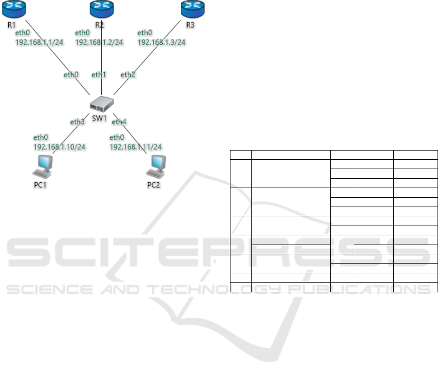
Figure 4 shows the basic topology used for
validation. It consists of three ANSARouter
instances (marked R1, R2, and R3) providing
HSRP/GLBP functionality and two ANSAHost
instances (PC1 and PC2). All devices are in the
common LAN segment with network address
192.168.1.0/24 interconnected by switch SW1
(simulated using EtherSwitch module). All
routers form FHRP group with identifier 0, where
each router uses default priority value. Preemption is
disabled within HSRP group. PC1 and PC2 are using
virtual default gateway with address 192.168.1.254.
Using this scenario, we perform validation for
both newly implemented simulation models. In the
first subsection, we focus on HSRP validation
scenario, in the second on GLBP. For both protocols,
we are interested in observing: 1) the process of
First-hop Redundancy Protocols in Omnet++
335
coordinator election; 2) scheduled coordinator outage
and subsequent FHRP group convergence
compensating failure; and 3) coordinator connection
reestablishment.
Figure 4: HSRP/GLBP testing topology.
4.1 HSRP: Validation
The first part of HSRP validation describes election
of Active and Standby routers and is aligned with
initialization of HSRP processes (just like in the case
of freshly booted routers) on R1, R2, and R3. We can
observe following FSM transitions and message
exchanges (depicted as phases н1-7):
н1) All routers transit from Init to Listen state in order
to determine whether there are already Active and
Standby routers available on their network
segment;
н2) During the first phase lasting one Holdtimer,
routers did not receive any HSRP Hello. Hence,
they transit from Listen to Speak state and start
election process after Holdtimers expire. All
routers generate HSRP Hello messages
announcing itself as a possible Standby candidate;
н3) R1 and R2 switch back to Listen state as soon as
they receive R3’s HSRP Hello because this
message announces R3 as the best Standby
candidate because of its highest IP address;
н4) R3 establishes itself as a Standby router after a
Holdtime period of waiting to potential better
HSRP Hellos. Further, R3 immediately upgrades
to Active router in order to overtake a missing
role;
н5) R1 and R2 meantime transit again to Speak
announcing themselves as candidates for Standby
router;
н6) R1 abstain from election, when it receives
superior (based on R2’s higher IP address) HSRP
Hello, and falls back to Listen;
н7) R2 becomes a new Stanby router by transiting
from Speak to Standby after one Holdtimer.
For all phases, we measured timestamps in order to
compare the accuracy of the simulation model to a
real implementation. Table 1 presents measured
results. Column with header “Ph”(ase) binds the
previous description with table content. Column
marked “Transition” denotes FSM progress of a given
router in column “D”(evice).
Table 1: HSRP timestamps during election of coordinator.
Ph Transition D Sim [s] Real [s]
н1 Init → Listen
R1 0.000 0.012
R2 0.000 0.000
R3 0.000 0.016
н2 Listen → Speak
R1 10.000 11.568
R2 10.000 11.540
R3 10.000 10.448
н3 Speak → Listen
R1 10.000 12.272
R2 10.000 12.740
н4
Speak → Standby
R3
20.000 20.016
Standby → Active 20.001 22.160
н5 Listen → Speak
R1 30.000 22.144
R2 30.000 30.324
н6 Speak → Listen R1 30.001 31.060
н7 Speak → Standby R2 40.000 42.164
The second presented HSRP validation tracks
events around interface failure between R3 (current
Active) and SW1. Following message exchange
occurs:
н8) The last R3’s HSRP Hello is heard on common
LAN segment which resets Holdtimers on R1 and
R2. Link between R3 and SW1 goes down;
н9) R2 transits from Standby to Active state and
becomes a new Active router. Immediately after
this, R2 sends ARP Gratuitous Reply to rewrite
MAC association on CAM table of SW1;
н10) Because there is no Standby router on the
segment, R1 transits from Listen to Speak state.
R1 generates HSRP Hellos announcing itself as a
candidate. After one Holdtime period, R1 transits
from Speak to Stanby state, and it is elected as a
new Stanby router.
Table 2 outlines comparison of message confluence.
All intercepted traffic (in column “Message”)
relevant to R2’s control plane is grouped by the phase
(in column “Ph”) in which it occurred. The column
“D” specifies the original sender of the control
SIMULTECH 2017 - 7th International Conference on Simulation and Modeling Methodologies, Technologies and Applications
336

message. The beginning of phase н8 is aligned with
the reception of the last R3’s HSRP Hello received.
Message label also show in which HSRP state was a
sender.
Table 2: HSRP timestamps during interface outage.
Ph Message D Sim [s] Real [s]
н8
Hello (Active) R3 0.000 0.000
Hello (Standby) R2
2.000
5.000
8.000
2.108
4.748
7.244
н9
Hello (Active)
R2
10.000 10.172
ARP Grat. Reply 10.000 10.293
Hello (Active)
13.000
16.000
19.000
13.036
15.484
17.964
н10
Hello (Speak) R1
10.000
13.000
16.000
19.000
10.120
12.812
15.376
17.928
Hello (Standby) R1 20.000 19.796
The third part focus on events that happen when
the link between R3 and SW1 re-establishes
connectivity. Phases are described in the following
list:
н11) R3-SW1’s interface goes up, and R3 reinitializes
its HSRP process from Init to Listen state;
н12) After few moments, R3 receives HSRP Hello
messages from R2 (current Active) and R1
(current Standby). Because R3 configuration is
superior to R1, it transits from Listen to Speak
state to take over Standby router role;
н13) R1 transits from Standby to Listen state as first
R3’s HSRP Hello arrives to R1;
н14) After one Holdtimer period, R3 is elected as a
new Standby router. R2 remains an Active router
due to the configured preemption.
Table 3 denotes timestamps of above-described
transitions. The beginning of phase н11 is aligned
with the restart of HSRP process on R3.
Table 3: HSRP timestamps during connectivity restoration.
Ph Transition D Sim [s] Real [s]
н11 Init → Listen R3 0.000 0.000
н12 Listen → Speak R3 0.001 0.876
н13 Speak → Listen R1 0.002 0.968
н14 Speak → Standby R3 10.000 11.164
4.2 GLBP: Validation
The first part of GLBP validation consists of AVG
and AVF election. Event tracking is aligned with
initialization of GLBP processes in R1-3. Transitions
during this time are listed as phases ԍ1-7:
ԍ1) GLBP group members transit from VG Init to VG
Listen state upon successful start of GLBP process
on interface;
ԍ2) After one Holdtimer, all routers switch to VG
Speak and generate GLBP Hello announcing their
candidacy;
ԍ3) As soon as R1 and R2 receives R3’s GLBP Hello,
they fall back to VG Listen state
ԍ4) After one Holdtime period, R3 is elected as a new
AVG. Comparing to HSRP coordinator election,
GLBP router can immediately transit VG Active
state;
ԍ5) There is no one backing up the functionality of
AVG. Hence, R1 and R2 transits from VG Listen
to VG Speak after successful election of R1 when
Holdtimer expires generating GLBP Hellos to
GLBP multicast group;
ԍ6) R1 transits back to VG Listen after it receives
superior GLBP Hello from R2;
ԍ7) One more Holdtimer expiration and R2 wins the
election for a new Standby VG, which means the
transition from VG Speak to VG Standby.
Table 4: GLBP timestamps during election of coordinator.
Ph Transition D Sim [s] Real [s]
ԍ1 Init → Listen
R1 0.000 0.000
R2 0.000 0.576
R3 0.000 1.008
ԍ2 Listen → Speak
R1 10.000 10.012
R2 10.000 10.584
R3 10.000 11.020
ԍ3 Speak → Listen
R1 10.000 10.560
R2 10.000 11.216
ԍ4 Speak → Active R3 20.000 11.820
ԍ5 Listen → Speak
R1 20.000 11.132
R2 20.000 11.480
ԍ6 Speak → Listen R1 20.000 11.784
ԍ7 Speak → Standby R2 30.000 21.496
The second part briefly mentions AVF election
process. If we have GLBP group with less than five
routers, all group members are elected as AVFs.
Together with GLBP Hello TLVs, routers append
also GLBP Request/Response into message
periodically exchange every Hellotime period. Each
VF FSM transits from VF Init to VF Listen upon the
start of GLBP process. GLBP members start to
exchange GLBP Request/Response TLVs announcing
themselves as potential candidates. Each router
chooses (based on unknown hash function) one AVF
and starts advertise itself as either primary
(priority 167) or secondary (priority 135) candidate
for AVF. After one Holdtimer period since the first
GLBP Request/Response, router transits from VF
Listen to VF Active state. Unfortunately, due to the
First-hop Redundancy Protocols in Omnet++
337

currently unknown algorithm for choosing primary or
secondary AVF priorities, we cannot provide a
reproducible comparison between simulated and real
scenario. Nevertheless, we have implemented own
deterministic selection algorithm suitable for
repeating simulations.
The third part focus on the handling of PC1 and
PC2 communication. We had scheduled pings to
default virtual gateway 192.168.1.254. Because
testing topology is configured with a round-robin load
balancing scheme, AVFs are being deterministically
chosen by AVG when responding to client’s ARP
Request. For both simulated and real network, AVG
rotated virtual MACs in ARP Replies delegating PC1
and PC2 to different AVFs.
4.3 Tests Summary
The correlation of transitions and messages between
simulation and real network suggests correctness of
our HSRP and GLBP implementations.
Comparison between the operation of our
simulation modules and referential implementation
shows slight time variations in Table 1, 2 and 3. The
main cause is an oscillation of built-in jitters in Cisco
implementation, which randomly variates ±20 % of
preconfigured value in order to avoid alignment of
several timeout events of different processes at the
same time (Cisco Systems, 2016). Other factors
influencing variation are: 1) control-plane processing
– TCP/IP stack packet handlings are not same;
2) hardware processing – it is a challenge to evaluate
delay impact of component interrupts and dedicated
hardware acceleration in simulation; 3) inaccuracy of
event alignment and timing in a real network.
Table 4 discrepancy between simulated and real
scenario is caused by GLBP optimization available in
newer Cisco IOS versions. This optimization allows
routers to send GLBP messages even during VG
Listen state. Hence, AVG is reliably determined
sooner which speeds up the convergence of GLBP
group. Optimization was available neither in GLBP
functionality description (Cisco Systems, 2009) nor
original Cisco IOS (c2691-entservicesk9-mz.124-16)
followed during the model development.
Because of this, we conducted multiple
measurements on referential implementation for each
scenario. Only test runs with the similar order of
timeout expiration between simulated and real
network are presented in this section. We uploaded
debug baselines and packet captures from these
measurements on a dedicated web page
(GitHub/ANSAwiki, 2017) to provide a reference for
result reproduction.
Finite-state machine transitions and routing
outcomes are same between real and simulated
scenarios.
5 CONCLUSION
In this paper, we provided an analysis and description
of two first-hop redundancy protocols – HSRP and
GLBP. We designed and implemented simulation
modules of these two protocols within OMNeT++
discrete-event simulator. We tested and verified
functionality and accuracy of our models in
comparison with the real network running referential
implementation. To summarize the contribution of
this paper:
Despite proprietary nature and limited public
information sources, we collected the core
knowledge about protocol specification and
functionality of HSRP and GLBP. Moreover, we
have created finite-state machines describing their
functionality based on the previous information.
The FSM can be reused by other researchers and
programmers as a reference when developing an
own independent implementation.
Subsequently, we have created new FHRP
simulation modules for OMNeT++. To our
knowledge, these models are the first full-fledged
simulator implementations for OMNeT++ that
complies with the Cisco reference and provides
reasonable accuracy. Moreover, modules can be
easily extended and reconfigured for any user
scenario.
Based on our past work and the presented results we
plan to perform: 1) comparative study of HSRP,
GLBP and VRRP measuring convergence speed,
protocol metrics, and overhead; 2) enhancing the
functionality of VRRP and HSRP with IPv6 support.
More information about the ANSAINET project
is available on the homepage (Brno University of
Technology, 2017). All source codes including HSRP
and GLBP implementations could be downloaded
from GitHub repository (GitHub/ANSA, 2017)
ACKNOWLEDGEMENTS
This work was supported by the Brno University of
Technology organization and by the research grant
FIT-S-14-2299.
SIMULTECH 2017 - 7th International Conference on Simulation and Modeling Methodologies, Technologies and Applications
338

REFERENCE
Arnaud, A., 2017. Wiki - uvrrpd - Forge Evolix. [Online]
Available at: https://forge.evolix.org/projects/uvrrpd
/wiki [Accessed March 2017].
Bourgeois, F., 2017. GitHub - fredbcode/Vrrpd. [Online]
Available at: https://github.com/fredbcode/Vrrpd
[Accessed March 2017].
Brno University of Technology, 2017. ANSA Project.
[Online] Available at: https://ansa.omnetpp.org/
[Accessed March 2017].
Brocade Communications Systems, 2015. VRRP and
VRRP-E.[Online] Available at: http://www.brocade.
com/content/html/en/configuration-guide/NI_05800a_
ROUTING/GUID-95F520A1-661F-42FB-9A7E-
A58B3CA84D37.html [Accessed March 2017].
Cassen, A., 2016. Keepalived for Linux. [Online]
Available at: http://www.keepalived.org/index.html
[Accessed March 2017].
Cisco Systems, 2009. GLBP - Gateway Load Balancing
Protocol. [Online] Available at: http://www.cisco.com
/en/US/docs/ios/12_2t/12_2t15/feature/guide/ft_glbp.h
tml [Accessed March 2017].
Cisco Systems, 2009. Understanding and Troubleshooting
HSRP Problems in Catalyst Switch Networks. [Online]
Available at: http://www.cisco.com/c/en/us/support/do
cs/ip/hot-standby-router-protocol-hsrp/10583-62.html
[Accessed March 2017].
Cisco Systems, 2016. First Hop Redundancy Protocols
Configuration Guide, Cisco IOS XE Release 3S -
Configuring HSRP [Cisco IOS XE 3S]. [Online]
Available at: http://www.cisco.com/c/en/us/td/docs/
ios-xml/ios/ipapp_fhrp/configuration/xe-3s/fhp-xe-3s-
book/fhp-hsrp.html#GUID-33A214D6-87AC-4D17-
87D3-297FA963B4EB [Accessed March 2017].
Cisco Systems, 2017. Download Packet Tracer | Cisco
NetAcad. [Online] Available at: https://www.netacad.
com/about-networking-academy/packet-tracer/
[Accessed March 2017].
GitHub/ANSA, 2017. ANSAINET extends INET framework
for OMNeT++. [Online] Available at: https://github.
com/kvetak/ANSA [Accessed March 2017].
GitHub/ANSAwiki, 2017. SimulTech 2017 Results
Reproduction. [Online] Available at: https://github.
com/kvetak/ANSA/wiki/SimulTech-2017
[Accessed March 2017].
Hewlett Packard Enterprise, 2012. HP 5920 & 5900 Switch
Series High Availability Configuration Guide - display.
[Online] Available at: http://h20566.www2.hpe.com/
hpsc/doc/public/display?sp4ts.oid=5221896&docLoca
le=en_US&docId=emr_na-c03187009. [Accessed
March 2017].
Hucaby, D., 2014. Gateway Load Balancing Protocol. In:
CCNP Routing and Switching SWITCH 300-115
Official Cert Guide. Indianapolis, Indiana, USA: Cisco
Press, pp. 397-405, ISBN-10:1-58720-560-2.
IETF, 2003. Mailing-list - RE: [VRRP] HSRP, conditions
of use. [Online] Available at: https://www.ietf.org/
mail-archive/web/vrrp/current/msg00342.html
[Accessed March 2017].
Juniper Networks, 2013. [ScreenOS] How to configure
HSRP and VRRP on ScreenOS devices that are running
in the Transparent mode. [Online]
Available at: https://kb.juniper.net/kb7109
[Accessed March 2017].
Kaur, I. & Bajaj, H., 2013. Performance Evaluation of
HSRP Protocol for Wireless Network for Fault
Tolerance to Improve Quality of Service. International
Journal of Engineering and Innovative Technology,
November, pp. 267-269, ISSN: 2277-3754.
King, R. & Sanchez, E., 2013. Simulative Comparison of
HSRP & VRRP. [Online] Available at: https://www.
academia.edu/12395848/Undergraduate_Major_Projec
t_Simulative_Comparison_of_HSRP_and_VRRP
[Accessed March 2017].
Law, A., 2014. Simulation Modeling and Analysis.
Industrial Engineering and Management ed. New York,
USA: McGraw-Hill, ISBN-10:0073401323.
Li, T., Cole, B., Morton, P. & Li, D., 1998. RFC 2281 -
Cisco Hot Standby Router Protocol (HSRP). [Online]
Available at: https://tools.ietf.org/html/rfc2281
[Accessed February 2017].
MikroTik, 2015. Manual:Interface/VRRP. [Online]
Available at: https://wiki.mikrotik.com/wiki/
Manual:Interface/VRRP [Accessed March 2017].
Nadas, S., 2010. RFC 5798 - Virtual Router Redundancy
Protocol Version 3 for IPv4 and IPv6. [Online]
Available at: https://tools.ietf.org/html/rfc5798#page-
33 [Accessed March 2017].
Natarajan, S., 2004. Method and system for managing a
network having an HSRP group. United States of
America, Patent No. US8213439 B2.
Nosella, T. J. & Wilson, I. H., 2001. Gateway load
balancing protocol. United States of America, Patent
No. US7881208 B1.
Veselý, V. & Ryšavý, O., 2015. Map-Cache
Synchronization and Merged RLOC Probing Study for
LISP. The International Journal on Advances in
Intelligent Systems, pp. 494-506, ISSN 1942-2679.
First-hop Redundancy Protocols in Omnet++
339
