
Designing Fingers in Simulation based on Imprints
Lukas Christoffer Malte Wiuf Schwartz
1
, Adam Wolniakowski
2
, Andrzej Werner
2
,
Lars-Peter Ellekilde
1
and Norbert Kr
¨
uger
1
1
The Maersk McKinney-Moller Institute, University of Southern Denmark, Odense, Denmark
2
Department of Mechanical Engineering, Białystok University of Technology, Białystok, Poland
Keywords:
Simulation, Gripper Design, Optimization, Grasping.
Abstract:
Gripper design is nowadays an area of ongoing research activity. The problem of creating a generic and auto-
mated gripper design approach tailored for a specific task is still far from solved. In this paper, we propose a
new method of generating finger cut-outs aimed at simplifying the design process of doing so. This method
takes root in the idea of using the imprint to produce the finger geometry. We furthermore provide a verifica-
tion of our newly introduced imprinting method and a comparison to the previously introduced parametrized
geometry method. This verification is done through a set of grasping experiments performed in simulation on
two objects with geometry features based on those found in industrial setting.
1 INTRODUCTION
A large portion of industrial tasks that are (or can)
be automatized through the use of robots consists of
handling, manipulating, moving and placing of ob-
jects. There are some challenges that are associated
with strict requirements on the process quality since
the objects have to be (Honarpardaz et al., 2017):
1) grasped robustly and successfully,
2) moved rapidly in effort to reduce the cycle time,
and
3) then placed precisely.
All of this is done in presence of uncertainties,
which are due to factors like sensor calibration, im-
precise end-effectors or the flexibility of objects and
their environment. In addition, new grasping solu-
tions have to be adopted quickly, in order to respond
to changing manufacturing processes in small and
medium sized productions, often encountered in the
industry.
In typical industrial cases, the gripper solutions
are commonly implemented starting with the selec-
tion of the gripper. The fingers are then designed
by experienced engineers with the usage of heuris-
tics, guidelines, experience and trial-and-error exper-
iments. The finished designs are often produced by
the user or system integrator, using additive manufac-
turing or CNC machines. The process is cumbersome
and demanding in terms of the cost and the time re-
quired to establish a working solution.
The use of 3D printing as gripper manufacturing
technique invites the creation of smart software solu-
tions to produce and optimize the finger geometries.
The increasing computational power available and the
development of robotic frameworks (such as Rob-
Work (Ellekilde and Jørgensen, 2010)) and physical
engines, such as ODE (Smith, 2008) and RWPhysics
(Thulesen and Petersen, 2016) facilitate the use of
dynamic simulation to replace the arduous trial-and-
error design process. The automation of design with
the use of flexible software tools is indeed a current
trend in industrial manufacturing and robotics.
In our previous work (Wolniakowski et al., 2017),
a gripper design method was introduced which uses
dynamic simulation in order to provide a quality esti-
mate of parametrized grippers. This allows for the fin-
ger designs to be automatically optimized. This previ-
ously described method, while flexible and allowing
for inclusion of task context information in the gripper
optimization process, suffers from rather complex re-
quirements on the amount of set-up and user input. In
particular, the user has to provide a basic idea for the
gripper structure in form of the geometry parametriza-
tion (which is then numerically optimized). An exam-
ple of how a geometry parametrization can look like
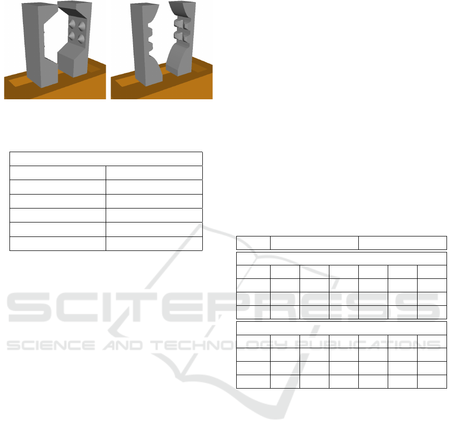
is seen as the left finger in Figure 1. This itself is
by no means trivial, and it can be easily seen that no
globally optimal gripper solution can be found when
304
Schwartz, L., Wolniakowski, A., Werner, A., Ellekilde, L-P. and Krüger, N.
Designing Fingers in Simulation based on Imprints.
DOI: 10.5220/0006441003040313
In Proceedings of the 7th International Conference on Simulation and Modeling Methodologies, Technologies and Applications (SIMULTECH 2017), pages 304-313
ISBN: 978-989-758-265-3
Copyright © 2017 by SCITEPRESS – Science and Technology Publications, Lda. All rights reserved
a insufficiently flexible parametrization is provided.
Defining the cut-out shape parametrization manu-
ally is particularly difficult and time consuming. In-
stead, the cut-out shape can be automatically gener-
ated based on the object’s imprint in the fingers. Fur-
thermore, the generated cut-out can be post-processed
in order to eliminate the grasped object’s pose uncer-
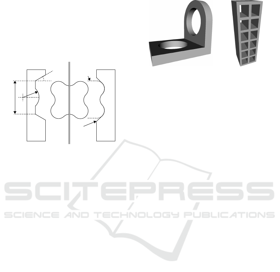
tainty (see the right finger in Figure 1).
Object
Paramatized
Imprint
imprint
post-
processing
a
w
r
d
Figure 1: The two different ways to design the fingers anal-
ysed in this work. On the left: the manual parametriza-
tion method (PFO, introduced previously in (Wolniakowski
et al., 2017)). On the right: the new imprint based method
(IFM).
In this work, we propose a method of generating
the parametrized cut-out profiles based on the grasped
object imprints. The method is an extension of the
previously presented idea (Wolniakowski et al., 2015)
that greatly reduces the user input required in setting
up the gripper optimization process. In doing so, this
development marks another step in creation of a fully
automated gripper design framework. The two finger
design methods can be used in conjunction utilizing
the synergy of the flexibility in selecting the custom
optimal finger shapes, while the cut-out shape is gen-
erated automatically to match the grasped object’s ge-
ometry.
The new cut-out shape generation method is tested
by comparing its performance with the previous
parametrized geometry optimization method in two
scenarios of grasping objects of complex shapes: the
bracket and the heatshield (see Figure 2). For each of
these objects, the optimized finger geometry is gen-
erated and subsequently their alignment capability is
tested in simulated grasp experiments.
The paper is organized as follows. First, in Sec-
tion 2, an analysis of the gripper design problem is
presented, summarizing the research published in the
field, and analysing several contemporary solutions
used in the industry. Next in Section 3, we present
our data-driven parametrized finger geometry genera-
tion method (Wolniakowski et al., 2017) and our new
(a) The bracket object. (b) The heatshield object.
Figure 2: The objects used in the gripper design experi-
ments.
method, based on the object imprint. In Section 4, the
performance of the two methods is compared when
designing gripper fingers for grasping two complex
objects. The fingers are then tested in simulations,
in order to determine the range of grasp uncertainties
that the designed grippers can compensate for. Fi-
nally, we present our conclusions in Section 6.
2 STATE OF THE ART
The most common gripper structure used in the in-
dustry nowadays is that of a parallel finger gripper.
A parallel finger gripper consists of a base which
provides the actuation (be it electric or pneumatic),
which is typically selected from an array of off-the-
shelf products and of two fingers. The fingers move
in a linear fashion in opposite directions until a cer-
tain position or force is achieved. The reason for the
widespread use of the parallel gripper design is its rel-
ative simplicity and flexibility. The adaptation to a
new context is usually done by designing and mount-
ing a new pair of fingers, tailored to fulfil the require-
ments of a specific task. Nowadays these fingers are
often designed and manufactured (e.g. printed) by the
system integrator or user. The process of gripper fin-
ger design is not a simple task, and an area of on-
going research.
An excellent literature review in the field of grip-
per design has been recently published by (Honarpar-
daz et al., 2017). They discuss the long-established
solutions and recent developments critically selected
from the database of thousands of articles. Other
similar reviews can be found in (Boubekri and
Chakraborty, 2002; Blanes et al., 2011).
The typical workflow involved in the design of
a new gripper solution can be described as follows
(Honarpardaz et al., 2017): 1) the requirements im-
posed on the task by the grasped object properties and
the task context is gathered, 2) a decision is then made
Designing Fingers in Simulation based on Imprints
305

on whether the grasps are performed using the force-
fit or form-fit method (Honarpardaz et al., 2017), and
3) the grasp sets are generated and analysed. The ac-
tual finger design is done after the optimal grasp has
been found, and iterated in a trial-and-error process
(testing e.g. unwanted collisions and grasp robust-
ness) until a solution is found that is good enough.
The area of gripper design research is obviously
closely connected with that of the research on grasp-
ing. As discussed above, the selection of suitable
grasps is an essential component of the design pro-
cess. In this field, contributions by (Borst et al., 2004;
Kraft et al., 2012; Li et al., 2007; Berenson et al.,
2007; Jørgensen and Petersen, 2010; Stulp et al.,
2011) can be noted, in which various quality measures
of the grasps space are considered. We make use of
these grasp quality objectives in our gripper quality
evaluation.
The process of gripper design is expensive in
terms of time, cost and the expertise required. Numer-
ous guidelines have been created, including heuris-
tics which can be applied to assist with the process.
These guidelines include, for example contributions
such as (Krenich, 2014; Causey and Quinn, 1998).
Many guidelines have been conveniently gathered in
a work concerning agility in manufacturing (Causey,
2003).
Numerous works have been published in which
the kinematic structure of the gripper that is subjected
to optimization (Cuadrado et al., 2002a; Lanni and
Ceccarelli, 2009; Cuadrado et al., 2002b; Ceccarelli
et al., 2002). In other works, modular or reconfig-
urable gripper jaws systems were proposed (Zhang
and Goldberg, 2006; Kolluru et al., 2000).
Recently, dynamic simulation has been proposed
as a tool to facilitate the replacement of a trial-and-
error process with much easier virtual experimenta-
tion. In (Ellekilde and Petersen, 2006) they proposed
the design of the gripper jaws based on the convex-
hull molding, in order to achieve robustness in terms
of grasped object pose uncertainty. The results have
been verified both in real-world experiments and in
simulation. Molding and imprinting is taken to be the
same in the cut-out generation process, the two terms
are therefore used interchangeably.
In (Wolniakowski et al., 2014), we introduced a
metric for the quality of a gripper design which takes
into account the conditions imposed by the task con-
text. We have subsequently worked on the formula-
tion of gripper design parametrization and optimiza-
tion methods (Wolniakowski et al., 2015), so that
the gripper finger design process could be automated.
This process was furthermore tested in various sce-
narios (Wolniakowski et al., 2017).
A new online tool by Schunk was recently made
available (Schunk, 2015). This tool uses the estab-
lished method of using the object molding on the fin-
ger, so that a new form-fit design can be created eas-
ily. The tool requires input from the user in terms of
the selection of a base finger shape, the expected pose
of the object and other relevant variables. This im-
plementation is protected by a patent (Schuster et al.,
2014). Molding has indeed been long used for grip-
per finger design (Velasco and Newman, 1998). The
major shortcomings of this method is the sensitivity
to uncertainties in the object shape and pose, and its
inapplicability to certain classes of objects.
In this work, a new imprinting method inspired by
the previous ideas within finger design using molds or
imprints is presented. We do not only use the profile
created by the inverse of the object’s geometry, but
also add profiles around the cut-out to facilitate the
guiding of the object into a stable position when the
pose uncertainties are present. Furthermore, simula-
tions are used as a tool to verify the designs.
3 METHODS
In this section, the gripper design optimization meth-
ods used in this work a described, starting with the
short primer on the parametrized geometry optimiza-
tion method introduced previously in (Wolniakowski
et al., 2017) (see Section 3.1). The new Imprint Fin-
ger Method (IFM) method is then introduced (see
Section 3.2), which builds upon the former by greatly
simplifying the process of finding the appropriate cut-
out parametrization for the grasped objects.
In both methods, the general workflow is similar
(see Figure 3). The common inputs required from the
user are: a 3D model of the object, the expected grasp
location (pose), and the task description (i.e. the ob-
ject position, the environment, uncertainties, gripper
structure, grasp success conditions, etc.) – see Fig-
ure 3a. In the first step, the environment representa-
tion has to be created (see Figure 3b), this was done
using the RobWork (Ellekilde and Jørgensen, 2010)
XML format. Next, the grasp set is generated by
perturbing randomly the grasp pose specified by the
user (see Figure 3c). Then, the gripper parametriza-
tion has to be provided by the user (see Figure 3d).
This can be done in the form of a OpenSCAD (Kin-
tel, 2009) script that contains a parametric model of
the finger geometry or using the hereby introduced
method (see Section 3.2). Finally, the simulation of
the generated grasps (see Figure 3f) is done repeat-
edly for different gripper designs proposed by the op-
timization procedure (see Figure 3e). The output con-
SIMULTECH 2017 - 7th International Conference on Simulation and Modeling Methodologies, Technologies and Applications
306

sists of the optimized gripper model (see Figure 3g).
The dynamic simulations were in both methods im-
plemented using the RobWork framework (Ellekilde
and Jørgensen, 2010) and its simulation package Rob-
WorkSim (Jørgensen et al., 2010). The physics en-
gine used in simulation is the Open Dynamics Engine
(ODE) (Smith, 2008).
Our new method allows for a significant reduction
in user input required through automating the gener-
ation of the finger geometry parametrization, thus re-
ducing the set-up time of the finger parametrization
and improving on the ease of use.
3.1 Parametrized Finger Optimization
(PFO)
In our previous work (Wolniakowski et al., 2017),
a method was introduced for computing the gripper
quality for a given task context using dynamic simu-
lation as a tool. Several Gripper Quality indices were
defined, capturing essential gripper properties neces-
sary to execute the grasping tasks successfully. These
quality measures are:
Success Index (S) which quantifies the overall suc-
cess rate of the executed grasps.
Coverage Index (C) which provides a measure of
the gripper versatility expressed as the size of the
successful approach vectors.
Robustness Index (R) defining the gripper perfor-
mance in presence of pose uncertainties.
Alignment Index (A) quantifying the size of pose
uncertainties for which the grasped object is still
forced by the gripper into a predictable pose.
Wrench Index (W) measuring the average robust-
ness of the grasps in terms of Grasp Wrench Space
metric (Ferrari and Canny, 1992).
Stress Index (T) representing structural robustness
of the gripper design.
Volume Index (V) based on the time and material
needed to produce the gripper fingers.
The details on the implementation of the quality in-
dex calculation can be found in (Wolniakowski et al.,
2017). The quality evaluation is based on simulat-
ing a number of grasps, generated either using heuris-
tic planning or generated stochastically with user-
provided uncertainty estimations.
These metrics was used in conjunction with a
gripper geometry parametrization method and an ar-
ray of numerical optimization techniques in order to
improve gripper finger designs automatically. The
objective function for the optimization is defined as
a weighted geometric average of individual indices
(Equation 1):
Q =
N
∏
i=1
q
w
i
i
!
1/
∑
N
i=1
w
i
(1)
where q = [S, C, R, A, W, T, V ] is the vector of the
seven gripper quality indices described above and the
w
1
, w
2
, ... are the respective weights.
The performance of the method was showcased
in several industry-based grasping scenarios (Wol-
niakowski et al., 2016). While this previously in-
troduced gripper design method (which will subse-
quently be referred to as the ”PFO method”) is ap-
plicable and flexible, it still requires the user to pro-
vide a lot of manual input in form of a custom ge-
ometry parametrization, decide on the weights of the
quality objective and the numerical optimization tech-
nique used. This problem is now targeted by automat-
ing the generation of the gripper cut-out, as described
in the following section.
3.2 Imprint Finger Method (IFM)
The generation of the cut-out for a finger takes basis
in the idea of pressing the object into a piece of soft
clay. Using the imprint of the object directly as a cut-
out is a poor solution since it requires a high degree
of pose certainty to place an object into its cut-out. To
improve the performance, the cut-out is modified to
get the final cut-out used to generate the finger.
4 RESULTS
In the experiments, the performance of the data-
driven gripper design and optimization methods for
grasping two different objects was compared. The
two selected objects: the bracket and the heatshield
are shown in Figure 2 . The objects were chosen as to
highlight the pros and cons of both considered meth-
ods (PFO and IFM) and to provide a reasonable de-
sign challenge. The bracket object was designed in a
fashion to make it difficult to generate the imprinted
fingers for it, due to the necessity of using the internal
grasp. The heatshield in turn poses a challenge for the
user designed cut-out parametrization: it is not a triv-
ial requirement to provide a simple (i.e. using only
a few free variables) parametrization that is flexible
enough for an object of complex geometry.
The object models were generated using the
OpenSCAD software. The bounding box dimensions
for the objects are 35 × 30 × 35 mm for the bracket
Designing Fingers in Simulation based on Imprints
307
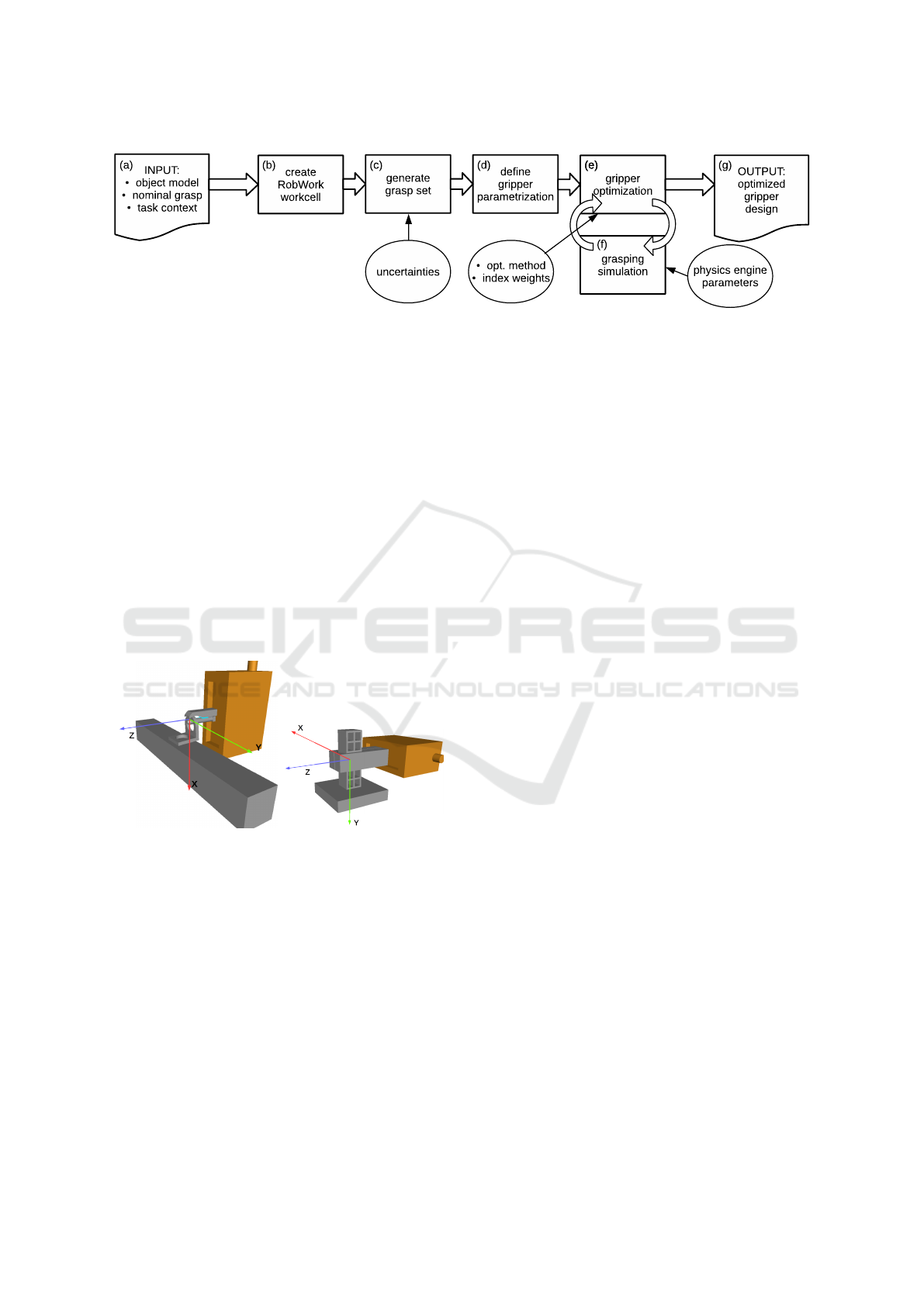
Figure 3: The workflow in using the parametrized gripper optimization methods.
object and 30 × 30 × 100 mm for the heatshield ob-
ject respectively. For the purpose of simulation, their
masses were assigned to be m
bracket
= m
heatshield
=
50g. The friction properties of the material were set
to correspond to printable plastic, with friction coef-
ficient between the gripper fingers (also printed out
of the plastic) and the object was µ = 0.4. The grip-
per was in the simulations set to use a force of 50N for
each grasp. The simulation used the Coulomb friction
model.
The task context for grasping in both of the sce-
narios is presented in Figure 4. The objects are placed
on corresponding fixtures and a nominal grasp (illus-
trated in Figure 4) is defined for both cases. The fig-
ure additionally shows the axes, which indicate the
direction along which the grasps were offset during
the subsequent grasp alignment experiments.
(a) The bracket grasp. (b) The heatshield grasp.
Figure 4: The nominal grasps defined for the test objects.
The grasp alignment experiments were performed
in the following way. Each of the objects was grasped
repeatedly with grasps offset from the nominal grasp
along one of the major Cartesian directions: X, Y and
Z and angles θ
x
, θ
y
and θ
z
around these axes. For each
of the grasps, the grasping result was assigned one of
the three outcomes: successful – when the object was
grasped and positioned correctly wrt. to the gripper in
terms of translation and rotation, misaligned – when
the object was grasped, but the position was not cor-
rect, and failure – when the object was not grasped
(due to, e.g. collision with the fixture, the object drop-
ping out of the gripper, simulation failure etc.).
The outcome was determined automatically in
simulation, based on the object and gripper poses as
well as the contact points recorded during the simula-
tion. The grasp alignment was tested using the condi-
tion Equation 2.
max(d
ang
· w
ang
,d
lin
· w
lin
) < ε
A
(2)
where d
ang
and d
lin
are the angular and linear displace-
ments from the expected pose to the grasp pose (in
degrees and millimetres respectively). w
ang
and w
lin
are user specified weights for respectively the angu-
lar and linear displacements and ε
A
is the threshold
below which the grasp is considered to be successful.
The pose and angle weights (w
ang
and w
lin
respec-
tively) are set to 0.25 and 1, and the threshold ε
A
is
set to 1 for both objects. The data on the performance
of the grippers in object alignment was subsequently
collected and processed.
For each of the scenarios, interesting ranges in
offset space were determined during the preliminary
simulation experiment round. The sampling and the
offset bounds were subsequently defined as shown in
Table 1. Altogether, 2772 grasping experiments were
executed in simulation: 1246 for the bracket object
and 1526 for the heatshield object.
4.1 Bracket Object Scenario
The gripper design optimization for the bracket sce-
nario was performed using the predefined gripper fin-
ger shapes (a block finger with dimensions 10 × 10 ×
50 mm, wrt. the coordinate axis in Figure 4(a), and
a round finger with a width and length of 10 × 50
mm) with cut-outs designed using (a) the PFO method
and (b) the IFM. Figure 5 shows the parametrization
scheme used to design the bracket object grasping fin-
gers with the use of the PFO method.
The fingers designed using the IFM were gener-
ated specifying the bracket as the imprint object and
the nominal grasp pose shown in Figure 4(a) being the
imprint pose (see Section 3.2). When designing the
finger for the inner grasp using the IFM, the bracket
was cut open. This was done because the method con-
siders the exterior of the object and by removing the
SIMULTECH 2017 - 7th International Conference on Simulation and Modeling Methodologies, Technologies and Applications
308
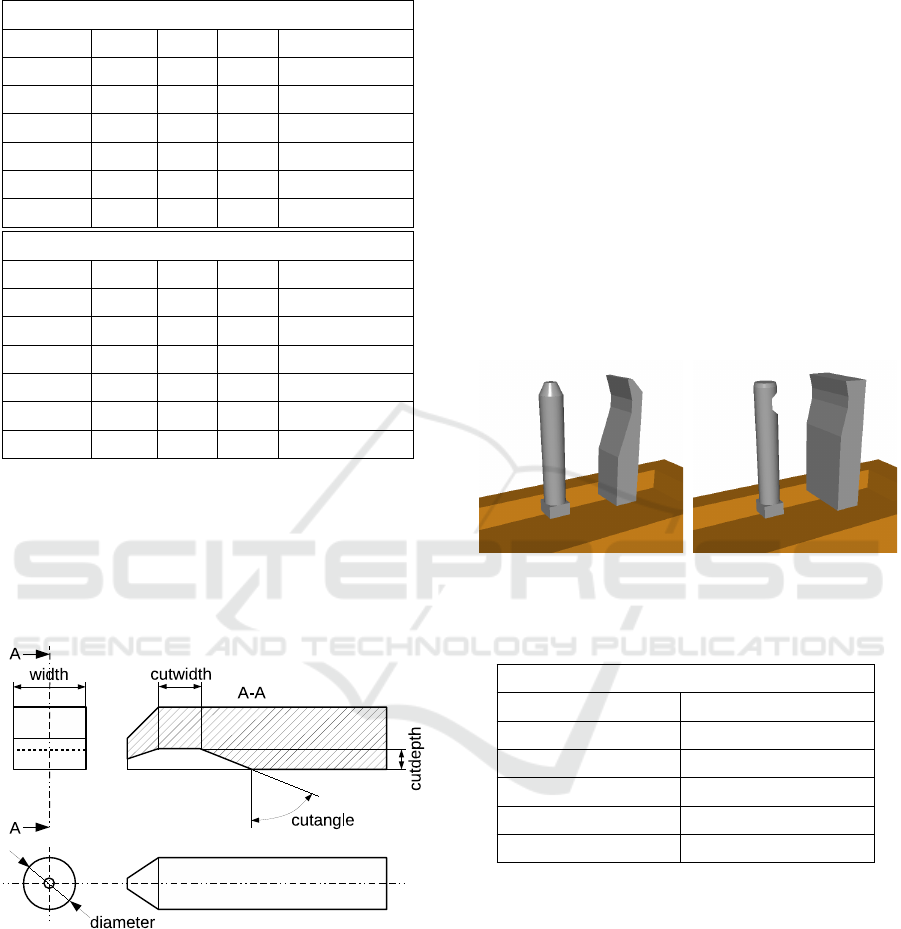
Table 1: The sampling defined for the individual offset axes
in alignment verification experiments.
Bracket scenario
Axis Min Step Max N. of samples
X [mm] -10 0.1 5 151
Y [mm] -10 0.1 10 201
Z [mm] -12.5 0.1 12.5 251
θ
x
[
◦
] -60 0.5 60 241
θ
y
[
◦
] -60 0.5 50 221
θ
z
[
◦
] -45 0.5 45 181
Heatshield scenario
Axis Min Step Max N. of samples
X [mm] -25 0.1 25 501
Y [mm] -15 0.1 15 301
Z [mm] -15 0.1 15 301
θ
x
[
◦
] -30 0.5 30 121
θ
y
[
◦
] -40 0.5 40 161
θ
z
[
◦
] -40 0.5 30 141
part of the bracket that is not in contact with the fin-
ger during grasping, the imprint can be constructed
successfully.
The chamfering of the bracket finger was prede-
termined for the PFO method. The gripper used a 20
mm stroke for the grasping of the bracket.
Figure 5: The brackets finger geometry parametrization.
The optimization was performed with the use
of Simplex optimization method (Nelder and Mead,
1965) starting from an arbitrarily chosen point in the
parameter space. The objective function selected was
defined as a geometric average of Gripper Quality in-
dices (see Equation 1) with the weights defined as:
w
S
= 1 w
R
= 0 w
C
= 0 w
A
= 1 (3)
w
W
= 0.1 w
T
= 0.01 w
V
= 0.01 (4)
The optimization process took 60 steps for the
PFO method. The computation time was 6.5 hours
for the PFO method and 7.5 hours for the IFM. The
optimization was done using an 8-core i7-4702MQ
CPU 2.20GHz machine with 8GB of RAM. The set-
up time of the workcell and definition of the task con-
text took about 30 minutes and is identical for both the
methods. The total set-up time for the PFO method
was 1-1.5 hours and 10-20 minutes for the IFM.
Figure 6 shows the fingers designed for the
bracket object grasping scenario using both the PFO
method and the IFM. The parameters of the PFO fin-
gers before and after optimization are gathered in Ta-
ble 2. The final score of the IFM fingers was found to
be Q : 0.533. In addition to providing the basic finger
shape, the user input consists of defining 6 parameters
for the PFO method.
(a) The PFO method. (b) The IFM.
Figure 6: Optimized finger for handling the bracket object.
Table 2: The bracket fingers optimized parameters.
PFO Q: 0.134 → 0.616
diameter width
10.00 → 8.53 [mm] 10.00 → 14.50 [mm]
cutwidth cutdepth
5.00 → 4.72 [mm] 5.00 → 5.42 [mm]
cutangle
45.00 → 71.51 [
◦
]
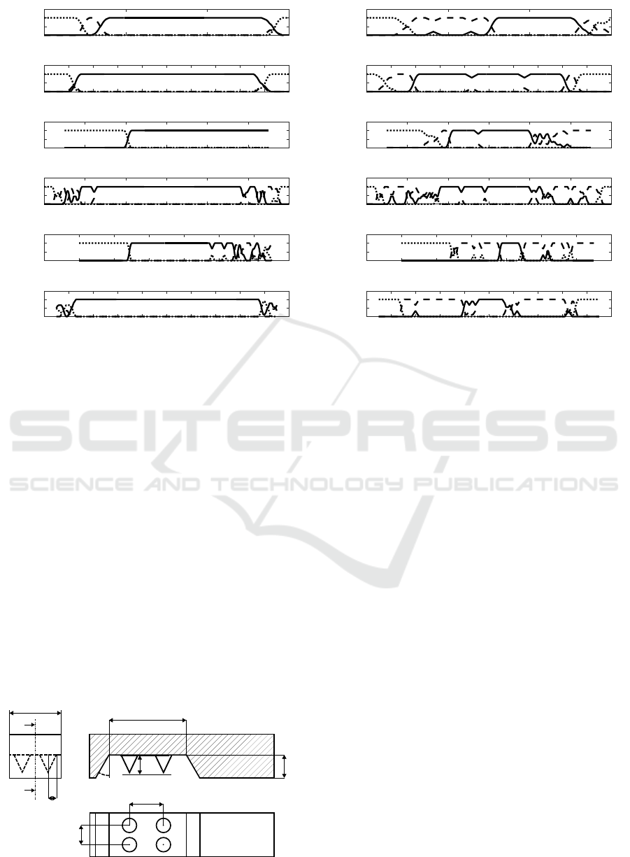
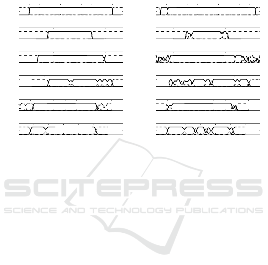
Figure 7 presents the results of grasping the
bracket object using fingers designed using PFO and
IFM methods for increasing offsets introduced in axes
defined in Section 4. It can be seen that the two meth-
ods failure regions are quite similar. However, the
success range of the IFM is smaller, along some of
the axis, than that of the PFO method. This is because
the object is able to rotate in the cut-out of the two fin-
gers and a large part of the result are hence classified
as misaligned.
The IFM method offers a great advantage in terms
of time and effort saving in the set-up phase. In
this scenario it does, however, results in lower per-
formance than that of the PFO method.
Designing Fingers in Simulation based on Imprints
309
offset [mm]
-10 -5 0 5
S/M/F
0
0.5
1
1.5
X offset (PFO)
offset [mm]
-10 -8 -6 -4 -2 0 2 4 6 8 10
S/M/F
0
0.5
1
1.5
Y offset (PFO)
offset [mm]
-15 -10 -5 0 5 10 15
S/M/F
0
0.5
1
1.5
Z offset (PFO)
offset [deg]
-60 -40 -20 0 20 40 60
S/M/F
0
0.5
1
1.5
RX offset (PFO)
offset [deg]
-80 -60 -40 -20 0 20 40 60
S/M/F
0
0.5
1
1.5
RY offset (PFO)
offset [deg]
-50 -40 -30 -20 -10 0 10 20 30 40 50
S/M/F
0
0.5
1
1.5
RZ offset (PFO)
offset [mm]
-10 -5 0 5
S/M/F
0
0.5
1
1.5
X offset (IFO)
offset [mm]
-10 -8 -6 -4 -2 0 2 4 6 8 10
S/M/F
0
0.5
1
1.5
Y offset (IFO)
offset [mm]
-15 -10 -5 0 5 10 15
S/M/F
0
0.5
1
1.5
Z offset (IFO)
offset [deg]
-60 -40 -20 0 20 40 60
S/M/F
0
0.5
1
1.5
RX offset (IFO)
offset [deg]
-80 -60 -40 -20 0 20 40 60
S/M/F
0
0.5
1
1.5
RY offset (IFO)
offset [deg]
-50 -40 -30 -20 -10 0 10 20 30 40 50
S/M/F
0
0.5
1
1.5
RZ offset (IFO)
Figure 7: The comparison of the alignment results in the bracket object scenario for the parametrized gripper (on the left) and
for the gripper designed using the imprint method (on the right). Solid line represents the grasp success rate, dotted line – the
misalignment rate, and the dashed line – the failure rate.
4.2 Heatshield Object Scenario
In the experiments performed for the heatshield sce-
nario, the gripper design optimization was performed
using the predefined gripper finger shapes (a set of
block fingers with dimensions 20 × 30 × 75 mm, wrt.
the coordinate system in Figure 4(b)) with cut-outs
designed using (a) the PFO method and (b) the IFM.
The parametrization scheme chosen for the heat-
shield object grasping fingers designed using the PFO
method is presented in Figure 8. The grasping fingers
for the IFM were designed with the heatshield as the
imprint object and the imprint pose (see Section 3.2)
was the nominal grasp pose seen in Figure 4(b).
The gripper used a 70 mm stroke for the grasping
of the heatshield. The PFO method has a predefined
cutdepth and cutwidth set to 15 and 30 mm respec-
cutwidth
width
radius
angle
cutdepth
dist
x
dist
y
height
A-A
A
A
Figure 8: The heatshield finger parametrization.
tively based on the heatshields actual size.
The finger optimization was performed with the
use of Simplex optimization method starting from a
point selected in the parameter space. The objective
function used was defined as a geometric average of
Gripper Quality indices (see Equation 1) with the fol-
lowing weights:
w
S
= 1 w
R
= 0 w
C
= 0 w
A
= 1 (5)
w
W
= 0.1 w
T
= 0.01 w
V
= 0.01 (6)
The optimization process took 53 steps for the
PFO method and 7.1 hours to computeand the IFM
took 16.7 hours of runtime in total The algorithms
were run on a Intel Core i7-3610QM CPU 2.30GHz
with 8GB of RAM, the program was run single
threaded. The total set-up time of the workcell and
task context took approximately 30 minutes. And the
time to design the fingers for the PFO method took
1-1.5 hour and less than 10 minutes for the IFM.
Figure 9 shows the comparison of the fingers de-
signed for the heatshield object grasping scenario us-
ing both the PFO method and the IFM. The param-
eters of the gripper before and after optimization are
presented in Table 3. The final score of the gripper
using the IFM was Q : 0.46. The user has to pro-
vide the basic finger shape for both of the methods.
Additionally, the required input consists of defining 6
parameters for the PFO method.
SIMULTECH 2017 - 7th International Conference on Simulation and Modeling Methodologies, Technologies and Applications
310
(a) The PFO method. (b) The IFM.
Figure 9: Optimized fingers for the heatshield object.
Table 3: The heatshield fingers optimized parameters.
PFO Q: 0 → 0.44
angle width
20.00 → 32.91 [deg] 30.00 → 29.99 [mm]
dist
x
dist
y
13.00 → 13.00 [mm] 13.00 → 15.81 [mm]
radius height
5.00 → 5.00 [mm] 5.00 → 5.01 [mm]
Figure 10 presents the results of grasping the heat-
shield object using fingers designed using PFO and
IFM methods for increasing offsets introduced in axes
defined in Section 4. Both the fingers found offer a
similar level of performance. The IFM has on aver-
age a larger number of successful grasps along the six
axis, but overall similar performance is obtained. The
PFO method clearly has the advantage of obtaining
its result faster than the IFM, since less than half the
simulation time is needed. However, using the IFM
does offers an advantage in terms of time and effort
saving in the set-up phase.
5 DISCUSSION
In Section 4 the experiments in simulation where pre-
sented aimed at comparing the quality of grippers pro-
duced using both methods in terms of the grasping
alignment capabilities achieved. The alignment capa-
bility of a gripper was quantified as a measure of the
degree at which it can compensate for grasping pose
uncertainty, while still achieving the predictable pose
of the grasped object wrt. the gripper.
The averaged results for both position and angle
offsets is presented in Table 4. The linear and an-
gular offsets are grouped together in the table, and
the total percentage of the grasp outcomes is shown
as well. Overall, the results are comparable for both
methods grasping the heatshield, see Section 4.2, with
the IFM performing a little better than the PFO. How-
ever, the results for the bracket are largely different.
With almost twice the success of the IFM, the PFO
method shows a significant advantage. This is due
to the unforeseen objects interaction with the cut-out
shape that allows for rotation along θ
y
in the grasp of
the IFM gripper, and the gripper performance hence
drastically falls during the tests.
It is also worth noting that the gripper designed
for the bracket using the PFO method grasps the ob-
ject at a different pose wrt. the TCP than that designed
using the IFM. This is because the PFO gripper was
parametrized with a cut-out located only on the exte-
rior grasping finger, while the IFM generates a cut-out
in both fingers. The choice of when to apply a cut-out
to a finger is an option that can be explored in further
IFM research.
Table 4: The averaged grasp experiment results for the PFO
and IFM methods used in the bracket and the heatshield sce-
narios. The columns indicate: S – the successful grasp rate,
M – the misaligned grasp rate and F – the failure grasp rate.
PFO IFM
bracket object
%S %M %F %S %M %F
Pos. 71.5 3.5 25.0 48.5 29.0 22.5
Ang. 75.0 9.0 16.0 28.3 50.3 21.4
Total 73.3 6.3 20.5 38.4 39.7 22.0
heatshield object
%S %M %F %S %M %F
Pos. 62.0 31.3 6.7 69.7 27.0 3.3
Ang. 68.7 7.7 23.7 69.0 13.7 17.3
Total 65.4 19.5 15.2 69.4 20.4 10.3
6 CONCLUSION
In this paper a new method to generate optimized fin-
ger cut-outs was presented (IFM). The method uses
the idea of using the imprint to produce the finger ge-
ometry. Furthermore the method introduces a profile
surrounding the cut-out.
The IFM was compared to a previously devel-
oped method (PFO) in terms of set-up and run time
and grasping experiments performed in simulations.
Compared to PFO, the IFM design method proved to
require considerably less set-up time, on average 15
minutes compared to 1-1.5 hours for the PFO. This is
offset by a longer computation time (on average 12.1
hours using IFM and 6.8 hours for the PFO method).
This is however not an important factor, considering
that the reduction in required man-hours greatly out-
weighs the increase in cheap computational power.
Designing Fingers in Simulation based on Imprints
311
offset [mm]
-25 -20 -15 -10 -5 0 5 10 15 20 25
S/M/F
0
0.5
1
1.5
X offset (PFO)
offset [mm]
-15 -10 -5 0 5 10 15
S/M/F
0
0.5
1
1.5
Y offset (PFO)
offset [mm]
-15 -10 -5 0 5 10 15
S/M/F
0
0.5
1
1.5
Z offset (PFO)
offset [deg]
-50 -40 -30 -20 -10 0 10 20 30
S/M/F
0
0.5
1
1.5
RX offset (PFO)
offset [deg]
-40 -30 -20 -10 0 10 20 30 40 50
S/M/F
0
0.5
1
1.5
RY offset (PFO)
offset [deg]
-30 -20 -10 0 10 20 30 40
S/M/F
0
0.5
1
1.5
RZ offset (PFO)
offset [mm]
-25 -20 -15 -10 -5 0 5 10 15 20 25
S/M/F
0
0.5
1
1.5
X offset (IFO)
offset [mm]
-15 -10 -5 0 5 10 15
S/M/F
0
0.5
1
1.5
Y offset (IFO)
offset [mm]
-15 -10 -5 0 5 10 15
S/M/F
0
0.5
1
1.5
Z offset (IFO)
offset [deg]
-50 -40 -30 -20 -10 0 10 20 30
S/M/F
0
0.5
1
1.5
RX offset (IFO)
offset [deg]
-40 -30 -20 -10 0 10 20 30 40 50
S/M/F
0
0.5
1
1.5
RY offset (IFO)
offset [deg]
-30 -20 -10 0 10 20 30 40
S/M/F
0
0.5
1
1.5
RZ offset (IFO)
Figure 10: The comparison of the alignment results in the heatshield object scenario for the PFO gripper (on the left) and for
the gripper designed using the IFM (on the right). Solid line represents the grasp success rate, dotted line – the misalignment
rate, and the dashed line – the failure rate.
The IFM requires far less manual user input, par-
ticularly in cases (such as heatshield), where it is dif-
ficult to conceive a parametrization scheme that suits
the grasping of a complicated geometrical shape. The
propose IFM therefore simplifies the gripper design
proses significantly. Even in the case of the sim-
pler objects (such as bracket), it is of great advan-
tage to have the grasping profile generated automat-
ically. The bracket object provides a challenge for the
IFM, since due to the necessity of using an internal
grasp. The general dimensions and external features
of the internal grasping finger (which is not generated
through imprinting) are of high importance in cases
like these.
Additionally, the IFM seems to produce cut-out
profiles which more closely resemble the geometry of
the object. This in turn allows for more robustness in
the grasps performed, due to larger contact surfaces.
This is also important in terms of the reduction of the
forces exerted on the objects, which is of importance
in the tasks of handling fragile and flexible materials.
It can be concluded, that using both of these meth-
ods in conjunction would utilize their synergy: the
PFO method is best suited for the choice and opti-
mization of the external finger profile (e.g. with the
parametrization chosen from a pre-defined library of
finger shapes), while the IFM is used to facilitate the
parametrization of the cut-out.
ACKNOWLEDGEMENTS
This work has received funding from the EU project
ReconCell (ICT Innovation for Manufacturing SMEs
(I4MS), project number 680431).
REFERENCES
Berenson, D., Diankov, R., Nishiwaki, K., Kagami, S., and
Kuffner, J. (2007). Grasp planning in complex scenes.
In Humanoid Robots, 2007 7th IEEE-RAS Interna-
tional Conference on, pages 42–48.
Blanes, C., Mellado, M., Ortiz, C., and Valera, A. (2011).
Review. technologies for robot grippers in pick and
place operations for fresh fruits and vegetables. Span-
ish Journal of Agricultural Research, 9(4):1130–
1141.
Borst, C., Fischer, M., and Hirzinger, G. (2004). Grasp
planning: How to choose a suitable task wrench space.
volume 1, pages 319–325.
Boubekri, N. and Chakraborty, P. (2002). Robotic grasping:
gripper designs, control methods and grasp configura-
tions – a review of research. Integrated Manufacturing
Systems, 13(7):520–531.
Causey, G. (2003). Guidelines for the design of robotic grip-
ping systems. Assembly Automation, 23(1):18–28.
Causey, G. C. and Quinn, R. D. (1998). Gripper design
guidelines for modular manufacturing. In Robotics
SIMULTECH 2017 - 7th International Conference on Simulation and Modeling Methodologies, Technologies and Applications
312

and Automation, 1998. Proceedings. 1998 IEEE Inter-
national Conference on, volume 2, page 1453–1458.
IEEE.
Ceccarelli, M., Cuadrado, J., and Dopico, D. (2002). An
optimum synthesis for gripping mechanisms by using
natural coordinates. Proceedings of the Institution of
Mechanical Engineers, Part C: Journal of Mechanical
Engineering Science, 216(6):643–653.
Cuadrado, J., Naya, M. A., Ceccarelli, M., and Carbone, G.
(2002a). An optimum design procedure for two-finger
grippers: a case of study. IFToMM Electronic Journal
of Computational Kinematics, 15403(1):2002.
Cuadrado, J., Naya, M. A., Ceccarelli, M., and Carbone, G.
(2002b). An optimum design procedure for two-finger
grippers: a case of study. IFToMM Electronic Journal
of Computational Kinematics, 15403(1):2002.
Ellekilde, L.-P. and Jørgensen, J. A. (2010). Robwork: A
flexible toolbox for robotics research and education.
Robotics (ISR), 2010 41st International Symposium
on and 2010 6th German Conference on Robotics
(ROBOTIK), pages 1 –7.
Ellekilde, L. P. and Petersen, H. G. (2006). Design and test
of object aligning grippers for industrial applications.
In 2006 IEEE/RSJ International Conference on Intel-
ligent Robots and Systems, pages 5165–5170.
Ferrari, C. and Canny, J. (1992). Planning optimal grasps.
pages 2290–2295.
Honarpardaz, M., Tarkian, M.,
¨
Olvander, J., and Feng, X.
(2017). Finger design automation for industrial robot
grippers: A review. Robotics and Autonomous Sys-
tems, 87:104 – 119.
Jørgensen, J. A., Ellekilde, L.-P., and Petersen, H. G.
(2010). RobWorkSim - an Open Simulator for Sensor
based Grasping - Conference papers - VDE Publish-
ing House. In ISR/ROBOTIK 2010 - ISR 2010 (41st
International Symposium on Robotics) and ROBOTIK
2010 (6th German Conference on Robotics). VDE-
Verlag.
Jørgensen, J. A. and Petersen, H. G. (2010). Grasp Syn-
thesis for Dextrous Hands Optimised for Tactile Ma-
nipulation. In Proceedings for the joint conference of
ISR 2010 (41st Internationel Symposium on Robotics)
und ROBOTIK 2010 (6th German Conference on
Robotics). VDE-Verlag.
Kintel, M. (2009). Openscad.
Kolluru, R., Valavanis, K., Smith, S., and Tsourveloudis,
N. (2000). Design fundamentals of a reconfigurable
robotic gripper system. Systems, Man and Cybernet-
ics, Part A: Systems and Humans, IEEE Transactions
on, 30(2):181–187.
Kraft, D., Ellekilde, L.-P., and Rytz, J. A. (2012). Au-
tomized grasp generation and improvement for indus-
trial bin-picking. Robotics and Computer Integrated
Manufacturing. (to be submitted).
Krenich, S. (2014). Optimal design of robot gripper mecha-
nism using force and displacement transmission ratio.
Applied Mechanics and Materials, 613:117–125.
Lanni, C. and Ceccarelli, M. (2009). An optimization prob-
lem algorithm for kinematic design of mechanisms for
two-finger grippers. Open Mechanical Engineering
Journal, 3:49–62.
Li, Y., Fu, J., and Pollard, N. (2007). Data driven grasp
synthesis using shape matching and task-based prun-
ing. IEEE Transactions on Visualization and Com-
puter Graphics, 13.
Nelder, J. A. and Mead, R. (1965). A simplex method
for function minimization. The Computer Journal,
7(4):308–313.
Schunk (2015). Schunk egrip.
Schuster, A., Becker, R., and Poguntke, M. (2014). Method
for the production of customer-specific components.
UWO2014060605 A1.
Smith, R. (2008). Open dynamics engine.
http://www.ode.org/.
Stulp, F., Theodorou, E., Buchli, J., and Schaal, S. (2011).
Learning to grasp under uncertainty. In IEEE In-
ternational Conference on Robotics and Automation
(ICRA), pages 5703–5708.
Thulesen, T. N. and Petersen, H. G. (2016). RobWork-
PhysicsEngine: A new dynamic simulation engine for
manipulation actions. In 2016 IEEE International
Conference on Robotics and Automation (ICRA).
Velasco, V. B. and Newman, W. S. (1998). Computer-
assisted gripper and fixture customization using rapid-
prototyping technology. In Proceedings. 1998 IEEE
International Conference on Robotics and Automation
(Cat. No.98CH36146), volume 4, pages 3658–3664
vol.4.
Wolniakowski, A., Jorgensen, J. A., Miatliuk, K.,
Gosiewski, Z., Petersen, H. G., and Kr
¨
uger, N. (2017).
Task and context sensitive gripper design learning us-
ing dynamic grasp simulation. Journal of Intelligent
and Robotic Systems. (in print).
Wolniakowski, A., Jorgensen, J. A., Miatliuk, K., Petersen,
H. G., and Kr
¨
uger, N. (2015). Task and context sen-
sitive optimization of gripper design using dynamic
grasp simulation. In Methods and Models in Automa-
tion and Robotics (MMAR), 2015 20th International
Conference on, pages 29–34.
Wolniakowski, A., Kramberger, A., Gams, A., Chrysosto-
mou, D., Hagelskjaer, F., Thulesen, T. N., Kiforenko,
L., Buch, A. G., Bodenhagen, L., Petersen, H. G.,
Madsen, O., Ude, A., and Kr
¨
uger, N. (2016). Opti-
mizing grippers for compensating pose uncertainties
by dynamic simulation. In IEEE/RSJ Int. Conf. on In-
telligent Robots and Systems (IROS). submitted.
Wolniakowski, A., Miatliuk, K., Kr
¨
uger, N., and Rytz, J. A.
(2014). Automatic evaluation of task-focused paral-
lel jaw gripper design. In International Conference
on Simulation, Modeling, and Programming for Au-
tonomous Robots.
Zhang, M. T. and Goldberg, K. (2006). Designing robot
grippers: optimal edge contacts for part alignment.
Robotica, 25(03):341.
Designing Fingers in Simulation based on Imprints
313
