
Dynamic Programming Resolution and Database Knowledge for Online
Predictive Energy Management of Hybrid Vehicles
Rustem Abdrakhmanov and Lounis Adouane
Institut Pascal/IMobS3, UCA/SIGMA - UMR CNRS 6602, Clermont-Ferrand, France
Keywords:
Hybrid Electric Vehicle, Energy Management Strategy, Dynamic Programming, Online Sub-optimal Opti-
mization, SOC Prediction, Multi-dimensional Database Knowledge.
Abstract:
This paper presents a sub-optimal strategy, based on Dynamic Programming (DP) approach, for online energy
(electric battery and fuel) optimization of a Hybrid Electric Vehicle (HEV). An optimal offline optimization is
first proposed in this work, permitting to have simultaneous speed profile optimization and optimal power split
strategy of a series-parallel hybrid bus. The aim of this optimization is mainly to reduce the fuel and electrical
energy consumption of the studied HEV while maintaining smooth bus navigation to ensure the passengers’
comfort. It is assumed in this first proposal that current road profile (slope, geometry, etc.) and the overall
bus trip (time at the stations) are known in advance. Afterward, the basis of the offline optimal strategy has
been adapted in order to deal online with the current road profile and driver velocity demand. The proposed
sub-optimal online strategy uses mainly an appropriate speed profile and power-split database, obtained offline
with DP, in order to cope with the current bus situations, and this is carried out by using a multi-dimensional
interpolation method. The present work is conducted on a dedicated high-fidelity model of the hybrid bus that
was developed on MATLAB/TruckMaker software.
1 INTRODUCTION
The problem of reducing the environment pollution in
order to save the planet became one of the most im-
portant challenges in the world. Besides, the world-
wide crisis of the fossil fuel resources, which dimin-
ish at high rate, aggravates it. These two global as-
pects made the big industrial companies and the state
governments invest increasingly into the alternative
energy sources. The hybrid electric vehicles (HEV)
promise a relevant solution with regard to the objec-
tives of reducing the fuel consumption, as well as
the decrease of the exhaust gazes emission (Murphey,
2008).
Concerning the energy optimization in the HEV
and pure electric vehicles (EV), the researches mainly
deal with two kind of problems: 1) energy power
management for a given velocity profile (Rousseau,
2008) (Chen et al., 2014) (Kitayama et al., 2015);
2) velocity profile optimization for EV or conven-
tional vehicles (Ozatay et al., 2014) (Tokekar et al.,
2014) (Dib et al., 2014). The application of the
optimal control theory to power management on
HEV has been the most popular approach, which in-
cludes linear programming, optimal control and espe-
cially Dynamic Programming (DP) (Rousseau, 2008)
(Chen et al., 2014) (Pei and Leamy, 2013) (Song
et al., 2015)(Kamal et al., 2017) (Abdrakhmanov and
Adouane, 2017). These techniques have been widely
studied and applied to a broad range of vehicles.
The authors in (Pei and Leamy, 2013) propose
an approach for determining the State Of the Charge
(SOC)-dependent equivalent cost factor in HEV su-
pervisory control problems using DP. (Song et al.,
2015) use the DP approach to deal with the global op-
timization problem for deriving the best configuration
for the drivetrain components sizes and energy split
strategies of a hybrid energy storage system, includ-
ing a battery and a supercapacitor, for an electric city
bus. (Zhang et al., 2014) proposed a DP-rule based
(DP-RB) algorithm to solve the global energy opti-
mization problem in a real time controller of a plug-
in hybrid electric bus (PHEB). A control grid (a set of
deterministic rules) is built for a typical city route ac-
cording to the station locations and discrete SOC lev-
els. An offline DP with historical running information
of the driving cycle is used to deduce optimal control
parameters of RB on all points of the control grid. For
a RB control strategy, control parameters are selected
according to the current position and battery SOC of
132
Abdrakhmanov, R. and Adouane, L.
Dynamic Programming Resolution and Database Knowledge for Online Predictive Energy Management of Hybrid Vehicles.
DOI: 10.5220/0006437301320143
In Proceedings of the 14th International Conference on Informatics in Control, Automation and Robotics (ICINCO 2017) - Volume 1, pages 132-143
ISBN: 978-989-758-263-9
Copyright © 2017 by SCITEPRESS – Science and Technology Publications, Lda. All rights reserved

PHEB. The trajectory is divided into N segments and
the control parameters between station st
n
and station
st
n+1
are selected as a Rule
n
, which is determined by
the SOC S
n
at station st
n
.
Other authors as (Tokekar et al., 2014) studied
the problem of the velocity profiles search for a car-
like robots in order to minimize the energy consumed
while traveling along a given path, whereas (Dib et al.,
2014) tackle an energy management problem for an
electric vehicle compliant with online requirements
for “eco-driving application”. The main difference
between two last papers cited above is that the robot
is fully autonomous, and the electric vehicle is con-
trolled by a driver, but the driver receives the velocity
profile proposed by an eco-driving system. (Ozatay
et al., 2014) propose an optimization of the speed tra-
jectory to minimize the fuel consumption and com-
municate it to the driver. In their approach the driver
sends the information of the intended travel destina-
tion to the server. The server generates a route, col-
lects the associated traffic and geographical informa-
tion, and solves the optimization problem by a spa-
tial domain DP algorithm that utilizes accurate vehi-
cle and fuel consumption models to determine the op-
timal speed trajectory along the route. (Kim et al.,
2009) use model predictive control for the velocity
and power split optimization in HEVs. A given ve-
locity profile is optimized by setting the constraints on
the velocity and the acceleration of the vehicle. This
allows to smooth the current velocity profile without
generating a new one. The authors (Van Keulen et al.,
2010a) proposed a method that solves the velocity op-
timization problem for HEVs, based upon informa-
tion from Global Navigation Satellite-based Systems,
assuming that the velocity trajectory has a predefined
shape. Although this method is used for HEVs, the
authors do not deal with the energy management op-
timization aspect. An optimal control problem was
proposed to determine the potential of a HEV opera-
tional strategy controlling gear shift, torque split, and
velocity at the same time (Heppeler et al., 2014). It
is proposed in this paper a discrete dynamic program-
ming approach to find a global optimal solution for
fuel efficiency potential analysis, optimizing torque
split, gear shifting and velocity trajectory.
In their latter works (Heppeler et al., 2016), as
well as (Shen et al., 2015) and (Sun et al., 2015), deal
with the problem of prediction of the battery SOC.
These articles use the offline global optimal control
to generate the desired SOC trajectory, later this val-
ues are used as an input in Model Predictive Control
(MPC). It is proved that prediction of the future tra-
jectories, based upon either past or predicted vehicle
velocity and road grade trajectories, could help in ob-
taining a solution close to the optimal (Van Keulen
et al., 2010b).
Unlike the previous publications, the present pa-
per proposes an optimal offline optimization based
on DP permitting to have simultaneous speed pro-
file optimization and optimal power split strategy of
a series-parallel hybrid bus, aiming to reduce the fuel
and electrical energy consumption. For an urban bus
the route is normally known in advance, so the opti-
mization is performed for given road profile. One of
the most important aspects of the public transporta-
tion is the passengers comfort. For that purpose the
maximal permitted acceleration and deceleration are
taken into account. As the hybrid bus’ electric mo-
tor and engine have different dynamic characteristics
(the power supplied, the response time, etc.), the dy-
namic constraints linked to the dynamic motors are
taken into account. An online sub-optimal speed pro-
file and related power split generation using a multi-
dimensional interpolation is developed to deal online
with the current road profile and driver velocity de-
mand. This is carried out using the Optimal Profile
Database based on DP (OPD-DP). The battery SOC
is estimated and predicted, using Kalman Filter esti-
mation, in order to guarantee that at the end of op-
erational cycle (in the end of a course of a day) the
electric battery charge is not below its permitted min-
imum level.
The rest of the paper is organized as follows. In
section 2, the studied bus powertrain and its dynami-
cal model are presented. Section 3 presents the pro-
posed offline DP algorithm and its constraint set. Sec-
tion 4 describes DP modeling of offline strategy, as
well as the use of the obtained results for online im-
plementation of the sub-optimal strategy and SOC
prediction. In section 5, several simulation results
are presented showing the efficiency of the proposed
velocity profile optimization and energy management
strategies. Finally, conclusions and some prospects
are given in the last section.
2 MODELING OF THE HYBRID
BUS
The aim of this section is to illustrate the architecture
and the mathematical model of the studied system,
i.e., BUSINOVA hybrid bus, developed by SAFRA
company (cf. Figure 1)
1
. This bus is composed of an
electric motor, a hydraulic motor, an internal combus-
tion engine and battery as the propulsion powertrain
system of the vehicle.
1
http://www.businova.com
Dynamic Programming Resolution and Database Knowledge for Online Predictive Energy Management of Hybrid Vehicles
133
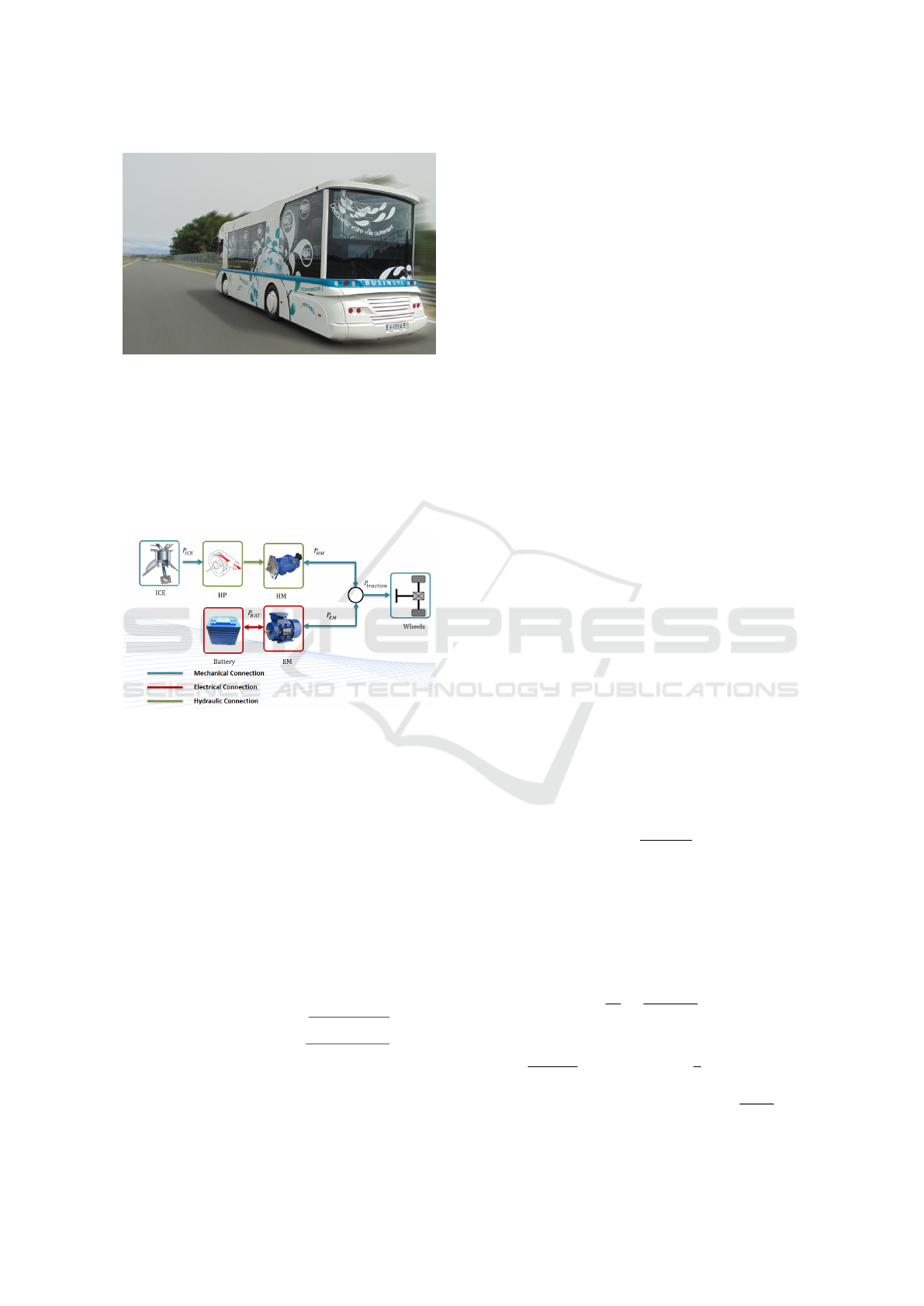
Figure 1: BUSINOVA hybrid bus.
2.1 Hybrid Bus Powertrain
Architecture
The model of the studied hybrid bus is based
on a series-parallel power-split hybrid architecture
(Bayindir et al., 2011). A simple block diagram of
the power flows in the bus is shown in Figure 2.
Figure 2: Block diagram of the powertrain power flows.
(ICE: internal combustion engine, HP: hydraulic pump,
HM: Hydraulic motor, EM: electric motor).
The electric (EM) and hydraulic (HM) motors are
both directly connected to the transmission and can
ensure simultaneously or independently the traction
of the bus. On the other hand, the internal combustion
engine (ICE) is coupled to a hydraulic pump (HP) for
driving the HM, and therefore allowing the ICE load
shifting.
The rotational speeds of the HM and the EM are
imposed by the wheels speed in proportion to the re-
duction ratios of HM and EM respectively. Moreover,
the rotational speed ω
HM
and the torque T
HM
are ex-
pressed as follows:
ω
HM
(T
ICE
,D
HM
) =
D
HP
.η
v
HM
.ω
ICE
D
HM
.η
v
HP
T
HM
(T
ICE
,D
HM
) =
D
HM
.η
m
HM
.T
ICE
D
HP
.η
m
HP
(1)
where ω
ICE
, T
ICE
are respectively rotational speed
and torque of the ICE, and D
HM
, D
HP
, η
m
HM
, η
m
HP
,
η
v
HM
, η
v
HP
are respectively displacement, mechanical
efficiency and volumetric efficiency of the HM and
the HP.
The BUSINOVA can operate according to the
modes described below:
1. the propulsion is fully supplied by the electric mo-
tor (mode I),
2. the bus is actuated by the hydraulic motor via the
ICE (mode II),
3. the mode III implies the hybrid operation of the
EM and the HM via ICE,
4. the regenerative braking (mode IV) - the part of
the kinetic energy during braking phase is recu-
perated to charge the electric battery.
2.2 Dynamical Model
This part is dedicated to the dynamical equations de-
scribing the bus. The purpose of the dynamical model
is to have a realistic global behavior of the bus in or-
der to validate the proposed energy management tech-
niques. To describe it in a generic manner, assume
that the bus is moving up the slope of θ degree (cf.
Figure 3). The origin of the coordinates is situated in
the Center of Mass (CoM). It is supposed that CoM
of the bus is in its geometric center. The dynamical
equation of the bus is given as follows:
~
F
tr
+
~
F
rr
+
~
F
ad
+
~
F
g
+
~
F
brake
= (M + M
eq
)~a (2)
where
~
F
tr
traction force,
~
F
rr
rolling resistance,
~
F
ad
aerodynamic force,
~
F
g
gravity force,
~
F
brake
mechan-
ical brake force, M bus weight, M
eq
equivalent mass
of rotating parts, ~a bus acceleration.
To produce the bus acceleration, it is necessary to
take into account the moments of inertia of the rotat-
ing components (e.g., rotor of the EM, crankshaft of
the ICE, driving axle, etc.). It is done by introducing
the equivalent mass M
eq
of the rotating components:
M
eq
=
i
g
η
pt
J
rot
r
2
(3)
where i
g
gear ratio, η
pt
powertrain efficiency, J
rot
total
inertia of the rotating components in the transmission,
and r the wheel radius (Cheng et al., 2007).
The traction force F
tr
is linked to the torque pro-
duced by the powertrain T
pt
via gear ratio i
g
, power-
train efficiency η
pt
. Expanding the dynamical equa-
tion (2), the following relation is obtained:
a =
dv
dt
=
1
M + M
eq
H (4)
with
H =
i
g
η
pt
T
pt
r
− µ
rr
F
N
sign(v) −
1
2
ρAC
d
(v + v
wind
)
2
− Mg sin(θ) −
T
brake
r
(5)
ICINCO 2017 - 14th International Conference on Informatics in Control, Automation and Robotics
134

where:
• T
pt
: output powertrain torque from the gearbox,
• µ
rr
: rolling resistance coefficient, F
N
= Mgcos(θ)
normal force, g gravity acceleration, θ slope an-
gle, v bus speed,
• ρ: the air density, A the frontal area of the bus, C
d
drag coefficient, v
wind
wind speed,
• T
brake
: the brake torque provided by the bus me-
chanical brake system.
Figure 3: Forces acting on the bus.
3 OVERALL MULTI-CRITERIA
OPTIMIZATION
FORMULATION
The objective of the optimal control problem is to find
the optimal bus velocity profile and energy split be-
tween the actuators for a given trajectory D. The opti-
mization is performed in the spatial domain by means
of the following transformation (conversion from time
domain into spatial domain) (Ozatay et al., 2014):
a =
dv
dt
=
dv
dD
dD
dt
=
dv
dD
v (6)
In that case the dynamics of the BUSINOVA given
in equation (4) could be re-written with the following
equation:
dv
dD
=
1
(M + M
eq
)v
H (7)
As any problem of optimization, it is important to
define optimization criteria. In our case, the criteria is
defined in order to optimize the fuel mass consumed
˙m
f uel
(Zeng, 2009) and the electric power P
EM
con-
sumed by the electric motor during the trip D:
J
D
= αJ
1
+ (1 − α)J
2
+ βJ
3
(8)
where:
J
1
=
Z
D
f
0
˙m
f uel
(P
ICE
(D),P
HM
(D),D
HM
)
v(D)
dD
(9)
with ˙m
f uel
fuel mass consumed is a function of
ICE power P
ICE
, as well as of HM power P
HM
and HM displacement D
HM
(Zeng, 2009);
J
2
=
Z
D
f
0
P
EM
(D)
v(D)
dD (10)
with P
EM
(D) EM power.
J
3
=
Z
D
f
0
|a|
v(D)
dD (11)
which is introduced to avoid abrupt velocity
changes and make the speed profile smoother with
a vehicle acceleration,
D
f
is the total traveled distance;
v the bus speed;
α is a constant weight coefficient such as α ∈ [0 1]
and β is a scale factor.
In order to have adequate results, each part of the cost
function (8) is normalized. The fuel consumption rate
˙m
f uel
is transformed into equivalent consumed engine
power P
engine
:
P
engine
= ˙m
f uel
Q
LHV
(12)
where Q
LHV
is lower heating value of a used fuel. For
diesel Q
LHV
= 43MJ/kg.
The minimization of the cost function (8) is the
subject to the bus dynamical model (7), as well as to
the constraints imposed on the control input and state
during the performed optimization.
3.1 Boundary Conditions
To set the boundary conditions for optimization pro-
cedure, we take into consideration a normal operation
for an urban bus, traveling from one stop to another
with the appropriate velocity profile v(D) (cf. Figure
4), which should be obtained according to the pro-
posed optimization algorithm based on DP (cf. sec-
tion 4).
To simplify the notation, initial v(0) and final
v(D
f
) speeds are called v
0
and v
f
. Generally for the
developed DP-based algorithm (cf. section 4), they
Figure 4: An example of a bus trip from one bus stop to
another.
Dynamic Programming Resolution and Database Knowledge for Online Predictive Energy Management of Hybrid Vehicles
135

can have any non-negative value. But in practice, the
bus trip to run from one bus stop to another implies
that:
v
0
= v
f
= 0 (13)
The trip duration T to arrive to the next bus stop is im-
posed by the schedule that must be respected. As the
optimization is computed with floating-point num-
bers, a constant τ is introduced (cf. equation (14)) to
calculate the range of the permitted final time t
f
flex-
ibility. But introduction of τ is also justified in real
systems, as the trip duration T cannot be absolutely
precise during the trip from D
0
to D
f
due to the traffic
jams, traffic lights, pedestrian crossing, etc.
t
f
= t
0
+ (1 ± τ)T (14)
where T is the pre-set trip duration, t
0
is the initial
time, τ is a very small value (τ → 0).
4 OFFLINE AND ONLINE
OPTIMIZATION STRATEGIES
BASED ON DP ALGORITHMS
This section is dedicated to the development of a
simultaneous speed profile optimization and an en-
ergy management strategy in offline and online mode.
The procedure of the decision tree construction is de-
scribed in details in section 4.1. The developed of-
fline algorithm permits to move to the online imple-
mentation by means of the Optimal Profiles Database
(cf. section ??), which generates the speed profile
and its energy management strategy, depending on the
road profile, the bus current bus state and velocity set-
point. The battery SOC estimation and prediction pro-
cedure is described in section 4.1.2.
4.1 Offline Optimization Strategy
DP Formulation
The optimization method used to solve the given op-
timal control problem is based on DP (Bellman and
Dreyfus, 2015) (Bertsekas, 1995), which provides the
global optimal solution over a given trip. The algo-
rithm proceeds from 0 to K steps in order to minimize
the following cost function:
J
k
(v
k
) = min
u
k
∈U
D
g
k
(v
k
,u
k
,∆D
k
) + J
k−1
( f (v
k
,u
k
))
(15)
where
• J
k
(v
k
) is the cost-to-go function from step 0 to
step K starting from v
0
with initial cost J
0
(v
0
) =
g
0
(v
0
) = 0;
• g
k
(v
k
,u
k
,∆D
k
) is the cost-to-go from state i to
state j.
• J
k−1
( f (v
k
,u
k
)) is the total cost starting from the
initial state to the state i.
• u
k
∈ U
D
is the control input determining the ve-
locity to go from the state i to the next state j.
The given optimization is aimed to solve two main
problems simultaneously: (i) Find the optimal speed
profile from D
0
to D
f
in time t
f
, minimizing the elec-
tric energy and fuel consumption; (ii) find the optimal
power split strategy to the speed profile in order to
provide the optimal functioning mode (cf. section 2)
and the percentage of the contribution of each motor
(EM and HM) in order to move the hybrid bus.
The paragraphs below detail the resolution of the
nonlinear optimization control problem formulated in
the spatial domain by using DP algorithm. A set of
points defines the route. Namely, the route consists
of the points P = [p
0
, p
1
, p
2
, ..., p
K
]. Every
point p
k
∈ P for k = 0,1, 2,...,K has its own charac-
teristics: p
k
= [x
k
,y
k
,θ
k
], where x
k
longitudinal po-
sition, y
k
lateral position, θ
k
road slope angle. The
given route of the length D is divided into K segments
of the sample length ∆D. Depending on the accelera-
tion/deceleration limits and on the ∆D segment length
(cf. Figure 4), the velocity v(D
k
) for a given segment
D
k
can increase or decrease with a fixed step ∆v. The
maximum number of ∆v is equal to 2N
v
+ 1:
V = {−N
v
∆v, ..., 0, ∆v, .. ., N
v
∆v} (16)
where N
v
∈ N.
DP-SEO Algorithm Flowchart
Figure 5 shows the proposed DP based Speed and
Energy Optimization (DP-SEO) algorithm. The pro-
posed DP-SEO has the following main steps.
Action 1. It initializes the road profile P, dis-
tance discretization step ∆D (cf. Figure 4), K num-
ber of ∆D, a set of maximum permissible values of
speed increment ∆v. To perform a simultaneous bus
speed profile and its power split optimization, the spe-
cific vector Λ = {0, 0.1,0.2,... ,1} is assigned with
Card(Λ) = m cardinal number of the set Λ, which
corresponds to the contribution of the EM and HM in
traction. Each state ν
j
≡ [P
k
,v
j
,t
j
,Parent(v
j
)], with
v
j
speed, t
j
time, Parent(v
j
) previous state.
Action 2. It attributes an acceleration ∆v.
Action 3. It calculates the required torque T
set point
.
Decision 1. If T
set point
is negative, the braking is
applied (cf. Action 7).
Decision 2. If T
set point
less than the maximum
torque that can be produced by EM and HM, then go
Action 4.
ICINCO 2017 - 14th International Conference on Informatics in Control, Automation and Robotics
136

Figure 5: Block diagram of the Dynamic Programming
based Speed and Energy Optimization (DP-SEO).
Action 4. It calculates the possible torque ratio
combinations according to Λ.
Decision 3. The EM and the engine, which drives
the HM, have different dynamic characteristics. EM
is capable of delivering a high starting torque. Unlike
EM, engine cannot provide torque at zero speed and
it produces maximum power at a certain speed (Pisu
and Rizzoni, 2007). The efficiency of the engine is
very much dependent on the operating point in the en-
gine’s performance map. Thus, to go from one state
to another not all the ∆T are feasible. To take this
constraint into account, the maximum values ∆T
EM
max
and ∆T
HM
max
are introduced. If the demanded torque
is higher that these values, then the development of
the decision tree in that direction is stopped. Other-
wise, go to Action 5.
Action 5. For the feasible combinations the cost-
to-go function g
k
(v
k
,u
k
,∆D
k
) is calculated (cf. equa-
tion (15)).
Decision 4. If the final conditions are reached,
then go to Action 6. Otherwise, go to Action 2.
Action 6. The minimum cost function is calculated
according to equation (15). Optimal speed profile and
related power split are calculated. In this work, DP is
used to obtain the minimal cost leading the hybrid bus
from its initial state to the final one.
Action 7. A part of the kinetic energy is regener-
ated to charge the battery, and the rest is dissipated via
mechanical brake. If the vehicle speed is high enough
then the kinetic energy can be regenerated (limited to
the maximum torque T
regenmax
produced by EM and
depending on the current vehicle speed). No regener-
ation is possible under v < 10 km/h. In future work,
the regenerative aspect and dynamic will be studied in
more details.
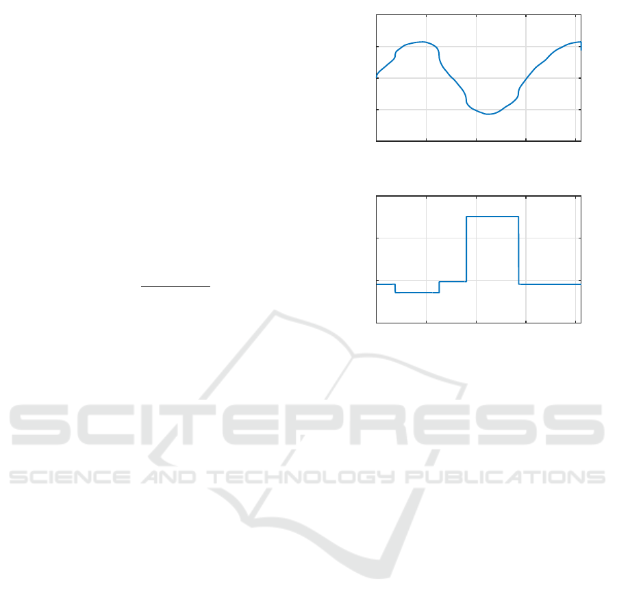
DP-SEO Results Analysis
In order to validate the proposed offline optimization,
it is performed several DP-SEO in different elemen-
tary conditions of slope and desired velocity progress
(constant speed (v
0
= v
f
), acceleration (v
0
< v
f
) and
deceleration (v
0
> v
f
) phases) for a fixed distance D,
K number of ∆D and Λ. Figures 6-7 show the av-
erage energy consumption for different slopes θ for
aforementioned phases. It can be seen that the energy
consumption increases with a bigger θ. A bigger bus
weight also increases the fuel consumption. To keep
the cruise speed on the downhill slope (negative θ),
the acceleration produced by the bus’ own dynamics
is enough (sometimes even excessive and it is neces-
sary to apply a negative torque). So on the downhill
slope the EM part is 100% for deceleration and cruise
speed phases. When accelerating, the EM torque goes
to its peak with the increase of the uphill slope, and it
is complemented by the HM (via ICE), so we can see
that HM ratio increases.
Figure 6: Average energy consumption for different slopes.
Even if the proposed strategy of the DP-SEO gives
good optimal results (all the possible states are ex-
plored and the global minimum is found), neverthe-
less it is too time consuming. However, from the
results of the optimization presented above, the op-
Dynamic Programming Resolution and Database Knowledge for Online Predictive Energy Management of Hybrid Vehicles
137

Figure 7: Average power split for different slopes.
timal offline solutions can be used online in order to
generate the sub-optimal solutions. For that purpose,
the optimal profiles were generated offline for the dis-
tance of ∆d = 21 m (chosen prediction horizon), with
different ∆v for several masses and slopes. Different
scenarios (for acceleration, deceleration, maintaining
the same speed) were simulated and for each simula-
tion configuration an optimal speed profile and related
power split are obtained.
The Optimal Profiles Database based on DP
(OPD-DP) was built for all the possible combination
of velocities from 0 to 15 m/s with ∆v = 1 m/s, the
bus weight varies from 13 to 15 tonnes with ∆M = 0.5
tonne, and the slope angle value ranges from -5
◦
to 5
◦
.
Based on the offline optimal solutions, OPD-DP will
be used to generate the speed profiles and the related
power split in a real-time system.
The multi-dimensional OPD-DP is used for on-
line speed profile and its power split generation.
The scheme of the online control implementation
is presented in Figure 8. The inputs of the multi-
dimensional OPD-DP are the road profile (x,y, θ), the
bus weight, the current speed and the driver’s refer-
ence (desired) speed, and estimated SOC value (this
block is detailed later). Each 21 meters this block
generates the sub-optimal speed profile reference and
torque split depending on the current state of the vehi-
cle and the road profile. The bus weight is considered
constant to travel from one bus station to another, thus
the weight is susceptible to change only after each bus
station. The driver’s command must be followed as
precise as possible due to the safety measures, ensur-
ing the collision avoidance.
The OPD-DP generates the sub-optimal profile
references, as well as T
EM
and T
HM
set points. The set
point torques sent to EM and HM local controllers,
which generate the control input to the motors (I
EM
EM current, D
HM
HM displacement).
Knowing that the multidimensional OPD-DP has
only finite set of values for the parameters (slope θ,
weight M, etc.), it is very important to have a mean to
use this Database even for values not belonging to it.
To solve this problem, below it is proposed a Multidi-
mensional interpolation method.
4.1.1 Multidimensional Interpolation
There are several possible ways to approximate the
actual optimal profile to follow. In our approach,
the Linear Multidimensional (LMD) interpolation
method was used to approximate the optimal speed
profile and the powersplit vector (LaValle, 2006). As
a desired velocity value v lies between two values in
the OPD-DP, the weighted sum of the lower bound
speed v
UB
and the upper bound speed v
LB
are applied
to generate the speed profile:
v
opt
= ζ
v
v
LB
+ (1 − ζ
v
)v
UB
(17)
The weight coefficient ζ
v
is obtained as follows:
ζ
v
= 1 −
v − v
LB
v
UB
− v
LB
(18)
The weight coefficients applied to calculate the cor-
responding power split Λ
opt
, depend on the current
speed v, the bus weight M, and the road slope θ. This
results into three dimensional interpolation function
given as follows:
Λ
opt
(v, M, θ) = ζ
v
ζ
M
ζ
θ
Λ(v
LB
,M
LB
,θ
LB
)+
(1 − ζ
v
)ζ
M
ζ
θ
Λ(v
UB
,M
LB
,θ
LB
)+
ζ
v
(1 − ζ
M
)ζ
θ
Λ(v
LB
,M
UB
,θ
LB
)+
ζ
v
ζ
M
(1 − ζ
θ
)Λ(v
LB
,M
LB
,θ
UB
)+
(1 − ζ
v
)(1 − ζ
M
)ζ
θ
Λ(v
UB
,M
UB
,θ
LB
)+
(1 − ζ
v
)ζ
M
(1 − ζ
θ
)Λ(v
UB
,M
LB
,θ
UB
)+
ζ
v
(1 − ζ
M
)(1 − ζ
θ
)Λ(v
LB
,M
UB
,θ
UB
)+
(1 − ζ
v
)(1 − ζ
M
)(1 − ζ
θ
)Λ(v
UB
,M
UB
,θ
UB
) (19)
where Λ
opt
is the power split vector, and weight coef-
ficients ζ
M
and ζ
θ
are calculated as follows:
ζ
M
= 1 −
M − M
LB
M
UB
− M
LB
(20)
ζ
θ
= 1 −
θ − θ
LB
θ
UB
− θ
LB
(21)
with indexes LB - lower bound and U B - upper bound
of the corresponding parameter.
To illustrate how this method works in 3D, let us
fix speed parameters, and suppose that the powersplit
λ change depends only on the variation of the bus
weight and the road slope. Figure 9 illustrates the case
when for different combinations of weight and slope
angle, we have four known values of λ stored in the
OPD-DP. Now let us address the case when weight
and slope angle values lie in between the known data.
This method permits to calculate the corresponding
powersplit.
ICINCO 2017 - 14th International Conference on Informatics in Control, Automation and Robotics
138
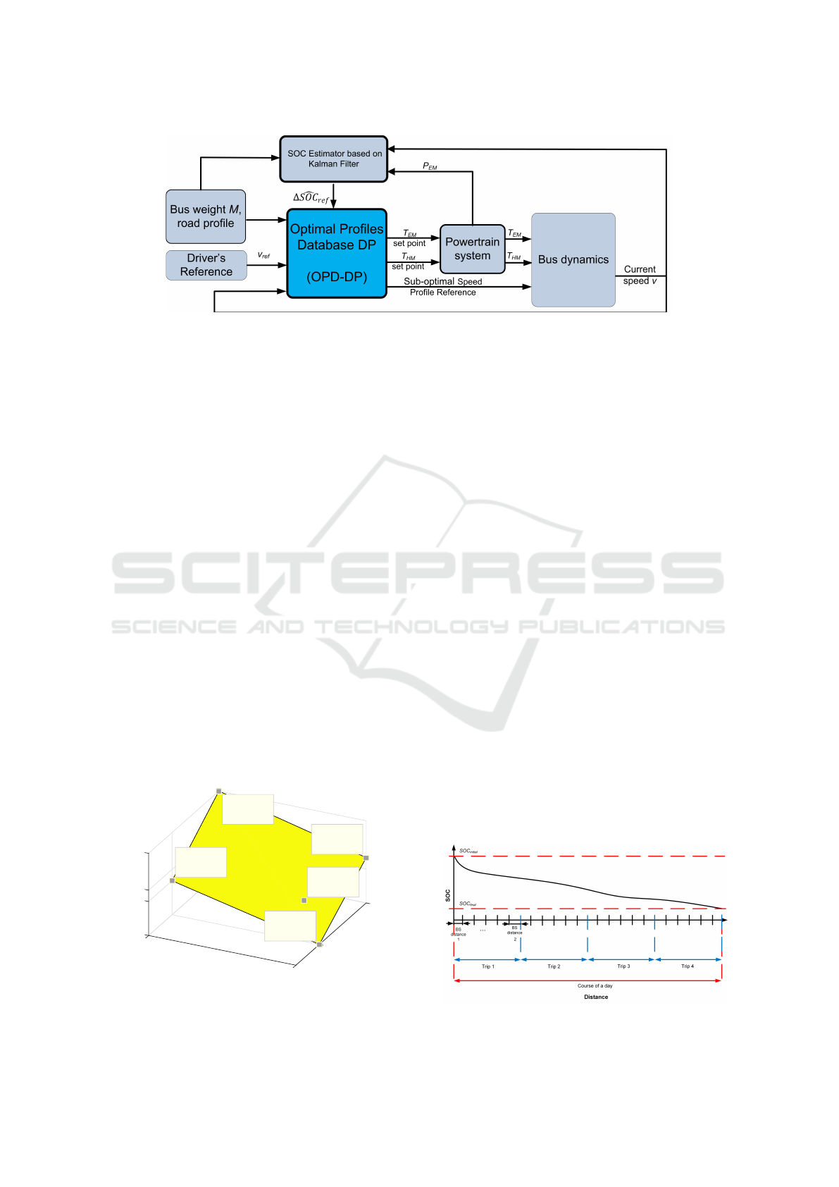
Figure 8: Scheme of the online sub-optimal speed profiles and its power split generation.
4.1.2 SOC Estimator based on Kalman Filter
The BUSINOVA bus is a plug-in hybrid electric vehi-
cle and its standard functioning time is 8 hours a day
(so called “course of a day”). Figure 10 illustrates the
spatial bounds of a bus running cycle. The bus travels
from its starting location to another route terminus,
stopping at bus stations (BS) along the route to allow
passengers to board and to alight. This movement is
called a trip. By the end of a day, the bus reaches
its SOC
min
value and can be recharged during all the
night long to ensure the service the next day.
In this work, the principle idea is to consider that
a better usage of the electric energy is such that it is
available until the end of the day (during 8 hour op-
erational cycle), and this is considered as an optimal
functioning of the bus. The working hypothesis be-
hind this assumption is to use the maximum amount
of energy that can be consumed from the battery in
one day driving so that the battery energy is spread
as uniformly as possible in one working day. This
implies the smooth battery discharging rate (C-rate),
avoidance of the high or low SOC and excessive depth
of charge, which lead to a high rate of battery capacity
loss (Tang et al., 2015) (Choi and Lim, 2002) (Brous-
sely et al., 2005). As Li-ion batteries represent a big
Bus Weight [ton]
13
13.2
1
Road Slope [°]
0
0.63
0.75
0.79
0.92
Powersplit λ
Weight: 13.2
Slope angle: 1
Powersplit: 0.63
Weight: 13.2
Slope angle: 0
Powersplit: 0.75
Weight: 13
Slope angle: 0
Powersplit: 0.92
Weight: 13
Slope angle: 1
Powersplit: 0.79
Weight: 13.14
Slope angle: 0.8
Powersplit: 0.72
Figure 9: Linear Multi-dimensional Interpolation method
illustration.
part of a vehicle cost, the clear interest is to prolon-
gate the battery life. For that purpose a SOC Estima-
tor based on Kalman Filter (Welch and Bishop, 1995)
(Grewal, 2011) is proposed.
It is assumed that the traffic data are measured and
collected, so that for each Trip, and BS distance there
is an amount of ∆SOC = f (E
EM
) that is permitted to
consume according to the statistical analysis, depend-
ing on an average congestion level, travel distance,
average velocity, etc. (Sun et al., 2015) (Van Keulen
et al., 2010b). The Kalman filter addresses the general
problem of trying to estimate the state x of a discrete-
time controlled process that is governed by the linear
stochastic difference equation:
x
k
= Ax
k−1
+ Bu
k
+ w
k
(22)
with measurements z:
z
k
= Hx
k
+ v
k
(23)
Matrix A in the difference equation 22 relates the state
at the previous step k − 1 to the state at the current
step k. The matrix B relates the optional control in-
put u to the state x. The matrix H in the measurement
equation 23 relates the state x to the measurement z
k
.
The random variables w
k
and z
k
represent the process
and measurement noise, respectively. In our case, the
state vector x = [E
EM
P
EM
]
T
, which is a total elec-
tric energy consumed during a trip and instantaneous
electric motor power, respectively. The control input
Figure 10: Spatial bounds of a bus running cycle.
Dynamic Programming Resolution and Database Knowledge for Online Predictive Energy Management of Hybrid Vehicles
139
u = T
EM
ω
EM
is a product of electric motor torque and
its speed.
A predicted state is calculated according to the
equation 22:
x
k
p
= Ax
k−1
+ Bu
k
+ w
k
(24)
A Predicted Process Covariance Matrix is calculated
as follows:
P
k
p
= AP
k−1
A
T
+ Q
k
(25)
where P
k−1
is previous step Process Covariance Ma-
trix, Q
k
stands for process Noise Covariance Matrix
associated with noisy control inputs.
To update the measurements, the following three
steps are carried out:
1. Calculation of the Kalman Gain KG:
KG =
P
k
p
H
T
HP
k
p
H
T
+ R
(26)
where R is Observation Errors Matrix.
2. Calculation of the current state:
x
k
= x
k
p
+ KG(z
k
− Hx
k
p
) (27)
3. Next step is updating a Process Covariance Ma-
trix:
P
k
= (I − KG · H)P
k
p
(28)
with I identity matrix.
In this manner,
ˆ
∆SOC
k
= f (E
EM
) is estimated at each
step k in order to respect SOC
min
at the end of the bus
day work. The value of
ˆ
∆SOC
k
is sent to the OPD-
DP block to find the solution which respects the given
constraint and choose an appropriate powersplit. The
simulation results for a specific scenario are demon-
strated in the next section.
5 SIMULATION RESULTS
It is presented below several results of the use of the
OPD-DP based real time predictive energy optimiza-
tion. The Kalman Filter is used to predict the SOC
and to constrain the use of the battery. Two scenarios
are proposed. For both of them the bus travels a trip
consisting of five Bus Station distances.
1. The bus arrives at all the Bus Stations without
stopping at the traffic lights and without being
stuck in a traffic jam.
2. In this case, at some points it had to stop because
of the traffic lights or before the vehicle ahead,
which entailed underspecified stops along the trip.
Distance [m]
0 500 1000 1500 2000
Road Slope [°]
-2
-1
0
1
2
Road Profile
Distance [m]
0 500 1000 1500 2000
Weight [kg]
× 10
4
1.3
1.35
1.4
1.45
Bus Weight
Figure 11: Road slope and bus weight.
Road profile and the weight of the bus change dur-
ing the trip (cf. Figure 11). However, the weight
changes only after each bus stop when people get on
or get off the bus. It is considered in this simula-
tion that the road-tire frictional coefficient, which de-
pends on the surface where the bus moves and on the
weather conditions, is constant and equal to 1, which
corresponds to the dry pavement (Ming, 1997).
The value of the SOC
min
in the end of the trip re-
mained the same. Basically, the SOC
initial
= 90%,
and in the end of the trip must be around SOC
min
=
87.79%. Total trip distance is 2 km (more precisely
2058m).
Figure 12 represents the results of the first sce-
nario. The first figure shows the obtained speed pro-
file. Red crosses indicate the driver’s demanded speed
at each ∆d. The speed tracking of the driver’s com-
mand is well followed. The figure below shows bat-
tery SOC trajectory. It can be seen that by the end of
the trip we tend to the SOC
min
. The last graph shows
the power split value λ. The applied notation is as fol-
low: λ = 1 corresponds to 100% electric mode, λ = 0
corresponds to 100% hydraulic mode (via ICE), and
λ = −0.1 corresponds to regenerative mode.
Figure 13 represents the second scenario. In this
case, we can see that at the distance ≈500m there is a
non-planned stop, as well as at the distance ≈1200m,
etc. Although the speed profile changed, the online
energy optimization strategy is adapted in such a man-
ICINCO 2017 - 14th International Conference on Informatics in Control, Automation and Robotics
140
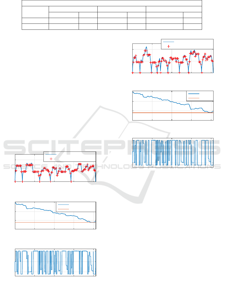
Table 1: Comparison of the ODP-DP online strategy and the offline DP.
SOC
min
= 87.79 %
OPD-DP DP DP vs OPD-DP
SOC
f inal
, % Fuel, l SOC
f inal
, % Fuel, l SOC
f inal
, % Fuel, l
Scenario 1 87.85 0.195 88.02 0.178 -0.02 0.017
Scenario 2 87.84 0.228 87.88 0.189 -0.03 0.039
ner that it will always tend to SOC
min
at the end of
the trip. We can see this adaptation, according to the
change in λ.
The OPD-DP based real time predictive energy
optimization is compared to the offline DP. The of-
fline DP based optimization was carried out for the
same speed profiles. Table 1 shows that the obtained
results are close to the offline DP solution.
6 CONCLUSIONS AND
PROSPECTS
In this paper, the DP technique is used to simulta-
neously generate the optimal velocity profile and its
power split strategy in order to ensure the electric en-
ergy and fuel economy, respecting passengers com-
fort (by limiting the acceleration/deceleration). As the
Distance [m]
0 500 1000 1500 2000
Speed [km/h]
0
20
40
Speed profile
LMD Interpolation
Driver command each ∆ d
Distance [m]
0 500 1000 1500 2000
SOC [%]
87
88
89
90
Battery SOC
LMD Interpolation
SOCmin
Distance [m]
0 500 1000 1500 2000
Powersplit λ
0
0.5
1
Powersplit ratio
Figure 12: First scenario: 1) speed profile 2) actual SOC
and the desired value in the end of the trip SOC
min
3) power
split λ.
Distance [m]
0 500 1000 1500 2000
Speed [km/h]
0
20
40
Speed profile
LMD Int
Driver command each ∆ d
Distance [m]
0 500 1000 1500 2000
SOC [%]
87
88
89
90
Battery SOC
LMD Int
SOCmin
Distance [m]
0 500 1000 1500 2000
Powersplit λ
0
0.5
1
Powersplit ratio
Figure 13: Second scenario: 1) speed profile 2) actual SOC
and the desired value in the end of the trip SOC
min
3) power
split λ.
dynamics of the electric motor and engine are differ-
ent, not all the energy management configurations are
feasible. This aspect is taken into account in the DP-
SEO algorithm.
Thereafter, the offline optimal solutions of the
DP based optimization were collected into a multi-
dimensional OPD-DP for the online implementation
for a priori unknown traffic conditions for instance.
To cope with the problem of the finite set of sample
points in the database, a Linear Multidimensional in-
terpolation was used to obtain the values at all other
points. The SOC estimator based on Kalman Filter
was used to restrict the use of the battery through-
out the cycles and allows us to have smooth bat-
tery discharge rate, guaranteeing a regular electric en-
ergy consumption without falling below the minimum
SOC value. The results obtained by Online Predictive
Energy Management strategy were compared to DP
Dynamic Programming Resolution and Database Knowledge for Online Predictive Energy Management of Hybrid Vehicles
141

solutions obtained offline, and it was shown that near
optimal results were obtained in real-time application.
The influence of road-tire frictional coefficient on the
online energy management strategy will be studied in
near future. Later, the given approach will be imple-
mented in the real bus.
ACKNOWLEDGEMENTS
This project is supported by the ADEME (Agence De
l’Environnement et de la Matrise de l’Energie) for the
National French program “Investissement d’Avenir”,
through BUSINOVA Evolution project.
REFERENCES
Abdrakhmanov, R. and Adouane, L. (2017). Efficient acc
with stop&go maneuvers for hybrid vehicle with on-
line sub-optimal energy management. In RoMoCo’17,
11th International Workshop on Robot Motion and
Control, Wasowo-Poland, 3-5 July.
Bayindir, K. C¸ ., G
¨
oz
¨
uk
¨
uc¸
¨
uk, M. A., and Teke, A. (2011).
A comprehensive overview of hybrid electric vehicle:
Powertrain configurations, powertrain control tech-
niques and electronic control units. Energy Conver-
sion and Management, 52(2):1305–1313.
Bellman, R. E. and Dreyfus, S. E. (2015). Applied dynamic
programming. Princeton university press.
Bertsekas, D. P. (1995). Dynamic programming and optimal
control, volume 1. Athena Scientific Belmont, MA.
Broussely, M., Biensan, P., Bonhomme, F., Blanchard, P.,
Herreyre, S., Nechev, K., and Staniewicz, R. (2005).
Main aging mechanisms in li ion batteries. Journal of
power sources, 146(1):90–96.
Chen, B.-C., Wu, Y.-Y., and Tsai, H.-C. (2014). Design and
analysis of power management strategy for range ex-
tended electric vehicle using dynamic programming.
Applied Energy, 113:1764–1774.
Cheng, Y., Lataire, P., et al. (2007). Research and test plat-
form for hybrid electric vehicle with the super capac-
itor based energy storage. In Power Electronics and
Applications, 2007 European Conference on, pages 1–
10. IEEE.
Choi, S. S. and Lim, H. S. (2002). Factors that affect
cycle-life and possible degradation mechanisms of a
li-ion cell based on licoo 2. Journal of Power Sources,
111(1):130–136.
Dib, W., Chasse, A., Moulin, P., Sciarretta, A., and Corde,
G. (2014). Optimal energy management for an electric
vehicle in eco-driving applications. Control Engineer-
ing Practice, 29:299–307.
Grewal, M. S. (2011). Kalman filtering. Springer.
Heppeler, G., Sonntag, M., and Sawodny, O. (2014). Fuel
efficiency analysis for simultaneous optimization of
the velocity trajectory and the energy management in
hybrid electric vehicles. IFAC Proceedings Volumes,
47(3):6612–6617.
Heppeler, G., Sonntag, M., Wohlhaupter, U., and Sawodny,
O. (2016). Predictive planning of optimal velocity and
state of charge trajectories for hybrid electric vehicles.
Control Engineering Practice.
Kamal, E., Adouane, L., Abdrakhmanov, R., and Ouddah,
N. (2017). Hierarchical and adaptive neuro-fuzzy con-
trol for intelligent energy management in hybrid elec-
tric vehicles. In IFAC World Congress, Toulouse-
France.
Kim, T. S., Manzie, C., and Sharma, R. (2009). Model pre-
dictive control of velocity and torque split in a paral-
lel hybrid vehicle. In Systems, Man and Cybernetics,
2009. SMC 2009. IEEE International Conference on,
pages 2014–2019. IEEE.
Kitayama, S., Saikyo, M., Nishio, Y., and Tsutsumi, K.
(2015). Torque control strategy and optimization for
fuel consumption and emission reduction in parallel
hybrid electric vehicles. Structural and Multidisci-
plinary Optimization, 52(3):595–611.
LaValle, S. M. (2006). Planning algorithms. Cambridge
university press.
Ming, Q. (1997). Sliding mode controller design for abs
system. PhD thesis, Virginia Tech.
Murphey, Y. L. (2008). Intelligent vehicle power manage-
ment: An overview. In Computational Intelligence in
Automotive Applications, pages 169–190. Springer.
Ozatay, E., Onori, S., Wollaeger, J., Ozguner, U., Riz-
zoni, G., Filev, D., Michelini, J., and Di Cairano,
S. (2014). Cloud-based velocity profile optimization
for everyday driving: A dynamic-programming-based
solution. Intelligent Transportation Systems, IEEE
Transactions on, 15(6):2491–2505.
Pei, D. and Leamy, M. J. (2013). Dynamic programming-
informed equivalent cost minimization control strate-
gies for hybrid-electric vehicles. Journal of Dynamic
Systems, Measurement, and Control, 135(5):051013.
Pisu, P. and Rizzoni, G. (2007). A comparative study of
supervisory control strategies for hybrid electric vehi-
cles. IEEE Transactions on Control Systems Technol-
ogy, 15(3):506–518.
Rousseau, G. (2008). V
´
ehicule hybride et commande op-
timale. PhD thesis,
´
Ecole Nationale Sup
´
erieure des
Mines de Paris.
Shen, D., Bensch, V., and Miiller, S. (2015). Model predic-
tive energy management for a range extender hybrid
vehicle using map information. IFAC-PapersOnLine,
48(15):263–270.
Song, Z., Hofmann, H., Li, J., Han, X., and Ouyang, M.
(2015). Optimization for a hybrid energy storage sys-
tem in electric vehicles using dynamic programing ap-
proach. Applied Energy, 139:151–162.
Sun, C., Sun, F., Hu, X., Hedrick, J. K., and Moura, S.
(2015). Integrating traffic velocity data into predic-
tive energy management of plug-in hybrid electric ve-
hicles. In American Control Conference (ACC), 2015,
pages 3267–3272. IEEE.
Tang, L., Rizzoni, G., and Onori, S. (2015). Energy man-
agement strategy for hevs including battery life opti-
ICINCO 2017 - 14th International Conference on Informatics in Control, Automation and Robotics
142

mization. IEEE Transactions on Transportation Elec-
trification, 1(3):211–222.
Tokekar, P., Karnad, N., and Isler, V. (2014). Energy-
optimal trajectory planning for car-like robots. Au-
tonomous Robots, 37(3):279–300.
Van Keulen, T., de Jager, B., Foster, D., and Steinbuch, M.
(2010a). Velocity trajectory optimization in hybrid
electric trucks. In Proceedings of the 2010 American
Control Conference, pages 5074–5079. IEEE.
Van Keulen, T., de Jager, B., Kessels, J., and Steinbuch, M.
(2010b). Energy management in hybrid electric ve-
hicles: Benefit of prediction. IFAC Proceedings Vol-
umes, 43(7):264–269.
Welch, G. and Bishop, G. (1995). An introduction to the
kalman filter.
Zeng, X. (2009). Improving the energy density of hydraulic
hybridvehicle (hhvs) and evaluating plug-in hhvs.
Zhang, Y., Jiao, X., Li, L., Yang, C., Zhang, L., and Song,
J. (2014). A hybrid dynamic programming-rule based
algorithm for real-time energy optimization of plug-
in hybrid electric bus. Science China Technological
Sciences, 57(12):2542–2550.
Dynamic Programming Resolution and Database Knowledge for Online Predictive Energy Management of Hybrid Vehicles
143
