
Robust Energy Management Strategy based on the Battery Fault
Management for Hydraulic-electric Hybrid Vehicle
Elkhatib Kamal and Lounis Adouane
Institut Pascal/IMobS3, UCA/SIGMA UMR CNRS 6602, Clermont-Ferrand, France
Keywords:
Artificial Intelligence, Battery Management System, Fuzzy Observer, Hybrid Electric Vehicles, Power
Management Strategy, Sensor Faults, Takagi-sugeno Fuzzy Model.
Abstract:
This paper deals with a robust energy management strategy, including a battery fault detection and compen-
sation for a hydraulic-electric hybrid vehicle. The overall control and management strategy aims to minimize
total energy consumption while ensuring a better battery life. Many power management strategies do not con-
sider battery faults which could accelerate battery aging, decreasing thus its life and could cause also thermal
runaway, which may cause fire and battery explosions. Therefore, battery fault tolerant control to guarantee the
battery performance is also proposed in this paper. The proposed strategy consists of fuzzy supervisory fault
management at the highest level (the second). This level is responsible to detect and compensate the battery
faults, generating optimal mode and healthy state of charge set point for first level to prevent overcharge or/and
over-discharge. In the first level, an energy management strategy is developed based on neural fuzzy strategy
to manage power distribution between electric motor and engine. Then, there are robust fuzzy controllers
to regulate the set points of each vehicle subsystems to reach the best operational performance. The Truck-
Maker/MATLAB simulation results confirm that the proposed architecture can satisfy power requirement for
any unknown driving cycles and compensate battery faults effect.
1 INTRODUCTION
Growing environmental concerns coupled to the de-
creasing of fossil fuel energy sources stimulate highly
research on new vehicle technologies. Electric vehi-
cles (EVs) and Hybrid Electric Vehicles (HEV) ap-
pear to be one of the most promising technologies
for reducing fuel consumption and pollutant emis-
sions (Panday and Bansal, 2016). Energy manage-
ment in vehicles is an important issue because it can
significantly influence the performances of the vehi-
cles. Several methods for energy management and
optimization aiming at the minimization of different
cost functions have been published, such as dynamic
programming (Abdrakhmanov and Adouane, 2017),
(Tate et al., 2010), the equivalent consumption min-
imization strategy (Tulpule et al., 2010), Pontrya-
gin’s Minimum Principle (PMP), (Hou et al., 2014)
and genetic algorithm (Martnez et al., 2016). There-
fore, there are nowadays different blending levels of
pure EV and Hybrid Electric Vehicle (HEV) available
on the current automobile market. According to the
blending level, various size, type and number of bat-
tery cells are mounted in HEVs and EVs (Lu et al.,
2013). Unlike conventional fuel, battery cells as an
energy source have stricter requirement on working
environment (Striebel et al., 2005). Many approaches
to power management strategy of hybrid vehicle do
not consider the effect of control strategy on the
faulty battery (Tulpule et al., 2010), (Martnez et al.,
2016), (Kamal et al., 2017b), (Kamal et al., 2017a).
It is known that, Lithium-ion batteries are consid-
ered as the most promising energy storage device in
HEV, due to their inherent benefits of high power and
energy density, long lifespan and low maintenance
cost. These growing demands make the battery per-
formance and life of critical importance. Although
Lithium-ion batteries are known as long-service de-
vices, their lives depend greatly on environmental
condition and operation mode (Maleki and Howard,
2006). Environmental conditions such as overcharg-
ing, overdischarging and the temperature will shorten
service life. In addition, the sensors in the battery
system may present different kinds of failures due to
high temperature, overcharging/overdischarging and
battery design and or vibrations (Xing et al., 2013).
If the current or voltage sensor is faulty, the battery
State of Charge (SOC) estimations may be affected,
92
Kamal, E. and Adouane, L.
Robust Energy Management Strategy based on the Battery Fault Management for Hydraulic-electric Hybrid Vehicle.
DOI: 10.5220/0006429700920103
In Proceedings of the 14th International Conference on Informatics in Control, Automation and Robotics (ICINCO 2017) - Volume 1, pages 92-103
ISBN: 978-989-758-263-9
Copyright © 2017 by SCITEPRESS – Science and Technology Publications, Lda. All rights reserved

this may result in the battery suffering from over-
charge or/and over-discharge (Plett, 2004). This will
accelerate the battery aging, decrease the battery life
and cause thermal runaway, which in the worst cases
may cause fire and battery explosions and then the
fire and the vehicle destruction. Therefore, a reli-
able battery sensor and actuator fault tolerant con-
trol to guarantee the battery performance, safety and
life while simultaneously minimizing the total energy
consumption (summation of electric battery and fuel)
of Hydraulic-Electric Hybrid Vehicle (HHEVs) are
addressed in this paper. Robust Energy Management
Strategy (REMS) is proposed based on neural net-
working, fuzzy logic, fuzzy observer and rule based
optimization. The REMS has been realized based on
the analysis results of the energy management strat-
egy presented in (Kamal et al., 2017a). An Intelligent
Supervisory Switching Mode and Battery Manage-
ment Controller (ISSMBMC) based on fuzzy logic,
fuzzy observer and rule based optimization is devel-
oped in the second level (the highest level) that is ca-
pable of managing all of the possible bus operation
modes, compensate the battery faults, generating op-
timal mode and SOC set points for first level. The pro-
posed algorithm in this level based on fuzzy observer
to estimate the faults is then investigated for the de-
tection, isolation and compensation of sensor (voltage
sensor) and actuator (current sensor) battery faults.
A Takagi-Sugeno’s (TS) fuzzy model is adopted for
fuzzy modeling of the system and establishing fuzzy
state observers. The concept of Parallel Distributed
Compensation (PDC) (Kamal et al., 2017b) is em-
ployed to design fuzzy control and fuzzy observers
from the TS fuzzy models. Sufficient conditions are
derived for robust stabilization in the sense of Lya-
punov stability, for sensor faults, actuator faults and
state variables unavailable for measurements. The
sufficient conditions are formulated in the format of
Linear Matrix Inequalities (LMI). The energy man-
agement strategy in the first level is formulated based
on neural fuzzy strategy for minimizing the total en-
ergy consumption while meeting the driver power de-
mand. This level decides the optimal combination of
power sharing between different energy sources (bat-
tery and Internal Combustion Engine (ICE)) to maxi-
mize overall vehicle efficiency. In addition, there are
adaptive fuzzy controller based on (Hamed and Al-
mobaied, 2011) which are used to track the set points
of Electric Motor (EM) and Hydraulic Motor (HM)
via the ICE, in order to reach peak performance and
acceptable operation indexes while taking into con-
sideration the dynamic behavior of EM, ICE and HM.
The proposed strategy can be used for both offline
and online scenarios. Since this paper makes more
the focus on the second Level 2, only while the first
level is designed based on (Kamal et al., 2017a). The
proposed strategies, implemented in simulation using
TruckMaker software, confirm that the proposed ar-
chitecture can satisfy the power requirement for any
unknown driving cycles and compensate the effect of
the battery faults. The results of this paper support
that the proposed strategy is capable of: (i) detection,
isolation and compensation the battery voltage sensor
fault and battery currant actuator fault; (ii) minimiz-
ing the total energy consumption; (iii) being imple-
mented in real-time; (iv) it does not require before-
hand a-priori knowledge of the driving event; (v) re-
ducing the number of rules needed in fuzzy control;
(vi) maintaining the ICE near its optimal operating
range; (vii) keeping SOC within the range which pro-
motes battery longevity.
In addition to the main objectives in this paper, an
accurate and reliable model of the studied hybrid ve-
hicle is also highlighted in Section 2. The studied ve-
hicle is a hybrid bus, based on a series-parallel power-
split hybrid architecture. This hybrid bus is called
BUSINOVA and is developed by SAFRA company
(cf. Figures 1 and 2).
The paper is organized as follows. The overall
HHEV description and modeling is given in section 2.
In section 3, the proposed robust energy management
Strategy structure is developed. Section 4 shows the
experiment model validation and fault effects analy-
sis. Section 5 is devoted to give a conclusion and
some prospects.
2 OVERALL HHEV MODELING
AND DESCRIPTION
In order to study and develop an efficient energy man-
agement strategy including the battery fault manage-
ment for HHEVs, an accurate and reliable model
is needed. Therefore, this section will make a fo-
cus on the modelling and analysis of the studied
HHEV with its different operations modes. Truck-
Maker/MATLAB software is used to simulate pre-
cisely the studied hybrid vehicle.
2.1 HHEV Description and Modelling
The studied vehicle corresponds to BUSINOVA bus
shown in Figure 1. This bus has three actuations:
electric, hydraulic and thermal. The principle source
of the propulsion in the vehicle is an EM which may
be supplemented by the HM via ICE. The hydraulic
system block consists of variable-displacement of
Robust Energy Management Strategy based on the Battery Fault Management for Hydraulic-electric Hybrid Vehicle
93
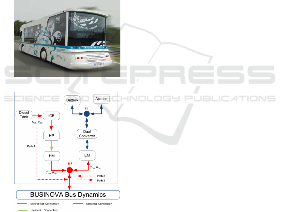
HM, and an ICE driven fixed-displacement of Hy-
draulic Pump (HP). The ICE is directly connected
to a fixed displacement pump, which converts engine
mechanical power into hydraulic power as shown in
the vehicle configuration and power flow diagram (cf.
Figure 2). The BUSINOVA is equipped with electric,
hydrostatic and dissipative braking capabilities. The
dissipative brake is a mechanical brake which dissi-
pates energy as heat through friction. Electric and hy-
drostatic brakes are linked to the hydraulic motor in a
regenerative braking system that is capable of recov-
ering a portion of the kinetic energy of braking that
would otherwise be dissipated. An Electrical Junction
(EJ) exists between the battery, accessories (Access)
and dual converter as well as a Mechanical Junction
(MJ) between the HM and EM.
Figure 1: BUSINOVA a Hydraulic-Electric Hybrid bus.
Figure 2: BUSINOVA bus configuration and power flow.
T
ICE
, T
HM
, T
EM
and P
ICE
, P
HM
, P
EM
are the produced
torque and power for the ICE, HM and EM, respectively.
2.2 Motoring Models
The BUSINOVA can operate according to the modes
described below:
• The propulsion is fully supplied by EM (mode 1),
• The bus is actuated by the HM via ICE (mode 2),
• The mode 3 implies the hybrid operation of the
EM and the HM via ICE,
• Recharge of the electric battery via ICE (mode 4),
• The regenerative braking (mode 5).
In this section, we will present the HM model through
ICE and the EM models as the following.
2.2.1 Hydraulic Motor Coupled to Internal
Combustion Engine
In this paper, ICE torque versus ICE speed is directly
derived from the ICE fuel consumption model. The
fuel flow rate ˙m
f
of the ICE is defined by
˙m
f
= f
ICE
(T
ICE
, ω
ICE
) (1)
where ω
ICE
is the ICE rotational speed. The func-
tion f
ICE
is obtained from the ICE bench tests. The
power consumed by the ICE (P
ICE
) is given by
P
ICE
= ˙m
f
(T
ICE
, ω
ICE
)Q, (i.e., P
ICE
is the instanta-
neous power of the fuel expressed in terms of ˙m
f
and
the lower heating value of the fuel (Q = 43MJ/kg)).
2.2.2 Electric Motor
The studied hybrid bus uses a 103 KW permanent
magnet synchronous machine as EM. The powers re-
quired for the EM were calculated from the known
EM torque and speed by using EM efficiency curve.
The output torque T
EM
of the EM is defined by
T
EM
= f
EM
(P
EM
, ω
EM
) (2)
where P
EM
is the EM input power, ω
EM
is the EM
current speed. The function f
EM
is also obtained from
the EM bench test. The EM can operate in motor or
generator mode.
2.3 BUSINOVA Battery Modeling
One of the most important is the SOC for the battery
fault management strategy, since during the operation
of the battery, the SOC cannot be measured directly.
Therefore the estimation of the SOC is needed. To
obtain a reliable SOC estimation, an accurate model
of the battery is needed. Different Lithium-ion bat-
tery models are developed in the literature for various
purposes. The equivalent electrical circuit models and
the electrochemical models are the most widely used
in EV studies. The electrical circuit models use equiv-
alent electrical circuits to show current-voltage char-
acteristics of batteries by using voltage and current
sources, capacitors, and resistors. For BUSINOVA
ICINCO 2017 - 14th International Conference on Informatics in Control, Automation and Robotics
94

bus battery model, we select the model presented in
(Sepasi et al., 2014) as a reference model (cf. Fig-
ure 3). The selected battery model consists of two
parts of the Energy Balance Circuit (EBC) and Volt-
age Response Circuit (VRS). The EBC delivers SOC
to the VRS. To cover all BUSINOVA bus battery prac-
tical conditions, the model paramaters are considered
to be a function of SOC, current, and temperature.
Moreover to increase accuracy, this model has sep-
arate operating functions at low and high temperature
for charging and discharging. Using Kirchoff’s volt-
age law, the electrical behavior of the practical model
can be expressed as follows:
V
bat
= V
oc
+ I
bat
R
o
+V
1
(t) + V
2
(t) (3)
where V
bat
is the battery terminal voltage, V
oc
is the
battery open circuit voltage (OCV), I
bat
is the load
current, t is the time varying, V
1
, V
2
are the voltages
across R
1
//C
1
and R
2
//C
2
, where R
1
, R
2
and C
1
, C
2
are
the RC branch resistors and capacitors, respectively,
R
o
is the internal resistance, which consists to the bulk
resistance and surface layer impedance and T is the
battery temperature. The dynamics of the nonlinear
battery behavior can be characterized by the following
equations,
˙x(t) = Ax(t) + Bu(t)
y(t) = C(x)x(t)
(4)
Where x(t) =
V
1
(t)
V
2
(t)
SOC
, A =
1
R
1
C
1
0 0
0
1
R
2
C
2
0
0 0 0
,
B =
1
C
1
1
C
2
η
C
n
, C(x) =
q
1
(x)
1
q
2
(x)
T
, u(t) = I
bat
and y(t) =
V
bat
where q
1
(x) =
(I
bat
R
o
+V
1
(t))
V
1
(t)
and q
2
(x) =
V
oc
SOC
are
the nonlinear terms. Equation (4) indicates that the
matrix C(x) is not fixed, but change as functions of
state variables, thus making the model to be nonlinear.
Figure 3: BUSINOVA Lithium-ion Battery equivalent elec-
trical model.
3 PROPOSED ROBUST ENERGY
MANAGEMENT STRATEGY
(REMS)
After proposing an accurate model for the BUSI-
NOVA bus, the aim of this section is to make the focus
on the proposed REMS, embedded in the bus in order
to minimize its total energy consumption while max-
imizing the global vehicle efficiency and compensate
the battery faults. Therefore, in this section, an REMS
structure is proposed which is capable of meeting var-
ious objectives including optimized power flow man-
agement, maintaining high operational efficiency of
the ICE, and balancing EM and battery charge to
maximize the global vehicle efficiency and detect and
compensate the effect of the battery faults.
This proposed strategy consists of two control lev-
els (cf. Figure 4). The second level has been devel-
oped by fuzzy strategy and fuzzy observer which de-
cide which operating mode or combination of modes
would be most efficient based on a healthy SOC (cf.
section 3.1). This level consists of two blocks, the
first block of this level is Battery Management Fuzzy
Fault Tolerant Controller (BMFFTC) to detect and
the compensate the battery faults and generate the
healthy SOC for the Fuzzy Switching Mode Con-
troller (FSMC) which selects the optimal mode for
the second level. At the first level (cf. section 3.2),
an energy management strategy has been developed
for power splitting which decide the optimal com-
bination of power sharing between different energy
sources to maximize the overall vehicle efficiency. In
addition, adaptive fuzzy controllers are used to track
the set points of EM and HM via the ICE, in order
to reach peak performance and acceptable operation
indexes while taken in consideration of the dynamic
behavior of EM, ICE and HM. In this paper, we will
focus more on level 2 (cf. section 3.1), while the first
level is designed based on (Kamal et al., 2017a).
3.1 Intelligent Supervisory Switching
Mode and Battery Management
Controller (Level 2: ISSMBMC)
The objective of this section is to optimize the selec-
tion mode and detect and compensate the battery sen-
sor fault (battery terminal voltage sensor) and the ac-
tuator fault (battery input current actuator). This level
is consists of BMFFTC and FSMC blocks to gener-
ate the selected mode and the SOC set point for the
first level. Figure 5 shows the block diagram of the
proposed level 2 block.
Robust Energy Management Strategy based on the Battery Fault Management for Hydraulic-electric Hybrid Vehicle
95
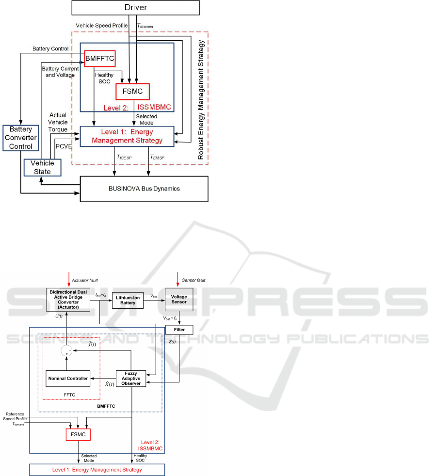
Figure 4: Developed REMS for BUSINOVA bus. In this
figure the following acronyms are used: PCVE (Produced
and Consumed Vehicle Energy); T
demand
(Torque Demand)
which is required to drive the vehicle and is defined by the
global torque set point; T
ICE,SP
is the ICE torque set point
and T
EM,SP
is the EM torque set point.
Figure 5: Schematic of the proposed level 2.
3.1.1 Fuzzy Switching Mode Controller (FSMC)
As mentioned in section 2.2, there are five modes of
operations. In order to improve the studied HHEV op-
eration, the proposed FSMC based on fuzzy logic and
rule based, has to decide which operating mode (or
combination of them) is appropriate. Many parame-
ters (such as the value of SOC for the battery, required
vehicle power, vehicle speed and maximum power
supplied by the battery, etc.) must be considered to
choose the most efficient operation mode to manage
and optimize the power flow. Based on the avail-
able output torque, the pedal position is converted into
torque demand (T
demand
). If T
demand
< 0, the driver
intends to decelerate the vehicle therefore regenera-
tive braking mode is chosen. But, if T
demand
> 0, the
requiring torque is split between EM or/and HM via
ICE. In the proposed algorithm, modes 1, 2, 3, and 4
are selected by fuzzy logic and mode 5 is selected by
traditional logic. Fuzzy logic is well suited for select-
ing between modes 1, 2, 3 and 4, since the range or
boundary is vague and not clearly specified due to the
actual state of the vehicle (masse, velocity, etc.) for
these modes. The ISSMBMC input variables are Ve-
hicle Speed, T
demand
and SOC, and its output variable
is the operation mode (Mode). The fuzzy rule is con-
structed from 27 individual fuzzy rules. An example
of the used rules is given for instance by this one: if
T
demand
is low and SOC is high and vehicle speed is
high then Mode is model 1.
3.1.2 Battery Management Fuzzy Fault Tolerant
Controller (BMFFTC)
The main objective for the BMFFTC is to mange
and control the battery faults and generate the healthy
SOC point for FSMC and the first level which af-
fects the studied HHEV power optimization. This
section presents a systematic fault diagnosis and con-
trol scheme for a battery cell to detect current and/or
voltage sensor faults, and compensate its effect. For
the diagnostic and control scheme implementation,
new Fuzzy Fault Tolerant Control (FFTC) based on
fuzzy adaptive observer is proposed. The algorithm
based on mechanism is used to estimate the faults
then investigated for detection, isolation and accom-
modation of the battery sensor fault (battery terminal
voltage sensor) and the actuator fault (battery input
current actuator). The TS fuzzy model is adopted for
fuzzy modeling of the system and establishing fuzzy
state observers. The concept of PDC (Kamal et al.,
2017b) is employed to design fuzzy control and fuzzy
adaptive observer from the TS fuzzy models. Suffi-
cient conditions are derived for robust stabilization in
the sense of Lyapunov stability. The sufficient con-
ditions are formulated in the format of LMI (Linear
Matrix Inequalities).
The general configuration of BMFFTC is shown
in Figure 5, it is based on the fuzzy adaptive observer
which estimates the sensor and actuator fault and re-
constructs the controller. Fuzzy observer works with
the Lithium-ion battery cell and based on the mea-
sured input current and output voltage, in order to bat-
tery state estimation. In this paper, the sensor fault
or the actuator fault can occur at the same time or
ICINCO 2017 - 14th International Conference on Informatics in Control, Automation and Robotics
96

only one sensor fault is present at a time. In order
to design BMFFTC, we need to represent the battery
model based on TS fuzzy model, design fault estima-
tion based on the fuzzy adaptive observer as the fol-
lowing.
Takagi-Sugeno’s Fuzzy Plant Model with Sensor
and/or Actuator Faults. The overall fuzzy model
achieved by fuzzy blending of each individual plant
rule is given by (Kamal et al., 2012),
˙x(t) =
p
∑
i=1
µ
i
(q(t))[A
i
x(t) + B
i
u(t) + E
ai
f
a
(t)]
y(t) =
p
∑
i=1
µ
i
(q(t))[C
i
x(t) + E
si
f
s
(t)]
(5)
where x(t) is the state vector, u(t) is the control input
vector, y(t) is the output vector, p is the number of
rules of the TS fuzzy model, A
i
∈ κ
n×n
, B
i
∈ κ
n×m
and C
i
∈ κ
g×n
are system, input and output matri-
ces, respectively and q(t) are assumed measurable
variables and do not depend on the sensor faults and
the actuator faults. It is known that µ
i
(q(t)) ≥ 0,
p
∑
i=1
µ
i
(q(t)) = 1, writing µ
i
(q(t)) as µ
i
for simplicity.
Considering also the state Z ∈ κ
g×1
that is a filtered
version of the output y(t) (Edwards, 2006). This state
is given by:
˙
Z(t) =
p
∑
i=1
µ
i
[−A
zi
Z(t) + A
zi
C
i
x(t) + A
zi
E
si
f
s
(t)] (6)
Where −A
zi
κ
r×r
is the stable matrix, from the (5) and
(6), one can obtain the augmented system:
˙
X(t) =
p
∑
i=1
µ
i
[
¯
A
i
X(t) +
¯
B
i
U(t) +
¯
E
i
f(t)]
Y(t) =
p
∑
i=1
µ
i
¯
C
i
X(t)
(7)
where X(t) =
x(t)
Z(t)
, U(t) =
u(t)
0
,
f(t) =
f
a
(t)
f
s
(t)
,
¯
A
i
=
A
i
0
A
zi
C
i
−A
zi
,
¯
B
i
=
B
i
0
0 0
,
¯
E
i
=
E
ai
0
0 A
zi
E
si
and
¯
C
i
=
0
I
,
A
i
=
1
R
1
C
1
0 0
0
1
R
2
C
2
0
0 0 0
, B
i
=
1
C
1
1
C
2
η
C
n
,
Fuzzy Adaptive Observer. In order to estimate the
state and the fault of the battery (4), the following
fuzzy adaptive observer is proposed,
˙
ˆ
X(t) =
p
∑
i=1
µ
i
[
¯
A
i
X(t) +
¯
B
i
U(t)
+
ˆ
E
i
ˆ
f(t) + K
i
(Y(t) −
ˆ
Y(t))] (8)
e
x
(t) = X(t)−
ˆ
X(t)+
ˆ
E
i
ˆ
f(t)+K
i
(Y(t)−
ˆ
Y(t))] (9)
e
y
(t) = Y(t) −
ˆ
Y(t) =
¯
C
i
e
x
(t) (10)
˙
ˆ
f(t) =
p
∑
i=1
µ
i
L
i
( ˙e
y
(t)+e
y
(t)) =
p
∑
i=1
µ
i
L
i
¯
C
i
( ˙e
x
(t)+e
x
(t))
(11)
ˆ
Y(t) =
p
∑
i=1
µ
i
¯
C
i
ˆ
X(t) (12)
Where
ˆ
X(t) is the observer state,
ˆ
Y(t) is the ob-
server output vector,
ˆ
f(t) is an estimation of the sen-
sor and actuator fault f(t), K
i
and L
i
are the observer
gains to be designed. Proposed Fuzzy Fault Tol-
erant Control. In this section, the FFTC synthesis
procedure is developed to deal with a wide range of
sensor faults, and actuator faults while maintaining
the stability of the closed loop battery system. For
simplicity, we make
¯
E
j
=
¯
B
j
E
j
, where, E
j
are known
matrix. For the fuzzy model (5), we construct the fol-
lowing FFTC via the PDC (Kamal et al., 2017b). It is
assumed that the fuzzy system (5) is locally control-
lable. A state-feedback with LMIs is used to design a
controller for each subsystem. The final output of the
FFTC based on online fault estimation is defined by,
U(t) =
p
∑
j=1
µ
j
[G
j
ˆ
X(t) − E
j
ˆ
f(t)] (13)
where, G
i
are the controller gain to be designed, the
sensor and the actuator fault vectors are assumed to
be bounded. The main result for the global asymp-
totic stability of a TS fuzzy model with sensor and
actuator faults are summarized by the following The-
orem 1.
Theorem 1: The TS fuzzy system (7) is asymptot-
ically stabilizable if there exists symmetric and pos-
itive definite matrix P (P>0), some matrices L
i
, K
i
,
and G
j
(i=1,2,. ..,p; j=1,2,...,q), such that the fol-
lowing LMIs are satisfied,
O
A
T
i
+A
i
O− (
B
i
W
j
)
T
− (
B
i
W
j
) < 0 (14)
H
T
bi
P
2
+
P
2
H
bi
−(
D
i
C
i
)
T
− (
D
i
C
i
) < 0 (15)
where O = P
−1
1
, G
j
= W
j
O
−1
,
¯
K
i
=P
−1
2
D
i
,
¯
K
i
=
K
i
L
i
.
Proof. The conditions imposed to develop the The-
orem is shown in the appendix. According to the
analysis above, the procedure for finding the proposed
FFTC controller and the fuzzy adaptive observer for
the battery are summarized as follows.
1. Obtain the mathematical model of the battery to
be controlled (cf. section 2.3).
2. Obtain the TS fuzzy plant model for the system
stated in the previous step by means of a fuzzy
modeling method.
Robust Energy Management Strategy based on the Battery Fault Management for Hydraulic-electric Hybrid Vehicle
97

3. Solve LMIs (14) and (15) to obtain O, D
i
, W
j
, H
bi
,
P, L
i
, K
i
, and G
j
thus (O = P
−1
1
, G
j
= W
j
O
−1
,
¯
K
i
=P
−1
2
D
i
,
¯
K
i
=
K
i
L
i
).
4. Construct FFTC controller (13), fuzzy adaptive
observer (8) to (12) according to the Theorem 1.
3.2 Energy Management Strategy
(Level 1: EMS)
The design of this level is based on (Kamal et al.,
2017a), this level of control manages and optimizes
the power distribution between the two different
sources based on new proposed formula to update the
proposed fuzzy controller. Therefore, the mode of op-
eration and healthy SOC set point are considered as
two inputs for the second level of control (cf. Figure
5). There are six input variables at this control level:
PCVE and actual vehicle torque for the learning adap-
tive algorithm and mode of operation with the same
three inputs of the second level (speed of the vehicle,
torque demand, SOC) for the fuzzy management con-
troller. The two output variables of level 1 are T
ICE,SP
and T
EM,SP
. The proposed fuzzy management con-
troller inferred output for the ICE torque (T
ICE
) and
EM torque (T
EM
) are given by (Kamal et al., 2017a),
T
ICE
=
∑
c
j=1
m
ICE, j
σ
ICE, j1
σ
ICE, j2
∑
n
j=1
m
ICE, j
σ
ICE, j2
(16)
T
EM
=
∑
c
i=1
m
EM,i
σ
EM,i1
σ
EM,i2
∑
c
i=1
m
EM,i
σ
EM,i2
(17)
where, σ
ICE, j1
and σ
EM,i1
, σ
ICE, j2
and σ
EM,i2
are the
mean and the standard deviation of the GMF of the
output variable for the ICE and the EM, respectively,
which are two adjustable parameter, m
ICE, j
and m
EM,i
are the inferred weights of the j
th
and i
th
output mem-
bership function for the ICE and the EM, respectively,
c is the number of fuzzy rules. The mean and the
standard deviation of the output variable are optimize
based on the proposed Learning Adaptive Algorithm
(LAA) presented in the following section. In order to
optimize the output of the proposed FMC based on
Artificial Neural Network (ANN). We first identify
the parameter sets involved in the premise and con-
sequence control logic and use the proposed below
Theorem 2 to updates the parameters values.
Theorem 2 (Kamal et al., 2017a): The parameters
required by the FMC, shown in equations (16) and
(17) are updated by the proposed LAA, if the mean
and the standard deviation of the membership func-
tion satisfy the following:
σ
k+1
ij1
= σ
k
ij1
− ζ
k
t+s
∑
k=t+1
N
∑
j=1
e
k
ed
µ
td,ij
+ e
k
ef f
µ
ef f,ij
(18)
σ
k+1
ij2
= σ
k
ij2
− ζ
k
t+s
∑
k=t+1
N
∑
j=1
e
k
ed
µ
td,ij
+ e
k
ef f
µ
ef f,ij
(19)
where, σ
ij1
is σ
ICE, j1
and σ
EM,i1
for (16) and (17),
and σ
ij2
is σ
ICE, j2
and σ
EM,i2
for (16) and (17) which
are the mean and the standard deviation of the GMF
for ICE and the EM, respectively. e
td
and e
ef f
are the
error functions for the torque demand and the vehicle
total efficiency. µ
td,ij
and µ
ef f,ij
are the weights of
the i
th
rule for the j
th
training pattern, ζ
k
is the learn-
ing rate, k is the iteration index, t is the trailing edge
of the moving time-window over which the predic-
tion error is minimized and s is the window of learn-
ing. For off-line learning we select t = 1 and s = P;
where P is the size of the training set, which is usually
much larger than the largest multi-step-ahead predic-
tion horizon needed in practice (Gupta, 2015). The
prediction accuracy deteriorates very quickly with in-
creasing P. For on-line learning, s can be selected to
be sufficiently large so as to include the largest possi-
ble prediction horizon (Gupta, 2015).
4 SIMULATION RESULTS AND
DISCUSSION
To verify the BUSINOVA bus model and the control
performance of the proposed overall control and op-
timal energy management strategy, simulation results
under European driving cycle and variable road slope
are presented. In order to develop and to evaluate the
performance of the proposed overall energy manage-
ment strategy (called REMS (cf. section 3)), a real-
istic model of the studied Hydraulic-Electric Hybrid
bus included an accurate battery model is used (cf.
Section 2) and implemented. In this section, three
simulations and discussions to demonstrate the effec-
tiveness of the proposed REMS are presented. The
first simulation validatse the battery model at low and
high temperature during discharging and the charg-
ing. In the second simulation, the effectiveness of the
proposed strategy to detect and compensate the effect
of battery fault and its effect on the SOC estimation
are presented. The third simulation validates the over-
all control architecture for complete vehicle for Urban
Dynamometer Driving Schedule (UDDS) to illustrate
the effectiveness of the proposed technique.
ICINCO 2017 - 14th International Conference on Informatics in Control, Automation and Robotics
98
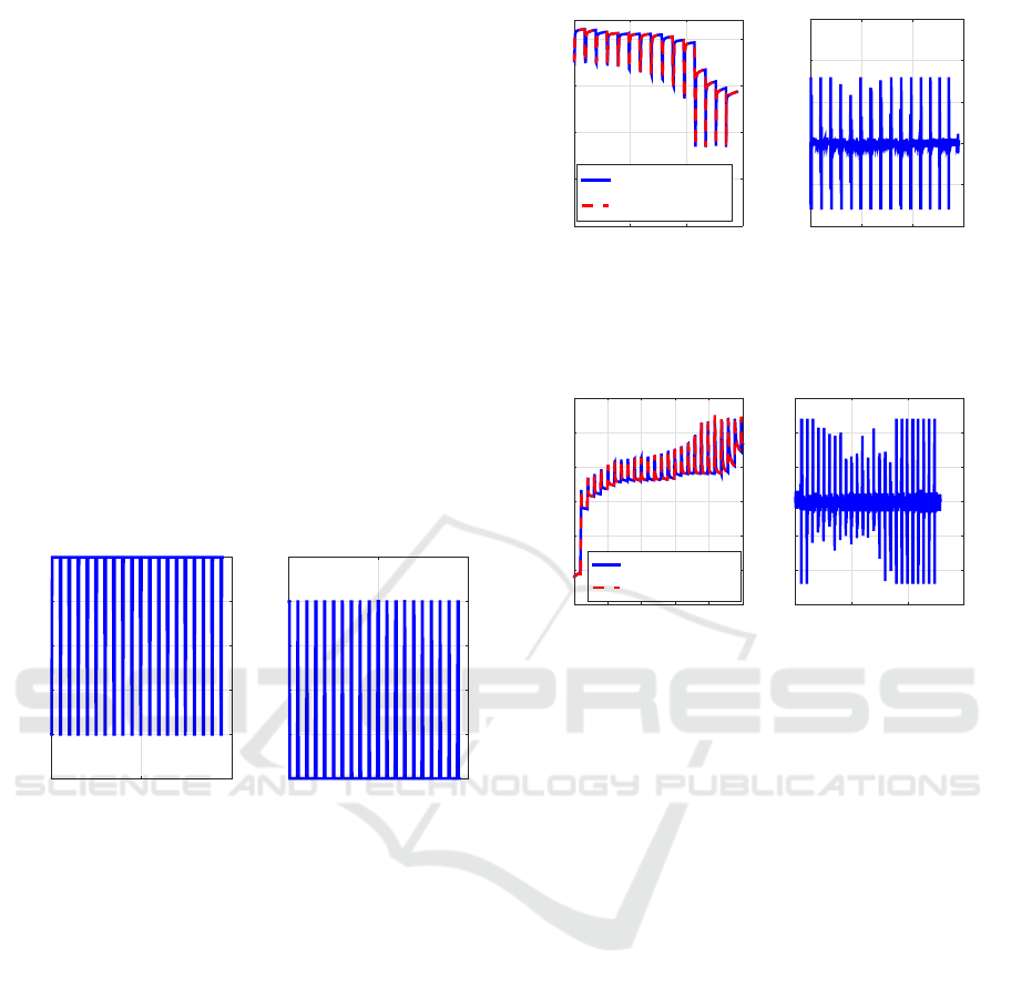
4.1 Simulation 1: BUSINOVA Battery
Model Validation
The objective of this section is to validate BUSI-
NOVA bus battery model through experimental tests
before implementing the diagnostic scheme. BUSI-
NOVA bus battery cell has rated capacity of 80 Ah
and nominal voltage of 4.1 V. The simulations have
been performed using the equivalent circuit-based
model provided in section 2.3. The proposed strategy
will validate in two cases using real data in high tem-
perature region and low temperature region for dis-
charging and charging. Figure 6 (left) shows the for
the discharging current profile. Figure 7 shows the
comparison of experimental and model output volt-
age and the voltage error for discharging at low tem-
perature −40
o
C. Figure 8 shows the comparison out-
put voltage and the voltage error for charging at thigh
temperature 40
o
C for the pulsating current given in
Figure 6 (right).
Time [Sec]
# 10
4
0 2 4
Discharging Current [A]
-100
-80
-60
-40
-20
0
Time [Sec]
# 10
4
0 2 4
Charging Current [A]
0
20
40
60
80
100
Figure 6: Battery current profile; (left) battery discharging
current profile; (right) battery charging current profile.
From Figures 7 and 8, one can observe that the pro-
posed model of Lithium-ion battery gives an accurate
modeling performance despite the system nonlineari-
ties, temperature and SOC variation. For the proposed
model, between 0% and 100% SOC, the standard de-
viation of voltagehas mean value error of ∼0.5 mV, or
∼0.2% of the operating voltage range at different tem-
perature and current (80A), which is less error com-
pared terminal voltage error of 1.5% (Sepasi et al.,
2014).
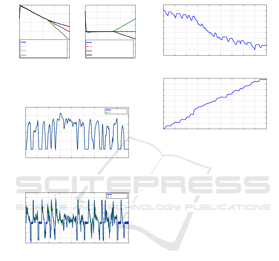
4.2 Simulation 2: Fault Detection and
its Effects on Battery SOC
Estimation
The objective of BMFFTC for the Lithium-ionbattery
presented in section 3.1.2 is to ensure that all signals
in the closed-loop battery system are bounded during
the battery faults. In this section, the effects of current
Time [Sec]
# 10
4
2 4 6
Battery Terminal Voltage [V]
2
2.5
3
3.5
4
Experimental Voltage
Model Output Voltage
Time [Sec]
# 10
4
0 2 4 6
Battery Terminal Voltage Error [V]
-0.01
-0.005
0
0.005
0.01
0.015
Figure 7: Comparison of experimental and model output
voltages and voltage error for discharge at −40
o
C and 80A;
(left) experimental and model output voltages; (right) volt-
age error.
Time [Sec]
# 10
4
1 2 3 4 5
Battery Terminal Voltage [V]
3
3.2
3.4
3.6
3.8
4
4.2
Experimental Voltage
Model Output Voltage
Time [Sec]
# 10
4
0 2 4 6
Battery Terminal Voltage Error [V]
# 10
-3
-6
-4
-2
0
2
4
6
Figure 8: Comparison of experimental and model output
voltages and voltage error for charge at 40
o
C and 80A; (left)
experimental and model output voltages; (right) voltage er-
ror.
or voltage sensor faults on the battery SOC estima-
tions and compensate its effect are investigated.The
advantage of the proposed strategy can detect and es-
timates time varying or/and constant fault. For the
testing purpose, it is required that sensor and/or ac-
tuator fail. The current or voltage sensor faults are
injected in the battery test bench. The initial value of
the fuzzy observer SOC state is 50%. The tested dis-
charging current profile is givenin Figure 9. Figure 10
(left) and (right) show the current sensor fault (+20
A bias fault) and voltage sensor fault (+0.1 V bias
fault) (solid lines) and their estimations (dashed lines)
based on the fuzzy observer, respectively. To pre-
vent the battery from over-discharge, the lower limit
of the battery SOC is taken as 10%. We are consid-
ered the ± 20 A bias sensor fault occur at the time
2406 sec. Figure 11 (left) plots the experimental SOC
estimation under the current sensor fault with FFTC
and without FFTC, while Figure 11 (right) shows the
SOC estimation errors. It can be found from Figure 11
(left) that the computed SOC in battery management
system (observer-estimated SOC) is around 20% at
the time 4812 sec when the current sensor has a +20
A bias fault. According to this result, the battery suf-
fering from over-discharge. Therefore, this will accel-
Robust Energy Management Strategy based on the Battery Fault Management for Hydraulic-electric Hybrid Vehicle
99

erate the battery aging and decrease the battery life.
For a −20 A bias fault, the estimated SOC will reach
to 10% and the battery cannot release the supposed
energy. Also with ±0.1 V bias fault at the time of
2406 sec, similar simulation results are obtained in
Figure 12 (left) and (right). The battery may be over-
discharged when the voltage sensor has a +0.1 V fault
as shown in Figure 12 (left). The estimation errors
are up to 22% with the voltage sensor faulty condi-
tion (cf. Figure12 (right)). The results show that the
battery may be over-discharged in the faulty sensor
cases. The simulation results demonstrate the effec-
tiveness of the proposed control approach. The pro-
posed control scheme can guarantee the stability of
the closed-loop battery system.
4.3 Simulation 3: Proposed Overall
Strategy Validation
The purpose of this section is to validate the pro-
posed overall control architecture for optimal energy
management. The proposed scheme is experimentally
tested under the UDDS (Urban DynamometerDriving
Schedule) and test conditions, including the recorded
faulty current or voltage data at room temperature.
Figures 13 and 14 depict the trajectories of bus veloc-
ity, and the torque under the UDDS drive cycle, re-
spectively. It is seen that the output speed and torque
of the vehicle is similar to the reference speed profile
and the torque demand of this drive cycle. The final
goal of the proposed strategy is to minimize the to-
tal energy consumption of the vehicle even during the
battery faults over the complete drive cycle, permit-
ting thus to increase the efficiency and the robustness
of the vehicle energy management strategy. The bat-
tery SOC for the studied driving cycle UDDS is given
in Figure 15. Figure 16 shows the total energy con-
sumption by the vehicle during the UDDS complete
cycle. From the simulation results, it is found that the
proposed strategy can be applied to the power assign-
ment for studied HHEV even if the future driving cy-
cle is unknownbecause it does not require beforehand
a-priori knowledge of the driving events.
From the simulation results, it can be seen that
without the reconfiguration mechanism, the battery
lost performance just after the sensor became faulty,
whereas for the same condition and using the pro-
posed FFTC scheme strategy, the battery remains sta-
ble in the presence of voltage sensor fault and current
actuator fault which demonstrates the effectiveness of
the proposed FFTC strategy.
In summary, it can be seen that the BUSINOVA
bus follows the trajectory of the reference input.
Thus, if driving cycles are changed, the control effect
Time [Sec]
0 500 1000 1500 2000 2500 3000 3500 4000 4500 5000
Current[A]
0
10
20
30
40
50
60
70
80
90
Figure 9: Battery discharging current profile.
Time [Sec]
0 2000 4000
Current Sensor Fault [A]
0
5
10
15
20
25
Fault
Estimation
Time [Sec]
0 2000 4000
Voltage Sensor Fault [V]
0
0.02
0.04
0.06
0.08
0.1
0.12
0.14
Fault
Estimation
Figure 10: Battery current and voltage sensor faults and
their estimations; (left) battery current sensor fault and its
estimation; (right) battery voltage sensor fault and its esti-
mation.
Time [Sec]
0 1000 2000 3000 4000
SOC [%]
-40
-20
0
20
40
60
80
Healthy: Experimental
Faulty Estimation With FFTC
Fault - 20A Estimation Without FFTC
Fault + 20A Estimation Without FFTC
Time [Sec]
0 1000 2000 3000 4000
SOC Error [%]
-25
-20
-15
-10
-5
0
5
10
15
20
Healthy: Experimental
Faulty Estimation With FFTC
Fault - 20A Estimation Without FFTC
Fault + 20A Estimation Without FFTC
Figure 11: Effects of current fault on battery SOC esti-
mation; (left) SOC estimation results in the current sen-
sor faulty conditions with FFTC and without FFTC; (right)
SOC estimation errors in the current sensor faulty condi-
tions with FFTC and without FFTC.
of the proposed strategy remains as accurate as the
results under UDDS cycle. In addition, the proposed
overall control architecture for optimal energy man-
agement is reliable even during current and/or voltage
sensor faults (cf. Section 4.2).
5 CONCLUSION
This paper presented a robust energy management
strategy, with battery faults detection and compensa-
tion for the studied hydraulic-electric hybrid vehicle.
In the first part, an appropriate design of systematic
ICINCO 2017 - 14th International Conference on Informatics in Control, Automation and Robotics
100
Time [Sec]
0 1000 2000 3000 4000
SOC [%]
-40
-20
0
20
40
60
80
Healthy: Experimental
Faulty Estimation With FFTC
Fault - 0.1V Estimation Without FFTC
Fault +0.1V Estimation Without FFTC
Time [Sec]
0 1000 2000 3000 4000
SOC Error [%]
-40
-30
-20
-10
0
10
20
30
40
Healthy: Experimental
Faulty Estimation With FFTC
Fault - 0.1V Estimation Without FFTC
Fault +0.1V Estimation Without FFTC
Figure 12: Effects of voltage fault on battery SOC esti-
mation; (left) SOC estimation results in the voltage sen-
sor faulty conditions with FFTC and without FFTC; (right)
SOC estimation errors in the voltage sensor faulty condi-
tions with FFTC and without FFTC.
Time[Sec]
0 100 200 300 400 500 600 700 800 900
Bus Speed[Km/h]
-5
0
5
10
15
20
25
Reference Speed
Propsed Strategy
Figure 13: Comparisons between reference speed and ac-
tual vehicle speed [Km/h] for proposed strategy over UDDS
cycle.
Time[Sec]
0 100 200 300 400 500 600 700 800 900
Wheel Required Torque[Nm]
-4000
-3000
-2000
-1000
0
1000
2000
3000
4000
5000
6000
Torque Demand
Actual Torque
Figure 14: Comparisons between reference torque and ac-
tual vehicle torque [Nm] for proposed strategy over UDDS
cycle.
BMFFTC (Battery Management Fuzzy Fault Tolerant
Controller) scheme is proposed to estimate and com-
pensate the battery faults. Some sufficient conditions
for robust stabilization of the TS fuzzy model were
derivedfor a Lithium-ion battery and were formulated
in an LMI (Linear Matrix Inequalities) format. The
second part of the paper has been focused on minimiz-
ing total energy consumption and thereby on increas-
ing the total distance traversed between refueling of
the studied hybrid vehicle. The proposed method has
been implemented using real time power management
strategy, named Robust Energy Management Strategy
(REMS). This proposed strategy consists of two con-
trol levels. The highest one (the second level) has
Time [Sec]
0 100 200 300 400 500 600 700 800 900
SOC [%]
94.2
94.3
94.4
94.5
94.6
94.7
94.8
94.9
95
95.1
Figure 15: SOC for the proposed strategy over UDDS cycle.
Time [Sec]
0 100 200 300 400 500 600 700 800 900
Total Consumed Energy [KJ]
0
1000
2000
3000
4000
5000
6000
7000
8000
9000
Figure 16: Total energy consumed by the vehicle [KJ] for
proposed strategy over UDDS cycle.
been developed using fuzzy strategy and fuzzy ob-
server in order: to manage all of the possible bus oper-
ation modes, generates SOC set point for second level
and compensate the battery faults. At the first level,
an energy management strategy has been developed
for power splitting which decides the optimal com-
bination of power sharing (between different energy
sources) to minimize the total bus energy consump-
tion while maximizing the overall vehicle efficiency.
The obtained results confirm that, using the proposed
approach: (i) the strategy can be easily implemented
in real time because it does not depend on prior in-
formation about future driving conditions; (ii) battery
faults could be accurately detected and compensated
to minimize its aging effects; (iii) minimize total en-
ergy consumption; (iv) mean and the standard devi-
ation of the membership function of the fuzzy logic
controller are optimized based on neural-network. It
is planned in near future to implement the overallpro-
posed control strategy on the actual BUSINOVA plat-
form.
ACKNOWLEDGEMENTS
This project is supported by the ADEME (Agence
De l’Environnement et de la Matrise de l’Energie)
for the National French program Investissement
d’Avenir, through BUSINOVA Evolution project,
(see http://www.businova.com/en).
Robust Energy Management Strategy based on the Battery Fault Management for Hydraulic-electric Hybrid Vehicle
101

REFERENCES
Abdrakhmanov, R. and Adouane, L. (2017). Efficient acc
with stopgo maneuvers for hybrid vehicle with on-
line sub-optimal energy management. In 11th In-
ternational Workshop on Robot Motion and Control,
Wasowo-Poland, 3-5 July. RoMoCo’17.
Edwards, C. (2006). A comparison of sliding mode and
unknown input observers for fault reconstruction. In
vol.12, no.3, pp. 245-260. European journal of control.
Gupta, V. (2015). Optimization trilogy for energy manage-
ment in parallel hybrid electric vehicles. In vol. 17,
pp.1-12. HCTL Open International Journal of Tech-
nology Innovations and Research (IJTIR).
Hamed, B. and Almobaied, M. (2011). Fuzzy pid con-
trollers using fpga technique for real time dc motor
speed control. In vol. 2, pp. 233-240. Intelligent Con-
trol and Automation.
Hou, C., Ouyang, M., Xu, L., and Wangi, H. (2014). Ap-
proximate pontryagin’s minimum principle applied to
the energy management of plug-in hybrid electric ve-
hicles. In vol. 115, pp. 174-189. Applied Energy.
Kamal, E., Adouane, L., Abdrakhmanov, R., and Oud-
dah, N. (2017a). Hierarchical and adaptive neuro-
fuzzy control for intelligent energy management in
hybrid electric vehicles. In World Congress, 9-14 July,
Toulouse-France. IFAC.
Kamal, E., Adouane, L., Aitouche, A., and Mohammed, W.
(2017b). Robust power management control for stand-
alone hybrid power generation system. In vol. 783, pp.
12-25. Journal of Physics: Conference Series.
Kamal, E., Aitouche, A., Ghorbani, R., and Bayart, M.
(2012). Robust fuzzy fault tolerant control of wind
energy conversion systems subject to sensor faults. In
Transactions on Sustainable Energy, vol. 3, no 2, pp.
231-241. IEEE.
Lu, L., Han, X., Li, J., Hua, J., and Ouyang, M. (2013). A
review on the key issues for lithium-ion battery man-
agement in electric vehicles. In vol. 226, pp. 272-288.
J. Power Sources.
Maleki, H. and Howard, J. N. (2006). Effects of overdis-
charge on performance and thermal stability of a li-
ion cell. In vol. 160, no. 2, pp. 1395-402. J. Power
Sources.
Martnez, C. M., Hu, X., Cao, D., Velenis, E., Gao, B., and
Weller, M. (2016). Energy management in plug-in
hybrid electric vehicles: Recent progress and a con-
nected vehicles perspective. In Transactions on Ve-
hicular Technology, vol. PP, no.99, pp.1-16. IEEE.
Panday, A. and Bansal, H. O. (2016). Energy management
strategy implementation for hybrid electric vehicles
using genetic algorithm tuned pontryagin’s minimum
principle controller. In vol. 2016, pp.1-13. Interna-
tional Journal of Vehicular Technology.
Plett, G. L. (2004). Extended kalman filtering for bat-
tery management systems of lipb-based hev battery
packspart 3. state and parameter estimation. In vol.
134, pp. 277-29. J. Power Sources.
Sepasi, S., Ghorbani, R., and Liaw, B. Y. (2014). A
novel on-board state-of-charge estimation method for
aged lithium-ion batteries based on model adaptive
extended kalman filter. In vol. 245, pp.337-344. J.
Power Sources.
Striebel, K., Shim, J., Sierra, A., Yang, H., Song, X.,
Kostecki, R., and McCarthy, K. (2005). The develop-
ment of low cost lifepo4-based high power lithium-ion
batteries. In vol.146, pp. 33-38. J. Power Sources.
Tate, E., Grizzle, J., and Peng, H. (2010). Sp-sdp for fuel
consumption and tailpipe emissions minimization in
an evt hybrid. In Transactions on Control Systems
Technology,vol. 18, no. 3, pp. 673-687. IEEE.
Tulpule, P., Marano, V., and Rizzoni, G. (2010). Energy
managemernt for plug-in hybrid electric vehicles us-
ing equivalent consumption minimisation strategy. In
vol. 2 , no.4, pp. 329-350. Int J. Electric and Hybrid
Vehicles.
Xing, Y., Ma, E. W. M., Tsui, K.-L., and Pecht, M. (2013).
An ensemble model for predicting the remaining use-
ful performance of lithium-ion batteries. In vol. 53,
no. 6, pp. 811-820. Microelectronics Reliability.
APPENDIX
This appendix gives the proof for the Theorem 1. In
order to carry out the analysis for BMFTC, the closed-
loop fuzzy system should be obtained first by estab-
lishing the conditions for the asymptotic convergence
of the observers. The fuzzy control system of the state
and the errors can be obtained. Substituting (13) into
(7) and (8), we obtain the dynamics of the closed loop
system and the state estimation error.
Therfore, from (9), (10), (11) and (12), we obtain
˙
X(t) =
∑
p
i=1
∑
p
j=1
µ
i
µ
j
[(
¯
A
i
+
¯
B
i
G
j
)X(t) +
¯
E
i
f(t)]
−
∑
p
i=1
∑
p
j=1
µ
i
µ
j
¯
B
i
G
j
e
x
(t) −
∑
p
i=1
µ
j
¯
B
i
E
i
ˆ
f(t)]
(20)
Let
˜
f(t) = f(t) −
ˆ
f(t) (21)
From(20) and (21), a TS fuzzy closed-loop can be
observed:
˙
X(t) =
∑
p
i=1
∑
p
j=1
µ
i
µ
j
[(
¯
A
i
+
¯
B
i
G
j
)X(t)
−
¯
B
i
G
j
e
x
(t) +
¯
E
i
˜
f(t)]
(22)
Then taking the derivative of e
x
(t) in (9) and substitut-
ing from (7), (8) and (21), the following is obtained:
˙e
x
(t) =
p
∑
i=1
[(
¯
A
i
− K
i
¯
C
i
)e
x
(t) +
¯
E
i
˜
f(t)] (23)
The derivative of
˜
f(t) in (21) can be written as,
˙
˜
f(t) =
˙
f(t) −
˙
ˆ
f(t) =
˙
f(t) −
∑
p
i=1
µ
i
L
i
¯
C
i
(
∑
p
i=1
[(
¯
A
i
− K
i
¯
C
i
+ I)e
x
(t) +
¯
E
i
˜
f(t)])
(24)
ICINCO 2017 - 14th International Conference on Informatics in Control, Automation and Robotics
102

Combining (22), (23) and (24) yields the following
augmented fuzzy system.
˙
˜
X(t) =
p
∑
i=1
µ
i
µ
j
[
˜
H
ij
˜
X(t) +
˜
E
i
F(t)]
˜
Y(t) =
p
∑
i=1
µ
i
˜
C
i
˜
X(t)
(25)
with
˜
X(t) =
X(t)
e
x
(t)
˜
f(t)
, F(t) =
0
0
˙
f(t)
,
˜
H
ij
=
(
¯
A
i
+
¯
B
i
G
j
) H
1ij
0
2x1
H
2ij
−
¯
K
i
¯
C
1i
,
¯
K
i
=
K
i
L
i
,
H
1ij
=
−
¯
B
i
G
j
¯
E
i
,
˜
C
i
=
¯
C
i
0
T
,
˜
E
i
=
0 0
0 I
,
H
2ij
=
¯
A
i
¯
E
i
−L
i
¯
C
i
(
¯
A
i
− K
i
¯
C
i
) −L
i
¯
C
i
¯
E
i
.
Let us consider the following quadratic Lyapunov
candidate function V(t):
V(t) =
˜
X(t)
T
P
˜
X(t) (26)
where P is common positive definite matrix. The
problem of robust state and fault estimation is to find
the gains G
j
, K
i
and L
i
of the controller and the ob-
servers to ensure an asymptotic convergence of X(t)
toward zero when F(t) = 0. This problem is reduced
to find P verifying V(t) < 0, i.e.,
˙
˜
X(t) =
p
∑
i=1
µ
i
˜
H
i
˜
X(t) (27)
The derivative time of V(t) is given by
˙
V(t) =
1
2
˙
˜
X(t)
T
P
˜
X(t) +
1
2
˜
X(t)
T
P
˙
˜
X(t) (28)
By substituting (27) into (28), one obtain
˙
V(t) =
1
2
˜
X(t)
T
p
∑
i=1
µ
i
(
˜
H
T
i
P+ P
˜
H
i
˜
X)(t) (29)
From (29), the derivative time of (26) is uniformly
negative if the following inequality is satisfied
P
˜
H
ij
+
˜
H
ij
T
P < 0 ∀i, j (30)
Let P =
P
1
0
0 P
2
, Therefore, the inequality (30) will
be rewritten as:
P
1
(A
i
−B
i
G
j
) + (A
i
−B
i
G
j
)
T
P
1
< 0 ∀i, j (31)
P
2
(H
bi
−
¯
K
i
¯
C
i
) + (H
bi
−
¯
K
i
¯
C
i
)
T
P
2
< 0 ∀i, j (32)
By multiplying(31) from left and right by O = P
−1
1
,
and applying the change of variables O = P
−1
1
, W
j
=
G
j
O, D
i
= P
2
¯
K
i
, LMIs (14) and (15) are obtained.
Robust Energy Management Strategy based on the Battery Fault Management for Hydraulic-electric Hybrid Vehicle
103
