
Blind Decision Feedback Equalizer for Holographic Versatile Disc
Kyuhwan Kim, Seung Hun Kim, Gyogwon Koo, Min Seok Seo and Sang Woo Kim
Department of Electrical Engineering, Pohang University of Science and Technology, 77 Cheongam-Ro, Pohang, Korea
Keywords:
Holographic Data Storage (HDS), Holographic Versatile Disc (HVD), European Standard, Blind Equalizer,
Decision Feedback Equalizer (DFE).
Abstract:
As the amount of data increases, holographic data storage (HDS) is considered as a next generation storage
medium. Since HDS uses two-dimensional (2D) data, it causes intersymbol interference (ISI) between adja-
cent pixels not only in the horizontal direction but also in the vertical direction. Thus, studies have been car-
ried out to reduce such 2D ISI, and especially many researches using the partial response maximum likelihood
(PRML) method have been carried out. These PRML methods have good bit-error-rate (BER) performance,
but also have various disadvantages. Therefore, we propose a simple blind decision feedback equalizer (blind
DFE) that does not use soft output Viterbi algorithm (SOVA) for application to European standard holographic
versatile disc (HVD). First, we propose a blind equalizer using simle theshold method to get information that
the equalizer can refer to. In order to make it work well in any environment, the threshold value is adaptively
determined using the statistical characteristics of the received image. And, in order to reduce errors due to the
data that cannot be distinguished only by the blind equalizer, we add a decision feedback loop after the blind
equalizer. Finally, various simulations were conducted to confirm the performance of blind DFE for HVD.
1 INTRODUCTION
As the amount of data increases, holographic data
storage (HDS) is considered as a next generation stor-
age medium. Unlike other optical disks, HDS uses
holographic images to store two-dimensional (2D)
data pages on a holographic versatile disc (HVD). The
European standard for HVD was proposed in 2007
(ECMA, 2007a; ECMA, 2007b).
Since HDS uses 2D data, it causes intersymbol in-
terference (ISI) between adjacent pixels not only in
the horizontal direction but also in the vertical direc-
tion. This 2D ISI has a lot of impact on the perfor-
mance of HDS, and many studies are going on to re-
duce it. The most studied methods to reduce 2D ISI
in HDS is the partial response maximum likelihood
(PRML) method using soft output Viterbi algorithm
(SOVA) (Kim and Lee, 2009; Koo et al., 2012; Koo
et al., 2013; Koo et al., 2014). These PRML methods
have good bit-error-rate (BER) performance, but also
have various disadvantages.
There are a few problems that arise from the use
of SOVA. In order to improve BER performance, the
PRML methods use SOVA (Hagenauer and Hoeher,
1989) based on Viterbi decoder (Viterbi, 1967) as
maximum likelihood (ML) method. The first problem
is that this Viterbi algorithm requires a lot of com-
putation because all Viterbi paths need to be investi-
gated. Especially, since the Viterbi algorithm needs
to be applied in two dimensions in order to apply it to
the HDS, much more computational complexity is re-
quired than the Viterbi decoder used in the field of
communications. In (Koo et al., 2012; Koo et al.,
2013; Koo et al., 2014), many studies have been done
to reduce the computational complexity of 2D SOVA
while improving performance, but it is still a problem
to have a large amount of computation as SOVA is
used.
The second problem that arises from using 2D
SOVA is that it does not work with European standard
code. In the European standard, in order to reduce the
error rate of a symbol, if a certain pixel has a value of
1, the adjacent pixels can not have a value of 1 in a 4-
by-4 (4 ×4) symbol. That is, only three pixels of the
sixteen pixels have a value of one and the remaining
pixels have a zero value. However, the Viterbi de-
coder basically assumes that all messages are equally
probable (Viterbi, 1967). Therefore, if the European
standard code is used, SOVA will not work properly
because the probability of 0 and 1 is different.
The last problem with using the PRML method is
that a training sequence is necessary. Using training
468
Kim, K., Kim, S., Koo, G., Seo, M. and Kim, S.
Blind Decision Feedback Equalizer for Holographic Versatile Disc.
DOI: 10.5220/0006425004680473
In Proceedings of the 14th International Conference on Informatics in Control, Automation and Robotics (ICINCO 2017) - Volume 1, pages 468-473
ISBN: 978-989-758-263-9
Copyright © 2017 by SCITEPRESS – Science and Technology Publications, Lda. All rights reserved
sequences can not make use of that much data, and
because the equlizer is trained to a specific environ-
ment, performance degrades when the environment
changes. Therefore, in order to increase the data rate
and robustness to various environments, blind equal-
izer that do not require training sequences have to be
developed and used as in the field of communications.
However, since the PRML method uses a training
equalizer that requires a training sequence, the data
rate is lowered, and when the channel environment is
changed, the performance may be degraded.
Therefore, we propose a simple blind equalizer
that does not use SOVA for application to European
standard HVD. The remaining paper is organized as
follows. Section 2 explains the background HVD
channel model, and a simple form of blind eualizer
is proposed in Section 3. In order to compensate
for the performance of the blind equalizer, Section 4
describes a decision feedback equalizer (DFE), and
several simulation results will be represented in Sec-
tion 5. Finally, we will conclude and discuss the re-
sults in Section 6.
2 HVD CHANNEL MODEL
In HVD, using spatial light modulator (SLM), the in-
put data page, d[x, y], is encoded to the holographic
medium along the reference laser beam (Vadde and
Kumar, 1999). When reading the stored data page,
the data page is displayed in the form of a hologram
using the same reference beam and read by a charge-
coupled device (CCD). In this process, the data page
suffers blur effect (2D ISI), noise and misalignment.
In this channel environment, blur effect and misalign-
ment are modelled as point spread function (PSF) and
noise is modelled as additive white Gaussian noise
(AWGN) (Vadde and Kumar, 1999; Keskinoz and Ku-
mar, 2000).
The continuous PSF is expressed by
h(x, y) =
A
2
σ
2
b
sinc
2
x −m
x
σ
b
,
y −m
y
σ
b
(1)
where A is the signal amplifier, σ
b
is the blur grade,
and m
x
and m
y
are the misalignments in the horizontal
and vertical directions, respectively. In this paper A is
set to
√
2. And the discrete PSF is given by
h[x, y] =
Z
y+
α
2
y−
α
2
Z
x+
α
2
x−
α
2
h(x
0
, y
0
)dx
0
dy
0
(2)
where α(0 < α ≤ 1) is a linear fill factor of the CCD
pixels. In this paper, we used 1 as α.
As mentioned earlier, channel noise n[x, y] is mod-
elled as AWGN. And the channel signal-to-noise ratio
(SNR) is defined as follows:
SNR = 10log
10
1
σ
2
w
(3)
where σ
2
w
is the AWGN power.
Therefore, the image detected by the CCD sensor
r[x , y] is obtained as follows:
r[x , y] = d[x,y] ⊗h[x, y] + n[x, y] (4)
where ⊗is a 2D convolution operator. Figure 1 shows
the block diagram of this channel model.
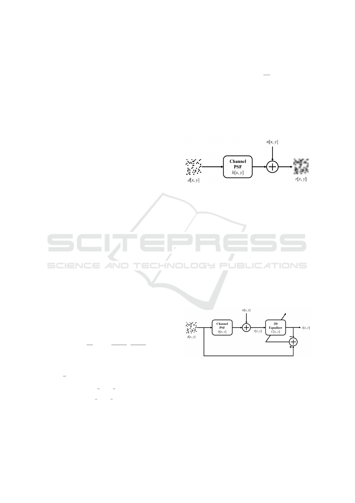
Figure 1: Block diagram of channel model.
3 BLIND EQUALIZER
The image obtained by the CCD sensor passes
through a 2D equalizer to eliminate the 2D ISI, and
the equalizer output z[x, y] is as follows:
z[x, y] = r[x, y]⊗C[x, y] (5)
where C[x, y] is the array of equalizer coefficient
which are adaptively updated using the error.
Figure 2 represents the structure of a conventional
2D training equalizer. When the training sequence
is used in the PRML method, the sequence passes
through partial response (PR) target to perform en-
coding for the ML scheme.
Figure 2: Structure of conventional 2D equalizer.
As mentioned earlier, the use of training equalizer re-
duces the data rate because it requires a training se-
quence, and because it is trained to a specific environ-
ment, it becomes vulnerable to various environmental
changes. Thus, it is necessary to develop and use a
blind equalizer. However, the blind equalizers used in
the field of communications, such as constant modu-
lus algorithm (CMA) (Sato, 1975) and multi-modulus
algorithm (Yang et al., 2002), are not applicable to
Blind Decision Feedback Equalizer for Holographic Versatile Disc
469
HVD. This is because the blind equalizers in the field
of communications match the norm of complex sym-
bol to a specific value, but the data of HVD is com-
posed of binary pixel arrays. Therefore, we propose a
simple blind equalizer for HVD which has a different
mechanism from that in the field of communications.
Although it is not possible to match the equalizer
output to a specific value as in the field of communi-
cations, some information from the received image is
necessary to update the equalizer. So we used simple
threshold method to get information that the equalizer
can refer to. Figure 3 depicts the structure of proposed
blind equalizer.
Figure 3: Structure of proposed blind equalizer.
To make the threshold method work well, it is impor-
tant to set the threshold value well. Thus, in order
to make it work well in any environment, the thresh-
old value is adaptively determined using the statistical
characteristics of the received image, not simply using
the mean value.
Figure 4 shows the statistical characteristics of the
received images when using the European standard.
Figure 4 (a) represents the histogram of total received
image, and dividing this into a 0-bit histogram and 1-
bit histogram, the results graph is shown in Figure 4
(b). From this graph, we can determine which value
should be set to the threshold value to distinguish be-
tween 0 and 1 well. (In this case, the pixel value of
0.5137 is set as the threshold value because it can
distinguish between 0 and 1 well.) Figure 4 (c) de-
picts accumulative histogram of total received image.
In the European standard, since there are 13 zeros in
one symbol, it can be seen that 0 and 1 can be dis-
tinguished by setting the pixel value having the value
corresponding to 13/16 in the accumulative histogram
as the threshold value. In this case, the pixel value
of 0.5333 having the accumulative histogram value
of 0.8118 closest to 0.8125 corresponding to 13/16
in the accumulative histogram is set as the threshold
value. This threshold value is good enough to dis-
tinguish between 0 and 1 in the present environment.
Using this scheme, it is possible to find the optimal
threshold value to distinguish between 0 and 1, even
if the statistical characteristics of the received image
change due to environmental changes. And the out-
put from the proposed equalizer is finally determined
to be 0 or 1.
(a)
(b)
(c)
Figure 4: (a) Histogram of total received image, (b) his-
togram of zero bit and one bit , (c) accumulative histogram
of total received image.
ICINCO 2017 - 14th International Conference on Informatics in Control, Automation and Robotics
470

4 BLIND DECISION FEEDBACK
EQUALIZER
We have previously proposed a simple and efficient
blind equalizer for HVD. However, as shown in Fig-
ure 4 (b), there is a little probability of error occur-
rence when only the blind equalizer using this thresh-
old method is used. Thus, in order to reduce errors
due to the data that cannot be distinguished only by
the blind equalizer, we propose a blind decision feed-
back equalizer (blind DFE) by adding a decision feed-
back loop after the blind equalizer.
The DFE has also been proposed in the field of
communications (George et al., 1971). Assuming that
previously determined values are correct, the DFE
basically attempts to obtain a more accurate output
by eliminating the influence of previously determined
values on later values, i.e. ISI. Figure 5 shows the
structure of the DFE. As shown in the figure, the DFE
in the field of communications updates both feedfor-
ward filter (FFF), which acts as the equalizer, and
feedback filter (FBF) in the feedback loop using the
difference between
˜
d[x] and d[x].
Figure 5: Structure of DFE.
This DFE has the advantage of obtaining accurate out-
put on the assumption that the decisions are correct,
but it is difficult to apply to HVD. In the field of com-
munications, DFE effectively eliminates ISI by using
1D FBF for 1D FFF. However, in HVD, when using
2D FBF for 2D equalizer, it is ambiguous to accu-
rately define and use the influence of the previously
determined value. Thus, a simple form of DFE with-
out FBF for HDS has been proposed (Marrow and
Wolf, 2003). This simple DFE uses decision feedback
in the row or column direction instead of using the 2D
FBF. It also implies that when the detection process
proceeds in the lower right direction, the pixel to be
detected is much affected by the upper pixel and the
left pixel.
Considering these characteristics, we propose a
blind DFE for HVD. Figure 6 represents the structure
of the blind DFE. In the feedback loop, z
−1
h
and z
−1
v
are unit delay operator in the horizontal and vertical
directions, respectively, and K is the scalar multiply-
ing operator.
This blind DFE can be divided into two parts. The
front part is the blind equalizer part and the rear part
Figure 6: Structure of proposed blind DFE.
is the decision feedback part. As explained in the pre-
vious section, in the blind equalizer part, the equalizer
is updated by comparing the reference data created by
the threshold method with the output of the equalizer,
not with the result obtained by subtracting the deci-
sion feedback like the DFE in the field of communi-
cations. In the decision feedback part, the ISI due to
the already determined symbol is removed by feed-
ing back the value obtained by multiplying the deter-
mined upper or left pixel values and an appropriate
scalar.
In contrast to the conventional DFE, in which
the equalizer part and the decision feedback part are
coupled together to improve the performance of the
equalizer, the blind DFE for HVD is divided into
the equalizer part and the decision feedback part,
and each part performs their respective roles. In the
equalizer part, even if there is some error due to ISI,
the data page is roughly restored using the threshold
method. In the latter part of the decision feedback,
it helps to get more accurate results before the final
decision by eliminating the errors due to ISI, that are
missed by the blind equalizer.
5 SIMULATION RESULTS
5.1 Simulation Setting
Various BER simulations were conducted to confirm
the performance of blind DFE for HVD, because the
data rate and robustness increase with increasing BER
in the HDS. In all simulations performed in this paper,
we simulated 256 ×256 data pages which have simi-
lar size to the European standard. And all data pages
are encoded according to European standard codes
(ECMA, 2007a; ECMA, 2007b). The HVD channel
model is assumed to be a discrete PSF of size 5 ×5,
and thus an equalizer with a 5 ×5 size coefficient is
used. The step size used for updating the equalizer is
set to a value of 0.01. The value of scalar K multi-
plied when the decision feedback was used as 0.1 to
reflect the ISI phenomenon of HVD. All BER values
resulting from the simulation are the ensemble aver-
ages of simulated results of 100 data pages in each
environment.
Blind Decision Feedback Equalizer for Holographic Versatile Disc
471
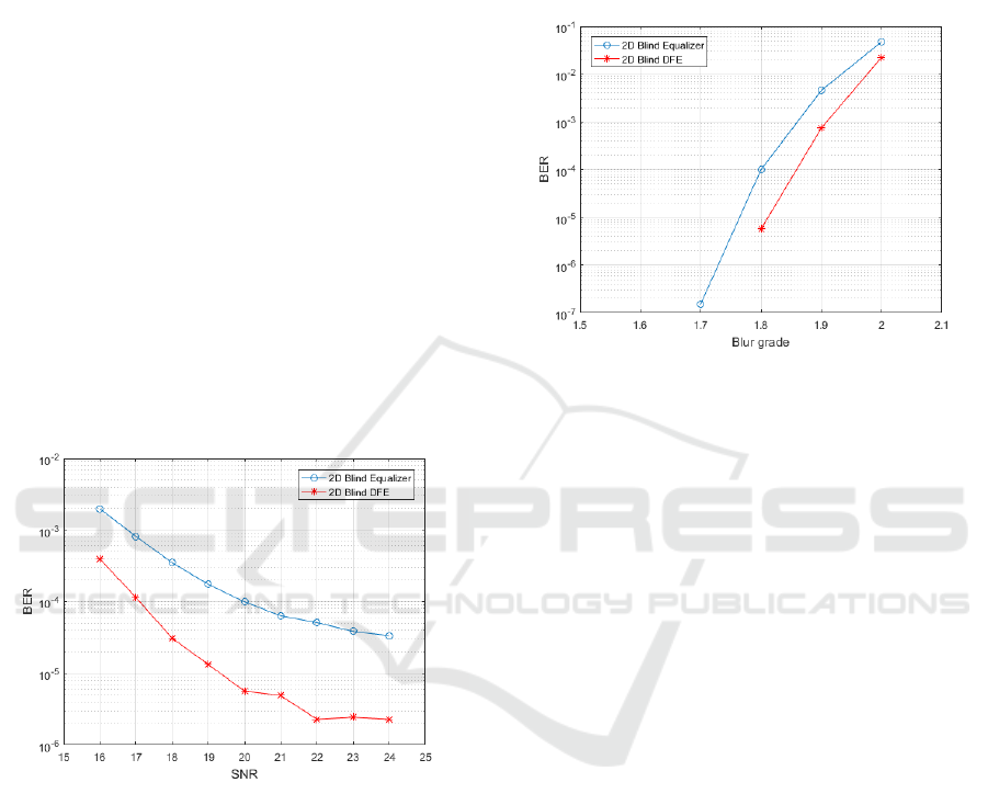
5.2 SNR Simulation
First, we simulated the performance of the blind
equalizer for noise. Simulations were performed for
various SNRs in an environment with a blur grade of
1.8 and a misalignment of 5 % in the channel model.
Figure 7 shows the BER performance to the noise. As
can be easily expected, when SNR becomes larger,
BER becomes smaller, and the blind DFE has better
performance than the blind equalizer. But, the influ-
ence of the SNR on the HVD channel model is rela-
tively small, so that the BER variation due to the SNR
change is not so severe. In the case of the blind equal-
izer, when the SNR is 20 or more, the BER is smaller
than 10
−3
, so the data page can be perfectly recon-
structed using an error correction code (ECC). On the
other hand, when the SNR is less than 20, the BER is
larger than 10
−3
, so there is a possibility that the re-
construction rate will fall. However, in the case of the
blind DFE, the BER is much smaller than the blind
equalizer. And, as long as the SNR is not too small,
the BER is less than 10
−3
, which makes it possible to
restore the data page completely using ECC.
Figure 7: BER performance to the noise.
5.3 Blur Grade Simulation
Secondly, we simulated the performance of a blind
equalizer for blur grade. Simulations were performed
for varying blur grade in an environment with a SNR
of 20 dB and a misalignment of 5 %. Figure 8 rep-
resents the BER performance to the blur grade. As
can be easily expected, the BER increases as the blur
grade increases, and the performance of the blind
DFE is better than the blind equalizer. Also, since
the blur grade has a large influence on the HVD chan-
nel model, it can be seen that the change of blur grade
make the BER change a lot. Thus, if the blur grade
becomes smaller than 1.7 for the blind equalizer and
1.8 for the blind DFE, the equalizer will restore the
data page completely and the number of errors will be
zero. Conversely, if the blur grade increases to about
2, the BER may become larger than 10
−3
, which may
result in a decrease in the reconstruction rate of the
data page.
Figure 8: BER performance to the blur grade.
5.4 Misalignment Simulation
Finally, we simulated the performance of a blind
equalizer for misalignment. Simulations were per-
formed for various misalignments in an environment
with a SNR of 20 dB and a blur grade of 1.8. Fig-
ure 9 depicts the BER performance to the misalign-
ment. Also, if the misalignment increases, the BER
increases too, and the blind DFE has better perfor-
mance than the blind equalizer. Similar to the blur
grade, larger misalignment can have a catastrophic ef-
fect on the performance of the blind equalizer, but
there is little chance of misalignment greater than
10 % in the HVD due to sync patterns. Thus, un-
der the assumption that the misalignment is less than
10 %, it is not easy to have a fatal impact on the BER
performance.
6 CONCLUSIONS
In this paper, we propose the blind DFE for HVD. The
development of the blind DFE has proceeded in two
stages.
The first approach was to develop a blind equal-
izer for HVD. Because HVD data is structurally diffi-
cult to match the norm value of a symbol to a specific
value, as in the field of communications, it was nec-
essary to design a blind equalizer in a different way
from the field of communications. However, since it
is necessary to have information that can be referred
ICINCO 2017 - 14th International Conference on Informatics in Control, Automation and Robotics
472
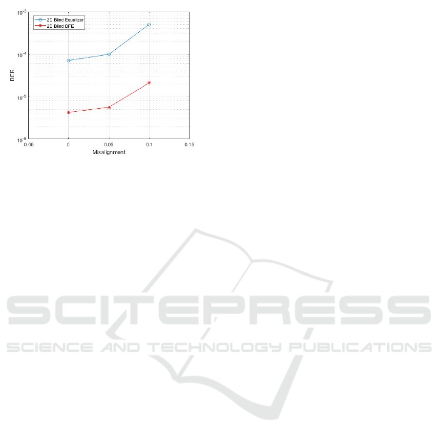
Figure 9: BER performance to the misalignment.
to by the equalizer, a simple threshold method is used
to generate information to be referred to by the equal-
izer, and the equalizer is updated using the informa-
tion. In addition, the threshold value is determined by
analysing the statistical characteristics of the received
image, rather than simply using the average value, and
thus the same performance can be maintained even
when the environment is changed.
The second step is to add a decision feedback loop
behind the equalizer in order to compensate for the
blind equalizer that may cause errors. In the field of
communications, the DFE updated both the equalizer,
which act as FFF, and the FBF by comparing the value
obtained by subtracting the decision feedback from
the equalizer output to the training sequence. How-
ever, since it is structurally difficult to implement a 2D
FBF in HVD, a decision feedback loop is constructed
by multiplying the upper and left pixel values, which
have the greatest effect on the current pixel, by an ap-
propriate scalar value.
Although the blind DFE which consists of two
parts does not perform the entire equalization process
at the same time as the DFE in the field of communi-
cations, the data page is roughly restored in the equal-
izer part even if there is a slight error caused by the
ISI, and the effects of errors due to ISI are eliminated
in the decision feedback part. As a result, the two
parts combine to create the blind DFE for HVD, that
effectively removes ISI and performs well.
ACKNOWLEDGEMENTS
This research was supported by Basic Science
Research Program through the National Research
Foundation of Korea (NRF) funded by the Min-
istry of Education, Science and Technology (NRF-
2015R1D1A1A09059377).
REFERENCES
ECMA (2007a). Information Interchange on Holographic
Versatile Disc (HVD) Recordable Cartridges Capac-
ity: 200 Gbytes per Cartridge. ECMA International,
Geneva, 1st edition.
ECMA (2007b). Information Interchange on Read-Only
Memory Holographic Versatile Disc (HVD-ROM)
Capacity: 100 Gbytes per disk. ECMA International,
Geneva, 1st edition.
George, D. A., Bowen, R. R., and Storey, J. R. (1971). An
adaptive decision feedback equalizer. IEEE Transac-
tions on Communication Technology, COM-19.
Hagenauer, J. and Hoeher, P. (1989). A viterbi algorithm
with soft-decision outputs and its applications. In
Global Telecommunications Conference and Exhibi-
tion ’Communications Technology for the 1990s and
Beyond’ (GLOBECOM). IEEE.
Keskinoz, M. and Kumar, B. V. K. V. (2000). Efficient mod-
eling of volume holographic storage channels (vhsc).
In Optical Data Storage. IEEE.
Kim, J. and Lee, J. (2009). Partial response maximum like-
lihood detections using two-dimensional soft output
viterbi algorithm with two-dimensional equalizer for
holographic data storage. Japanese Journal of Applied
Physics, 48.
Koo, K., Kim, S., Jeong, J., and Kim, S. (2013). Two-
dimensional soft output viterbi algorithm with a vari-
able reliability factor for holographic data storage.
Japanese Journal of Applied Physics, 52.
Koo, K., Kim, S., Jeong, J., and Kim, S. (2014). Data page
reconstruction method based on two-dimensional soft
output viterbi algorithm with self reference for holo-
graphic data storage. Optical Review, 21.
Koo, K., Kim, S., and Kim, S. (2012). Modified two-
dimensional soft output viterbi algorithm with two-
dimensional partial response target for holographic
data storage. Japanese Journal of Applied Physics,
51.
Marrow, M. and Wolf, J. K. (2003). Iterative detection of
2-dimensional isi channels. In Information Theory
Workshop. IEEE.
Sato, Y. (1975). A method of self-recovering equalization
for multilevel amplitude-modulation systems. IEEE
Transactions on Communications, 23.
Vadde, V. and Kumar, B. V. K. V. (1999). Channel model-
ing and estimation for intrapage equalization in pixel-
matched volume holographic data storage. Applied
Optics, 38.
Viterbi, A. J. (1967). Error bounds for convolutional codes
and an asymptotically optimum decoding algorithm.
IEEE Transactions on Information Theory, IT-13.
Yang, J., Werner, J. J., and Dumont, G. A. (2002). The
multimodulus blind equalization and its generalized
algorithms. IEEE Journal on Selected Areas in Com-
munications, 20.
Blind Decision Feedback Equalizer for Holographic Versatile Disc
473
