
Multi-robot Control Architecture for Hospital Delivery Service in
Unstable Network Environment
Seohyun Jeon and Jaeyeon Lee
Human Machine Interaction Research Group,
Electronics and Telecommunications Research Institute (ETRI), Daejeon, Korea
Keywords:
Hospital, Logistics, Delivery, Robot, Unstable, Network.
Abstract:
This paper describes the problem about controlling multiple robots in a real world when the network con-
nection is unstable. Robots are deployed at the hospital for delivery service. Robots navigate autonomously
through the hospital-wide hallway while delivering items from point to point. The delivery task is assigned
and sent to the robot by the server via wireless network. To increase the performance of using fleet of robots,
online task assignment and fleet optimization is required. However, the robots are frequently disconnected
with the network since the robot continuously moves and the mission area covers multiple floors. The online
communication cannot be guaranteed at all times. Therefore, this paper proposes a control architecture to cope
with such unstable network connectivity. The server has a specific message board to communicate with the
robot. Task assignment of the server or status report of the robot are transferred through this message board.
In general, the server uses a fixed IP address, whereas a robot uses a dynamic IP address. Therefore, the
connection is always initiated from the robot’s side by the heartbeat message. With this architecture, the com-
munication between the server and the robot can be achieved in a partially online network environment. And,
the delivery performance of the fleet of robots can be increased by the scheduler assigning the task online.
1 INTRODUCTION
An autonomous navigating mobile robot has drawn
attention for its applicability for the wide area deliv-
ery services. One of the emerging application is the
hospital delivery. A lot of various materials are trans-
ferred inside a hospital such as laboratory samples,
medicines, medical supplies, food and linen.(Ali Gur-
can Ozkil, 2009) Systems have been developed to au-
tomate these delivery, for example, pneumatic tube,
conveyor track, dumbwaiter, and automated ground
vehicle (AGV). However, these systems needs to be
installed through construction and are not easy to
modify their tracks once installed. Due to their low
flexibility, many of the materials are still delivered
by the human porter in conventional hospitals. Un-
like these systems, implementation of an autonomous
mobile robot does not require special construction,
and robots can move through a human-existing en-
vironment. Therefore, hospitals are now adopting
mobile robots for the delivery service. Tug
R
from
Aethon and RoboCourier
R
from Swisslog are ma-
jor autonomous mobile robots which are developed
for the hospital delivery (Niechwiadowicz and Khan,
2008). An example of the delivery service robot can
be seen in Figure 1.
Figure 1: A delivery robot. GoCart
R
from Yujin Robotics
Inc.
Several hospitals adopted a fleet of robots for such
delivery purpose as meals, drugs, lab results, med-
ical equipment and supplies. (Bloss, 2011) How-
ever, these robots are able to deliver only one task
at a time which is the single-task allocation (STA).
It means when a robot leaves the base station, it can-
not add more task while moving. However, if a robot
is connected to the wireless network while moving
and can receive more tasks online, the delivery per-
formance can be increased by finishing multiple de-
270
Jeon, S. and Lee, J.
Multi-robot Control Architecture for Hospital Delivery Service in Unstable Network Environment.
DOI: 10.5220/0006410502700277
In Proceedings of the 14th International Conference on Informatics in Control, Automation and Robotics (ICINCO 2017) - Volume 2, pages 270-277
ISBN: Not Available
Copyright © 2017 by SCITEPRESS – Science and Technology Publications, Lda. All rights reserved

livery tasks at once. For example, if a robot is deliver-
ing a task A and a new task B within a close distance
has been requested, the robot can finish both task A
and B with not much effort for performing both tasks.
This kind of task allocation is called ’online’ multi-
task allocation (on-MTA) which a robot can receive
more tasks while moving and increases delivery per-
formance. Previous research about the online multi-
task allocation is done in (Jeon and Lee, 2016) and it
shows that the on-MTA increase the performance of
using fleet of robots than STA.
To achieve on-MTA, the robot should be con-
nected to the network at all times. However, when
operating robots in real-world, maintaining the net-
work connectivity of a moving robot at all times is a
challenge job. Even though access points (APs) of the
wireless network are densely installed hospital-wide,
the network is frequently disconnected due to han-
dover of APs of the moving robot. Also, the robot’s
IP addresses can be changed when connected to a new
AP. This unstable network environment can be a criti-
cal problem for fleet management since real-time po-
sitions and task statuses of robots affect overall opti-
mality of task allocation.
Many of the previous researches about control-
ling the multi-robot system assumes robots have
fixed IP addresses with online connectivity.(Ren
and Sorensen, 2008)(Harrisson Fischer, 2016) There
is an approach of designing the control archi-
tecture for the hospital delivery robots assigning
a task via network communication, but it over-
looks the importance of asynchrony and unreli-
able network condition.(Yasuhisa Hirata and Kosuge,
2015) There is a research about the control archi-
tecture of non-communicative environment, but it
has a supervisor which monitors the behavior of
robots.(Alessandro Marino, 2013) However, in our
approach, there is no such supervisor that monitors
the robot’s status.
This paper proposes a control architecture of the
multi-robot system that achieves online connectivity
of robots although online connection is not guaran-
teed. In this architecture, the server has a specific
module called the ’message board (MB)’ to commu-
nicate with the robot. With this architecture, robots
can report their positions and status to the server, and
the server receives the robot’s information through
MB. The server assigns a delivery task of a robot by
posting it on MB, and the robot receives the task mes-
sage from MB. With this module, IP address of the
robot is negligible since the communication is always
initiated from the robot’s side.
Another emerging issue when operating robots in
real-world is the case when robots use common re-
sources such as an elevator. Many of the conventional
hospital allows one or two elevators for the robot-
dedicated use. In this case, the resource controller
should organize the usage when there are multiple re-
quests from different robots. Similar concept is ap-
plied for a narrow corridor and an automatic door.
Two robots cannot cross-over in a narrow corridor,
and the automatic door should maintain opened un-
til a robot completely passes-by. This kind of com-
mon resource management should be performed by
the server in an unstable network environment. The
handshaking process of the message to use the re-
source is explained in section 4.3.
The proposing architecture can cope with the real
world problem which network connectivity is unsta-
ble and the deadlock situation of multiple request
from robots to use the common resource.
2 DELIVERY SERVICE
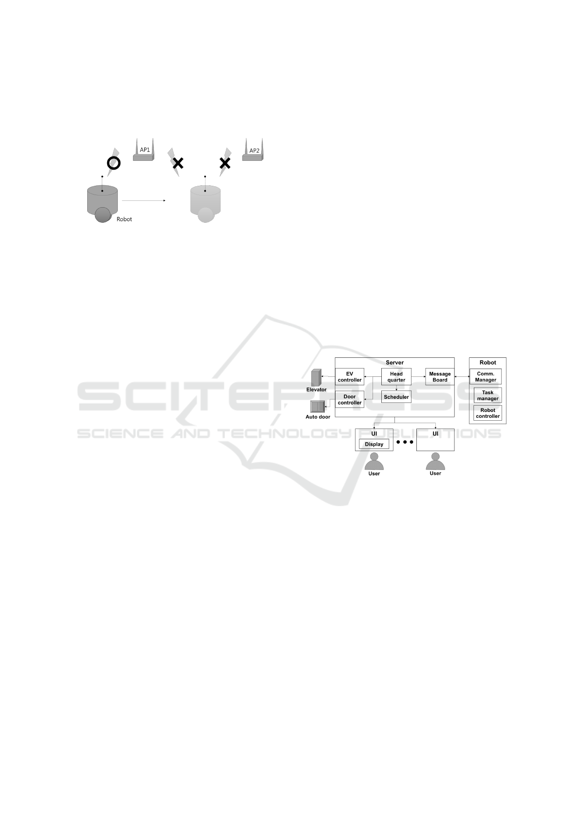
2.1 Network Environment
In this project, the multiple robots work in a spe-
cial environment that is wide and the network is fre-
quently disconnected. When a robot moves, the han-
dover of the access point (AP) occurs and the robot
loses connection from time to time. Also, the IP ad-
dress of the robot can be changed, in case of dynamic
assignment (DHCP) of AP. Thus, the online connec-
tion between a robot and the server cannot always be
guaranteed.
On the other hand, since the server uses a fixed
IP address, a robot can access to the server’s IP ad-
dress at any time when connected. Therefore, in this
delivery service architecture, the communication is
always initiated from the robot’s side. The connec-
tion is not always online, but, at least, we know that
some time the robot will be connected to the server
and receive messages. So, many of the decisions are
made by the robot itself, for example, planning the
path between delivery positions, avoiding obstacles,
controlling movements, and deciding the human in-
teraction behavior at each states. Network connection
is mandatory only when receiving the new task and re-
questing for usage of common resources. In general,
the robot reports its status to the server when possible.
To enable such communication method, the ’mes-
sage board’ concept is introduced in the server.
Whenever a robot is connected to the network, the
robot sends the heartbeat message to the server’s fixed
IP address and the heartbeat includes information of
the robot about its position and status. The returning
message of the heartbeat is any message that is posted
Multi-robot Control Architecture for Hospital Delivery Service in Unstable Network Environment
271
on the ’message board’. The server uses the message
board to assign a new task and to allow resource us-
age. The detail will be discussed in Sec. 3.1.3.
Figure 2: Network disconnection due to AP handover.
2.2 Delivery Service Scenario
The delivery contents in a hospital can be laboratory
samples, medicines, and medical supplies. Users of
the delivery service are nurses and staffs. They call
the delivery request from all around the hospital, for
example, nurses at wards on every floor, pathologists
at the laboratory, or staffs at the supply storage. They
will access on a web page on their computers or an
application of mobile devices to order a delivery ser-
vice. When a user enters a delivery task through the
web site, the delivery task is sent to the server and
stored in the server’s delivery task queue. When the
requested time has reached, the robot comes at the
user to load the item and brings it to other place.
Delivery Task. The delivery task is consisted of
time, contents and pick-up and drop-off positions.
The delivery request can be either periodic or on-
demand. The delivery waypoints can be one-to-
one, one-to-many, or many-to-one places. A user
can select these delivery type by the request.
The moment when the requested time has reached,
the server calls the scheduler module inside the server
to find an appropriate robot for the requested task.
The robot selection algorithm affects the total deliv-
ery performance and is discussed in (Jeon and Lee,
2016) and explained in Sec. 3.1.2. To sum up, the
scheduler reviews the current positions and task sta-
tus of all robots, and finds the robot that consumes
minimum cost for adding the new task.
When a robot is selected, the server assigns the
task to the robot, and the robot adds the new task in its
task queue. Assigning a delivery task to the robot are
performed based on the following sequence. When
the selection of a robot is finished by the scheduler,
the headquarter posts the task on the message board
of the selected robot ID such as ’Robot 3: Task 1,
Way points: A-B-C-D’. Whenever the 3rd robot sends
the heartbeat to the server, it receives the task as the
returning value of the heartbeat. Then, the robot gen-
erates the path between the waypoints of the task by
itself and starts delivery. The robot autonomously
moves to the pick-up point and waits for the user to
load items. When the user pushes button notifying
finished loading, the robot moves to the drop-off po-
sition and waits for unloading. If the unloading task is
finished, the robot moves to the next waypoint. This
task is repeated for the robot all day.
While delivering, there are common resources of
a building that robots use. Some of the resources can-
not be used by two robots at the same time. They
are an elevator, an automatic door and a narrow corri-
dor. These places are stored separately and managed
by the server to avoid conflict. When a robot arrives
at the places, the robot requests the usage of the re-
sources to the server. The server checks availability
and assigns the robot for the usage. The detail of the
resource usage procedure is explained in Sec. 4.3.
3 CONTROL ARCHITECTURE
Figure 3: The architecture of the multi-robot control system
for hospital delivery.
The proposing multi-robot control architecture for the
hospital delivery service in an unstable network en-
vironment is depicted in Figure 3. It is consisted of
a server, a UI, and a group of robots. Each agents
are connected through the network. The server man-
ages all data of robots, posts and receives messages
from robots, and controls resources such as the eleva-
tor and the automatic door. The UI is for the user to
order the delivery task from remote scattered places.
The data from UI is transmitted to the server to orga-
nize the task. A group of robots receives delivery task
from the server online and navigates the hospital au-
tonomously to perform the delivery task. A robot can
deliver more than one task at a time to increase the
delivery efficiency. Each agents consisting the system
is explained in detail as following sections.
ICINCO 2017 - 14th International Conference on Informatics in Control, Automation and Robotics
272

3.1 SERVER
3.1.1 Headquarter
The headquarter (HQ) manages all events while op-
erating robots. The updated information of robots
is managed here. It receives delivery requests from
UI and saves the delivery request in the task queue.
When, the server’s time meets the requested time, HQ
calls the scheduler and selects an appropriate robot
for the task. Then, the task is posted on the message
board. When there is a request from a robot to use a
common resource, such as an elevator or an automatic
door, HQ passes the request to the resource controller
to organize its usage.
3.1.2 Scheduler
The scheduler allocates the delivery task to an appro-
priate robot. If there is a standby robot, the sched-
uler assigns the task to the standby robot. If not, one
robot has to add the new task into its existing task
list. Which robot to add the new task is decided by
the scheduler. The inputs of the scheduler are all task
statuses and positions of robots, and the task schedule
from HQ’s task queue. The output of the scheduler
are the selected robot’s ID and its task sequence. The
task allocation algorithm selects the best robot for per-
forming the task.
The main concern of allocating a task to a robot is
minimizing the total travel distance and time. Thus,
the variables of the cost function becomes the dis-
tance. The best selected robot is the one which pro-
vides the minimum distance for performing the task
among all robots. The remaining battery and con-
tainer capacity act as constraints.
Difference in strategy of the task allocation algo-
rithm affects overall delivery performance. In this
project, we used the brute-force search method in the
algorithm to find the minimum cost of a robot. (Jeon
and Lee, 2016) That is, the scheduler generates all
possible combinations of pick-up and drop-off posi-
tions of the task list and calculates each combination’s
distance costs. By sorting the cost, the minimum cost
is selected, and the corresponding combination be-
comes the best task sequence of the robot. By com-
paring costs of all robots, the best robot and its task
sequence is selected.
3.1.3 Message Board
The unique feature of this multi-robot system that dis-
tinguishes with other robotic system is the message
board (MB). This is a part of the server that posts
all messages from HQ and robots. And, both HQ
and robots communicate by reading the posted mes-
sage. Unlike Blackboard architecture that has been
used for years, (Rudenko and Borisov, 2007) which
serves as a database for knowledge-based decision
making, MB exist only for posting messages. Once
the message is taken by the client, it is deleted from
MB. In many of the robotic system, the communica-
tion is conducted by the server sending the message
directly to the robot’s IP address, however, in our ap-
proach, the message is transmitted indirectly via MB.
In the real operating environment, the robot’s IP
address and its network signal is vague from the
server’s point of view. On the other hand, from the
robot’s point of view, the server is apparent and uses
the fixed IP address. Therefore, in this structure, the
server does not directly send a message to the robot
but only posting it on MB. Both the server and robots
communicate through this MB, regardless of the IP
address of a robot or unstable network environment.
When a robot sends the heartbeat to the server, it
receives the posted message as the returning value of
the heartbeat. The heartbeat message from the robot
includes the current position, status, task completion
status, and resource usage request. The message from
the server’s side includes the new task and permission
for the common resource usage. If a robot has to use
the elevator, the robot posts the request on the mes-
sage board. Then, the server checks MB frequently,
and passes this message between the resource con-
troller and robots. The messages are managed accord-
ing to the robot’s ID. This way online task allocation
in an unstable network environment become possible.
3.1.4 Resource Controller
Since this is a multi-robot system that covers multiple
floors, multiple requests from different robots can be
made to use the elevator. However, an elevator cannot
be used by two robots at the same time. Therefore,
the resource controller (RC) organizes these multiple
requests by either permitting the usage of the resource
or submitting the request on the queue and let the
robot to wait until the next permission. Several re-
quests can be made at the same time, however, RC
blocks other requests and permits only one usage at a
time. This way the robots can avoid deadlock situa-
tion when trying to use the resource simultaneously.
The common resources for the multi-robot system
includes an elevator, an automatic door, and a nar-
row corridor where two robots cannot move toward
each other at the same time. RC manages the entry of
robots to these resources. These common resources
are previously set during the installation of robots by
marking the resource area on the map and appointing
the waiting area in front of the resource place. The
Multi-robot Control Architecture for Hospital Delivery Service in Unstable Network Environment
273
waiting area is for the robot to wait before it is per-
mitted to enter.
3.2 Robot
3.2.1 Robot Controller
The robot controller manages general autonomous
navigation of the robot. The delivery task is a series
of waypoints. When a task is assigned to a robot, the
robot generates its path between waypoints and fol-
lows the path avoiding obstacles. It recognizes its po-
sition by sensory data. It performs the delivery task
sequence including the state change, such as move-
wait(load)-move-wait(unload). If a robot has to use
the elevator, it asks the server for the usage. Until
there is a permission from the server, the robot waits
on the waiting area. The control sequence of the re-
source usage is explained in Sec. 4.3.
3.2.2 Communication Manager
The communication manager (CM) of a robot exist
not only to send a message from a robot to the server,
but also to check whether the robot is connected to the
network. Since the working area of the robot cannot
guarantee online connectivity of the network, the CM
continuously checks the connectivity by sending the
heartbeat to the server periodically. The contents of
sending message of the heartbeat is generated by the
message handler. The returning message of the heart-
beat is anything that is posted on MB, which includes
the delivery task.
3.2.3 Message Handler
The message handler (MH) of a robot generates mes-
sages to send to the server and dispatches the message
received from CM. Any events that should be reported
to the server is managed in this module. The sending
message contains the robot’s position, status and task
completion status. When there is a need of a robot
to use the common resource, MH generates a request
message for the resource usage. The robot’s position
and status messages are refreshed to new data contin-
uously, whereas task status should obtain past history
since the last connection with the server.
MH dispatches the message received by the
server, and passes to the robot controller to behave
according to the message. If the received message is
a task, the robot performs the delivery. If the message
is permission for the resource usage, the negotiation
process for usage of resource is followed thereafter
as explained in Sec. 4.3. If there exist a returning
message of the heartbeat, which means the network
is connected and the message is sent, the MH erases
the past task completion status, and collects new task
history.
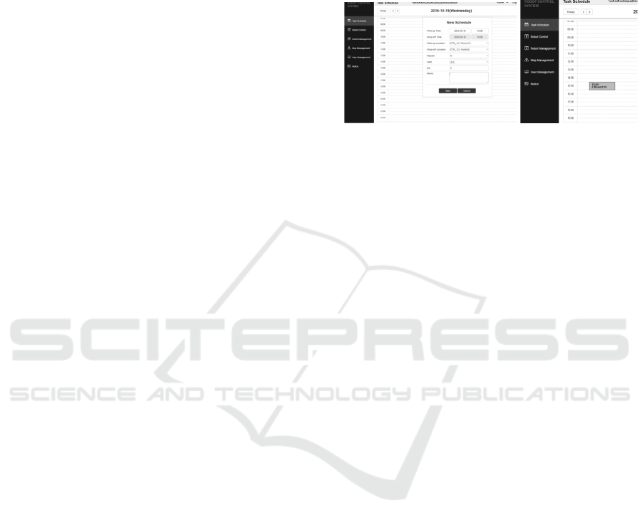
3.3 UI
(a) Task request on the web GUI (b) Schedule table
Figure 4: A screenshot of the task requesting web page.
The delivery service is requested from all around the
hospital, for example, nursing station of each floor,
supply storage, kitchen, laboratory, or anywhere the
user exists. Therefore, the user interface (UI) is sep-
arated from the server to satisfy the accessibility. UI
is an independent module that generates the task and
sends it to the server. It is preferred to be a web-page
style or a mobile application since these can be eas-
ily implemented in any system used by the hospital.
A user inputs a delivery request on UI, and the input
data is sent to the server and saved in the task sched-
ule. The example view of the web-based user inter-
face (UI) is in Figure 4. The user inputs time, user’s
and receiver’s name, contents, and pick-up and drop-
off positions.
4 COMMUNICATION
PROCEDURE
4.1 Task Assignment
When a user inputs a delivery request through UI, the
delivery task is sent to the task schedule of the server.
When the delivery time is reached, the server selects
a robot for performing the task through the scheduler,
and posts the delivery task on the message board with
the selected robot’s ID. This procedure is depicted in
Figure 5(a).
Since the delivery task is consisted of a pick-up
and a drop-off positions, the waypoints of the task
is the list of these visiting positions. If the delivery
task includes multi-floor task, the waypoints are seg-
mented including the waiting position of the elevator.
The server provides the list of waypoints for robot,
and robot plans path between waypoints.
ICINCO 2017 - 14th International Conference on Informatics in Control, Automation and Robotics
274
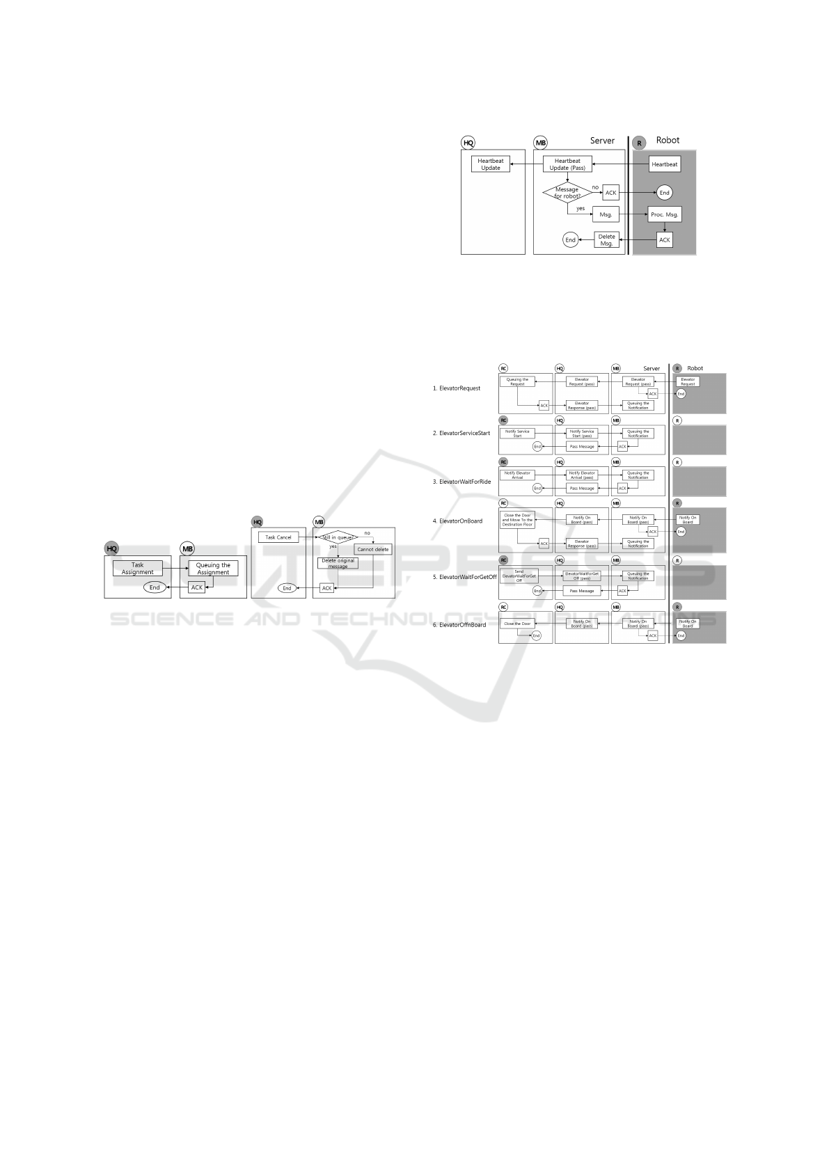
After posting the task message on the MB, the HQ
periodically checks whether the robot has received the
task. If the robot did receive the message, the robot
returns the ’received’ acknowlegement as the return
value of the heartbeat. Unless the acknowledgement
is received, the messages is regarded as ’not received’
by the robot. If the task message is not acquired by
the robot, the server can cancel the assignment with
the timeout option to prevent stuck delivery task.
When there is a need to cancel the assigned task
from the server’s side, the server checks whether the
robot has received the task. If the robot has not re-
ceived, the server can simply retreat the assigned task
by deleting the posted message. The procedure for
canceling the task from the server’s side is depicted in
Figure 5(b). However, if a robot has already received
the task, canceling the assigned task can be compli-
cated. There is a way to retreat the assigned task at the
robot’s side by letting the robot cancel and regenerate
its task sequence by itself and reporting the cancelled
result to the server. Since this can cause confusion,
enabling robot to cancel the task by itself should be
decided by the policy.
(a) Task assignment (b) Task cancel
Figure 5: Task messages from the headquarter to the mes-
sage board.
4.2 Heartbeat from Robot to Server
When operating the robot, all communication be-
tween the server and the robot is initiated from the
robot’s side. The heartbeat message is depicted in
Figure 6. MH maintains the current information of
a robot and binds the message for sending. CM pe-
riodically sends the heartbeat message to the server
containing the information generated from MH. Since
the server maintains the fixed IP address, the heart-
beat is directly sent to the server’s IP address. When
the network is connected, the information of the robot
is updated on MB. The new message on MB from the
server to the robot is received as the return value of the
heartbeat. The returning message can be a new task,
or a message related for the usage of the resource.
Figure 6: Heartbeat messages from the robot to the server.
4.3 Communication Procedure for
Using the Common Resource
Figure 7: The negotiation procedure for the usage of the
elevator.
When there is a need of a robot to use the common re-
source, the robot arrives at the waiting area and sends
the request message. The request message is posted
on MB. The HQ periodically checks MB, and when
there is a request for use the resource, HQ passes
the message to the corresponding RC. RC checks the
availability and if available, the RC sends permission.
HQ passes this permission to MB, and when the robot
receives the message from MB, the robot uses the re-
source.
Take an elevator for example, the negotiation pro-
cedure for the resource usage is depicted in Figure
7. Similar sequence is performed for other resources
such as the automatic door or the narrow corridor.
Multi-robot Control Architecture for Hospital Delivery Service in Unstable Network Environment
275
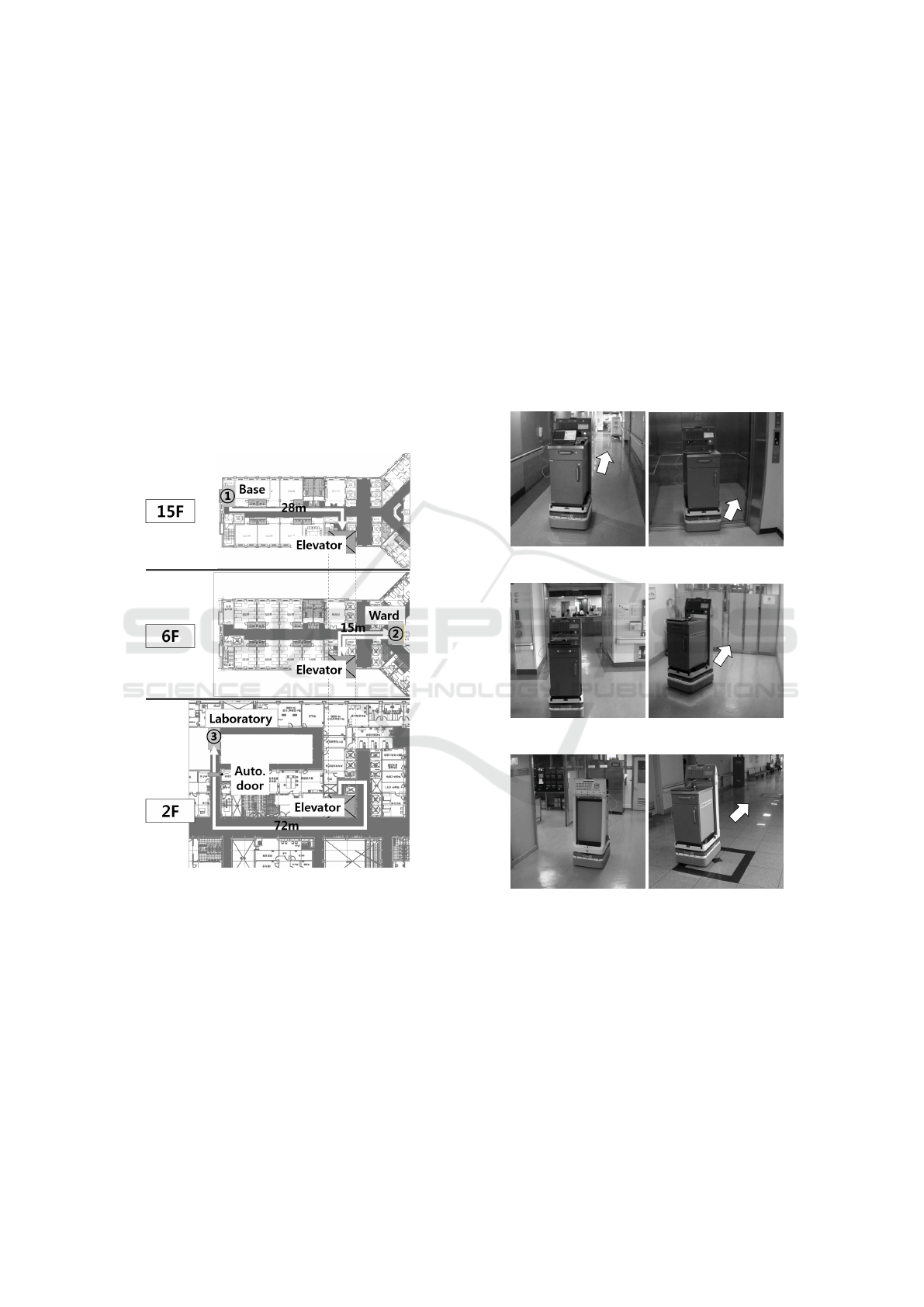
5 EXPERIMENTS
5.1 Testing Envoronment and Scenario
The proposing architecture is implemented in the
robotic system for delivery service and is tested in
the hospital. The robot is developed by ROS, and
the server is developed with web-based javascript on
Node.js. The robot and the server communicate via
RESTful. The testbed is in the Eulji hospital, Dae-
jeon, Korea. The server and UI is connected through
the wired network, and the robot is connected via
wireless network. The robotic system accessed the
hospital’s intra-network. The testing environment and
the pathway is depicted in Figure 8 and the scenario
is as follows.
Figure 8: The testing scenario for the hospital delivery ser-
vice. The nurse at 6th floor calls the robot to deliver the
sample to laboratory at 2nd floor. The base station is at 15th
floor.
1. The delivery request is made from the ward on 6th
floor.
2. The robot starts from the base station at 15th floor.
3. The robot calls and rides the elevator, and moves
to 6th floor.
4. It arrives at the ward and loads blood samples.
5. Then, it again calls and rides the elevator to the
2nd floor.
6. It moves to the laboratory on 2nd floor by passing
through the automatic door.
7. It arrives at the drop-off station of the laboratory
and unloads the item.
8. After finishing the task, it rides the elevator and
goes back to the docking station at 15th floor.
Due to the limited number of robots, we were able
to test only with one robot. However, the proposing
network architecture was able to be tested, and the
result shows that the network communication while
moving the wide area was conducted successfully.
Additional group of robots will be tested as the ex-
tension of this research.
(a) Moving to the eleva-
tor (15F)
(b) Riding the elelvator
(15F)
(c) Loading samples on
the ward (6F)
(d) Passing through the
automatic door (2F)
(e) Arriving at the lab-
oratory and unloading
(2F)
(f) Moving back to the
base (2F)
Figure 9: The experiment at Eulji hospital. Sequence from
(a) to (f).
5.2 Discussion About Floor Change
Detection
While testing, we found out that recognizing the floor
change of a robot when using the elevator is surpris-
ingly challenging problem for a robot. Unlike human,
ICINCO 2017 - 14th International Conference on Informatics in Control, Automation and Robotics
276

a robot cannot read the numbers in the elevator. Thus,
the robot cannot exit the elevator because the robot
is not sure that the elevator has arrived at the desired
floor. Several methods are tried to solve this problem.
One approach is the robot waits for the connection
to the network when the door is open and receives the
floor information from the server. However, connect-
ing to the network took as long as 1 minute, according
to our experiment.
Posting a marker in front of the elevator and de-
tecting with the vision sensor can be another ap-
proach. However, in this case, the marker should be
placed in the visible area where there is no obsta-
cle, and the marker should not be damaged. How-
ever, we couldn’t find an appropriate position to place
the marker in front of the elelvator since the wall is
far and the hospital didn’t want to place any artificial
mark on the building.
Third method we tried is using the wifi signal as
the fingerprint of the floor. (Lee and Kim, 2016) Since
this procedure of sensing the wifi signal is not for con-
nection but for matching the histogram of the obtained
signal, the result is converged in very short time, less
than 3 seconds after opening the door of the elelvator.
This way the robot can recognize the floor change as
well as save time for delivery.
6 CONCLUSIONS
This paper describes the problem about the multi-
robot control system within the unstable network en-
vironment. A fleet of robots are used in the hospital
for the delivery service. To enhance the performance
of using multiple robots, online task allocation is nec-
essary. However, since the online connectivity of the
network is not guaranteed, the server cannot directly
connect to the robot. Therefore, this paper proposes
a control architecture, used in such unstable network
environment. The proposing architecture applied the
message board on the server to communicate with the
robot. All messages from both the server’s and the
robot’s sides are posted on the message board. When
a robot is connected to the network, it sends the heart-
beat to the server containing robot’s information. The
robot receives the message from the server by the re-
turning value of the heartbeat. Always, the connec-
tion is initiated from the robot’s side. This way the
robot can communicate with the server not only to re-
ceive the new delivery task, but also to request the
usage of the common resources such as the elevator.
This architecture is tested in the real hospital environ-
ment, and the communication between the robot and
the server was performed successfully. This system
will be tested with more robots with the fleet opti-
mization algorithm in the future.
ACKNOWLEDGEMENTS
This material is based upon work supported by the
Ministry of Trade, Industry & Energy(MOTIE, Ko-
rea) under Industrial Technology Innovation Program.
No.10051155, ’The Development of Robot Based Lo-
gistics Systems Applicable to Hospital-wide Environ-
ment’.
REFERENCES
Alessandro Marino, Lynne E. Parker, G. A. F. C. (2013).
A decentralized architecture for multi-robot systems
based on the null-space-behavioral control with appli-
cation to multi-robot border patrolling. Journal of In-
telligent and Robotic Systems, 71(3–4):423–444.
Ali Gurcan Ozkil, e. a. (2009). Service robots for hospitals:
A case study of transportation tasks in a hospital. In
International Conference on Automation and Logis-
tics (ICAL), pages 289–294. IEEE.
Bloss, R. (2011). Mobile hospital robots cure numerous lo-
gistic needs. Industrial Robot: An International Jour-
nal, 38(6):567–571.
Harrisson Fischer, Philippe Vulliez, J.-P. G. S. Z. (2016).
An industrial standard based control architecture for
multi-robot real time coordination. In International
Conference on Industrial Informatics (INDIN), pages
207–212. IEEE.
Jeon, S. and Lee, J. (2016). Multi-robot multi-task alloca-
tion for hospital logistics. In International Conference
on Advanced Communication Technology (ICACT),
pages 339–341. IEEE.
Lee, Y.-C. and Kim, J. (2016). Multi-floor localization
method for mobile robots using elevator. In Inter-
national Conference on Control, Automation and Sys-
tems (ICCAS), pages 869–872. IEEE.
Niechwiadowicz, K. and Khan, Z. (2008). Robot based lo-
gistics system for hospitals-survey. In IDT Workshop
on interesting results in computer science and engi-
neering.
Ren, W. and Sorensen, N. (2008). Distributed coordi-
nation architecture for multi-robot formation control.
Robotics and Autonomous Systems, 56(4):324–333.
Rudenko, D. and Borisov, A. (2007). An overview of black-
board architecture application for real tasks. Scientific
Proceedings Of Riga Technical University, 5:50–57.
Yasuhisa Hirata, Y. S. and Kosuge, K. (2015). Control
architecture of delivery robot for supporting nursing
staff. In International Symposium on System Integra-
tion (SII), pages 345–351. IEEE/SICE.
Multi-robot Control Architecture for Hospital Delivery Service in Unstable Network Environment
277
