Applying Peg-in-Hole Actions with a Service Robot
Stefan-Daniel Suvei
1
, Leon Bodenhagen
1
, Thomas Nicky Thulesen
1
, Milad Jami
2
and Norbert Kr
¨
uger
1
1
University of Southern Denmark, 5230 Odense M, Denmark
2
Novo Nordisk A/S, Novo Alle, 2880 Bagsvaerd, Denmark
Keywords:
Service Robot, Peg-in-Hole, Simulation.
Abstract:
A general requirement for any service robot is to be flexible and capable of processing uncertainties, thus
making it adaptable for multiple tasks. As a result, learning the appropriate action parameters for a specific
action is a crucial task. The method presented in this paper is an incremental statistical learning method
that takes into consideration the uncertainties and the contact forces to find the optimal parameter sets. The
method is inspired by solutions available in industrial robotics and it uses a dynamic simulator and Kernel
Density Estimation in order to find the parameter sets that lead to a successful Peg-in-Hole action. The
solution obtained in the simulation is successfully tested on a real service robot.
1 INTRODUCTION
In industry, robotic solutions are well established.
One reason that facilitates the application of these
solutions is that the environment can be controlled,
such that uncertainties and thereby error sources are
minimized. Current approaches focus on enabling
robots to solve tasks despite of uncertainties. So-
lutions for handling uncertainties in e.g. assembly
processes include online pose estimation of relevant
items (Schwarz et al., 2015), use compliant manipula-
tors (Kashiri et al., 2014) or utilize re-planning (Main-
price et al., 2015).
Within the domain of service robotics, the prob-
lem of correctly handling uncertainties is crucial,
in particular when considering the fact that service
robots have to work in unstructured and dynamic en-
vironments where they need to assist or work along-
side humans. The challenge is to apply some of the
well-tested industrial solutions in the service robotics
field. This is due to the fact that safety, the ease of use
and the flexibility are important aspects that need to
be considered when talking about a service robot.
A good example of a process that can be trans-
ferred into service robotics from the industry and in
which uncertainties can create big challenges is the
classical tight fitting Peg-in-Hole (PiH) process (Di-
etrich et al., 2010),(Lin et al., 2014). Viewed mostly
as an industrial, assembly type of task, many tasks
in the field of service robotics such as collecting bot-
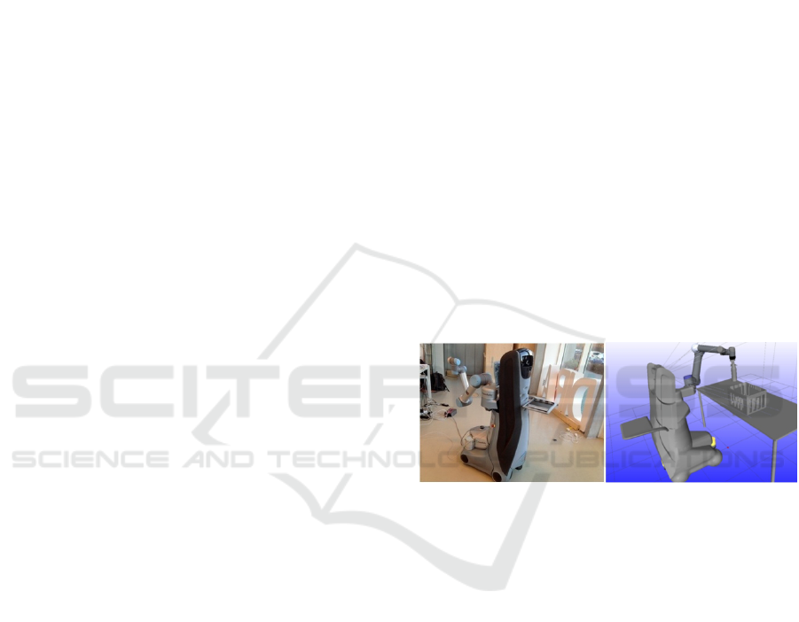
Figure 1: Care-O-Bot architecture. Left: Real platform.
Right: Simulated platform.
tles, disposing of trash or inserting cutlery into the
dishwasher compartiments can be consider to be PiH
actions.
Manually tuning the parameters that normally de-
fine the PiH action is challenging, since there is no
guarantee that the selected solution will be successful
for each trial. Sensor-controlled actions can be used
to handle this type of situations, however, this gener-
ally leads to an increase in the overall process-time
and cost.
Another approach is to use action parameter opti-
mization techniques to reduce the number of samples
in the search space, like in (Sørensen et al., 2016),
where Kernel Density Estimation is used during the
learning phase to eliminate the sub-optimal areas of
the search space. This is done by considering the re-
sult of the experiments in the surrounding neighbor-
hood.
Our proposed method makes use of a dynamic
simulator and Kernel Density Estimation to do a post-
224
Suvei, S-D., Bodenhagen, L., Thulesen, T., Jami, M. and Krüger, N.
Applying Peg-in-Hole Actions with a Service Robot.
DOI: 10.5220/0006401702240231
In Proceedings of the 7th International Conference on Simulation and Modeling Methodologies, Technologies and Applications (SIMULTECH 2017), pages 224-231
ISBN: 978-989-758-265-3
Copyright © 2017 by SCITEPRESS – Science and Technology Publications, Lda. All rights reserved

learning search through the parameter space and find
those sets that lead to a successful Peg-in-Hole ac-
tion. In order to eliminate unpromising parameter
sets, process uncertainties and the appearance of con-
tact forces are taken into consideration. The result is
tested and verified on both a simulated and a real plat-
form.
2 RELATED WORK
With the rise of interest for service robotics, classical
robotic topics such as safe planning, visual servoing
and manipulation have recently regained focus, with
the goal of adapting some of the well-known indus-
trial methods to the more challenging home environ-
ment. Action-parameter learning, in particular, has
been of great concern, specifically because it is ap-
plicable to a large array of tasks, thus increasing the
flexibility of the system. The learning process can be
done using the execution feedback data received from
the sensors and adapting the action process accord-
ing to the found environment constraints (Gams et al.,
2014), (Berio et al., 2016), by human demonstration
(Gams and Petri
ˇ
c, 2016) or by using dynamic simu-
lation, thus facilitating an extended exploration of the
parameter space (Jørgensen and Petersen, 2008), (De-
try et al., 2011), (Sørensen et al., 2016).
As opposed to industrial robots, service robots
have to be flexible in order to function in unstructured
and dynamic environments. As such, a rigid calibra-
tion of the tested setup is not a viable solution. For
systems that are required to manipulate the environ-
ment and are equipped with a camera, a way of over-
coming this issue is through position based visual ser-
voing (PBVS) (Cherubini et al., 2008). This method
uses the difference between the pose of the desired
target object and that of the manipulator to determine
the control error. For the target object, the pose es-
timation can be determined by using a 3D model of
the object and the homography, like in (Kyrki et al.,
2004). (Gratal et al., 2011) proposes an alternative
solution, by using a real-time model-based tracking
method to estimate the pose of the gripper.
Compared to other approaches, we address the
PiH task of inserting bottles into a crate using a ser-
vice robot, for which no special calibration, specific
environment manipulation (i.e. light adjustment, po-
sition control, etc.) or additional sensors (such as
force-torque sensors or compliant grippers) are used.
PBVS and dynamic simulation are utilized in order to
achieve the task with minimum contact force. The pa-
rameter set that describes the tested PiH action, along-
side the actual action path are determined in simula-
(a) Original RGB data (b) Modified RGB data
Figure 2: Visualization of the Aruco traker output - the two
markers are detected and the transformations between them
and the camera are computed.
tion. We demonstrate that the solution found in sim-
ulation can be directly used on a real platform, where
the PiH action is not only successful, but also gener-
ates low contact forces.
3 EXPERIMENTAL SETUP AND
METHODOLOGY
The Care-O-Bot (Graf et al., 2009) is a robotics plat-
form that was developed to be a mobile robot assis-
tant that actively supports humans in domestic envi-
ronments. A big advantage of the Care-O-Bot plat-
form (see Figure 1) is that it is equipped with multi-
ple sensors and has a modular hardware setup, which
makes it fit for a large array of tasks, such as: pick-
and-place, object detection, human tracking, etc. The
main components of the Care-O-Bot are: the omnidi-
rectional mobile base, an actuated torso with 3 DoF,
the UR5 robotic arm, the UR connector (to which the
arm is attached), the tray, the head (which contains a
Carmine 3D Sensor and a high resolution stereo cam-
era) and three laser scanners. Using this platform, we
investigate the possibility of solving a PiH task that
consists of inserting bottles into a crate and learn the
best parameter sets that define this action.
3.1 Tracking and Visual Servoing
The PBVS method determines the error between the
pose estimation of the end effector and that of the de-
sired object (in this case, the bottle crate) and uses it
as a control error, in order to move the arm towards
the desired position. As follows, the control loop is
an endpoint closed loop, where both the end effector
and the crate are in the field of view.
To ease the process of pose estimation and track-
ing, two AR (Augumented Reality) markers, de-
noted M1 and M2 in the following, are attached to
the gripper and the bottle crate. With the help of
the ”aruco ros” ROS tracker (Garrido-Jurado et al.,
Applying Peg-in-Hole Actions with a Service Robot
225
2014), the markers are detected and the transforma-
tion between them is determined. The obvious down-
side of this approach is that the markers must con-
stantly be detectable by the camera, which makes it
sensitive to the illumination level in the environment,
specifically since the robot was placed in a laboratory
with a lot of natural light. To overcome this issue,
we apply the Contrast Limited Adaptive Histogram
Equalization algorithm (Zuiderveld, 1994) on the in-
put RGB image data of ”aruco ros” tracker, thus im-
proving the overall contrast of the image, as can be
seen in Figure 2, and aiding the corner detection.
The two transformations are used in a classic lin-
ear interpolation algorithm that generates the incre-
mental displacements that will move the robotic arm
with the end effector towards the crate and decrease
the pose estimation error between the two AR mark-
ers.
The algorithm is repeated until the Euclidean dis-
tance between the two markers is smaller than a pre-
defined threshold which will ensure that the gripper is
placed above the crate. To avoid overshooting this po-
sition, the incremental displacements decrease as the
Euclidean distance between the markers decreases.
Once the desired position is reached, the algorithm
updates the position of the crate based on a final read-
ing of the M2 marker and then starts the Peg-in-Hole
action sequence.
Figure 3: The PiH action parameters.
3.2 Action Parametrization
The Peg-in-Hole action in our context is defined by
two parameters (Figure 3) and is performed in four
steps (Figure 4). The parameters span the search
space and are defined as follows:
x: The perpendicular distance between the hole and
the middle of the bottle bottom.
φ: The angle of the bottle in the initial position
relative to the hole vertical axis.
If we assume an ideal PiH action (i.e. no uncer-
tainties), the four steps that compose the action as a
whole are described as follows:
Initial Position: In the first step the robot moves the
(a) (b) (c) (d)
Figure 4: The PiH action movements: (a) First linear mo-
tion. (b) Circular motion. (c) Second linear motion.
(d) Final position.
bottle from the position where it was left by the vi-
sual servoing algorithm towards the hole. At the end
of this motion, the bottle is at a perpendicular distance
of 5cm from the hole and tilted with an angle φ.
First Linear Motion: In the second step, the bottle
is moved linearly towards the hole (Figure 4(a)). The
movement stops when the end of the bottle is at a per-
pendicular distance X above from the hole. At this
point, the bottle is touching the edge of the hole.
Circular Motion: After the first linear movement and
the contact with the hole’s edge, the bottle is rotated
until φ = 0, as depicted in Figure 4(b).
Second linear Motion: In the final step, the bottle is
moved linearly down the hole and the bottle’s axis is
kept aligned with the hole (Figure 4(c)). In our pro-
posed solution, when the bottom of the bottle is inside
the hole after the second linear motion, the robot just
drops the bottle into the hole.
The PiH action is evaluated after the second linear
motion. For a successful action, the bottle has to be
partially inside the specified crate hole, such that a
simple release of the gripper would drop it in the hole
(see Figure 4(d)). This is confirmed by checking the
pose of the bottle with respect to the hole. In the case
in which the bottle gets stuck by hitting the edge of
the hole, the action is labeled as a failure.
Using the described steps, the relative path be-
tween the bottle and the hole is computed for each
parameter set. This path is then executed in both the
simulated environment and on the real world setup.
The evaluation and labeling of the action (i.e. suc-
cess of failure) is done automatically in simulation
and manually for the real world platform.
3.3 Action Simulation
The action simulation is performed using different
values for the action parameters. The ranges of the
parameters are set beforehand and define the search
space. As such, the action is simulated within the pa-
rameter ranges of x ∈ [−3; 3]cm and φ ∈ [−45; 45]
◦
,
SIMULTECH 2017 - 7th International Conference on Simulation and Modeling Methodologies, Technologies and Applications
226
(a) Success probability map (b) Force profile map
(c) Success probability map KDE (d) Force profile map KDE
Figure 5: The success probability map and the force profile map before and after KDE.
with step sizes of 5 mm and 2
◦
respectively.
To allow the learning sequence to deal with uncer-
tainties, positional and rotational noise is added to the
bottle frame and the hole frame in the action simula-
tion. This is done by randomly choosing a direction
from the XYZ-axes and multiplying it with a random
value from a normal distribution to the chosen direc-
tion. For the crate, the normal distribution has a mean
value of zero and a standard deviation of 3.5mm for
the position and 3
◦
for the rotation. For the bottle, the
standard deviation is 1mm and 0.5
◦
for the positional
and the rotational noise respectively. The ranges of
the uncertainties are based on the geometric models of
the bottle and crate used in the simulator and on pre-
liminary simulation tests. Due to the fit of the bottle
and the hole, any positional error larger than 2.5 mm
on one of the XY-axes or a rotational error larger than
0.8
◦
on one of the PY-Euler angles will result in the
bottle getting stuck on the edge of the crate or apply-
ing forces on the crate, as observed in initial simula-
tion tests.
3.4 Action Learning
To learn the parameter values that will lead to a suc-
cessful task, the action is simulated 5 times for each
pair of parameters, where the perturbation for each
pair of samples is randomly selected as explained in
the previous paragraph. This leads to a total number
of 2925 individual tests of the PiH action. The results
are visualized using a success probability map as in
Figure 5(a).
To further narrow down the solution parameter
space, we also investigate the force profile of the ac-
tions. For each parameter set, the average of the high-
est contact forces that characterized each repetition is
computed. A threshold is used to limit the maximum
allowed force to 150 N. The forces distribution can be
seen in Figure 5(b). We note that the measured con-
tact force is between the bottle and the hole for which
the insertion is tested. For this reason, in the upper-
right corner of the map, where the bottle is colliding
with the crate (but not with the actual hole edges) it
seems that there are little to no contact forces.
The next step is to multiply the Kernel Density
Estimations of the success probability map and of the
forces distribution, in order to choose a set of parame-
ters for which the action would be successful, while at
the same time the contact force between the bottle and
crate would be minimal. The result (seen in Figure 7)
is further discussed in section 4.1.
4 RESULTS
In this section, we show how by applying KDE on
the results of the Action Learning sequence, we can
Applying Peg-in-Hole Actions with a Service Robot
227
(a) Real world experiment
(b) Real world experiment with added noise
Figure 6: The KDE representation of the success and force profile of the 10 tested parameter sets. The parameter sets are
marked with the red dots. The best set is marked with the black dot.
Figure 7: The multiplied KDE representation of the success
and force profile.
reduce the parameter space and find good parameter
sets that would yield a successful PiH action. We fur-
ther test a subset of the parameters on the real plat-
form and compare the result with the simulated ones.
4.1 Optimal Actions in Simulation
As mentioned in section 3.4, Kernel Density Esti-
mation is used for both the success probability (Fig-
ure 5(a)) and the force profile map (Figure 5(b)) to
get a good overview of the structure of the data and a
good approximation of the best parameter sets.
The Matlab implementation of the KDE via dif-
fusion method (Botev et al., 2010) is used, in which
we use a multivariate Gaussian kernel and we de-
fine each independent data sample as a vector of type
s = [x; φ; d], where x and φ are the two PiH action
parameters and d is either the success probability or
the force value for that specific parameter set. The
value of d is the one that decides the smoothing con-
tribution of each specific [x, φ] parameter set. In this
specific Matlab implementation, the kernel density is
estimated based on the smoothing properties of lin-
ear diffusion processes. If we consider (s
1
, s
2
, . . . , s
n
)
independent samples from an unknown continuous
probability function f , then the kernel density esti-
mator is defined as:
ˆ
f (s) =
1
nh
n
∑
i=1
e
−
(s−s
i
)
2
2h
2
√
2π
(1)
where h is the bandwidth and s is the point for which
the density is estimated.
As shown in (Botev et al., 2010), the construction
of a kernel density estimator can be (from a mathe-
matical perspective) compared to the process of com-
puting the amount of heat generated when heat ker-
nels are placed at each s
i
sample point. Knowing
that a heat kernel is the fundamental solution of the
SIMULTECH 2017 - 7th International Conference on Simulation and Modeling Methodologies, Technologies and Applications
228

Fourier heat equation,
ˆ
f (s) can be computed. The ad-
vantage of this approach is that it also introduces a
plug-in bandwidth selection method which uses the
asymptotic properties of the resulting
ˆ
f (s) estima-
tor to compute the asymptotically optimal plug-in
bandwidth h, without requiring any numerical opti-
mization, thus speeding up the process of finding the
promising parameter sets.
Because we are interested in finding the parameter
sets that yield both a success and a low contact force
between the bottle and the crate, a summation of the
two KDE’s (see Figure 7) is used for a better repre-
sentation of the data and the search space. Finding
the best parameter set means finding the maximum
of the density surface. This can be done by apply-
ing optimization algorithms, such as gradient ascent.
However, due to the nature of the data and because
the density is represented by a matrix where its size
is defined by the x and φ parameters and the individ-
ual density values depend on d, the best parameter set
can be found by computing the maximum value of the
matrix. The best parameter set is found to be [3.5mm,
5
◦
]. Visualizing the KDE data representation, we can
observe that the density curve also has a second peak,
around [−10 mm, −30
◦
]. These two peaks correspond
to the main successful areas of the search space, rep-
resented in Figure 5(a) and Figure 5(c) and to the
lower force areas, as shown in Figure 5(b) and Fig-
ure 5(d). The success of the PiH action drops in-
between these two peaks due to the fact that the bottle
gets stuck on the edge of the hole and also applies
force on the crate.
4.2 Verification on Real System
Compared to the real world case, the simulator is
more conservative because the slippage between the
bottle and the plastic gripper or the compliance of the
bottle, which can endure a big amount of deformation
before actually breaking, are not considered in sim-
ulation. Both of these phenomenons can potentially
lead to accidental successful trials, thus leading to a
wrong prediction of the outcome.
Based on the results obtained in the previous sub-
section, a set of real world experiments were per-
formed. The experiment starts with the visual servo-
ing part, as described in 3.1, where the robot arm is
moving the bottle towards the crate. Once the bottle
is at the desired position, the PiH action is performed,
using specified parameters as input (see Figure 8).
Aside from executing the selected ”best” parameter
set, we also investigate 9 other sets, chosen manually
from both promising and non-promising areas found
by the simulation phase in an attempt to show that the
real world results align with the ones found by simula-
tion. Each of the sets is tested 10 times and evaluated
manually. This means that the d value for each of the
individual samples s
i
∈(s
1
, s
2
, . . . , s
100
) has one of the
following values:
d =
0, if bottle fell from the gripper
1, if failure, with contact force
2, if success, with big contact force
3, if success, with medium contact force
4, if success, with small contact force
5, if success, with no contact force
Following the method described in the previous
subsection, we also apply KDE on the outcome of the
real world experiments (see Figure 6(a)). Analyzing
the KDE result, we can observe that the pattern of the
density curve is similar to the one suggested by the
simulation results in Figure 7. Additionally, the best
parameter set - found to be [3.5 mm, 5
◦
] by the simu-
lator - had a success rate of 100% on the real platform.
The parameter set [−10 mm, −30
◦
] corresponding to
the second peak had a success rate of 70%, thus con-
firming the validity of the data. The [−2.5 mm, −15
◦
]
and [5mm, 25
◦
] parameter sets also gave good results
due to the compliance and curved shape of the bottle,
which makes the insertion possible even if the edge of
the hole is touched.
As mentioned, the robot is not equipped with
a force-torque sensor. On order to verify that the
assumption about the forces is correct, a third AR
marker, was placed on the side of the crate. The
idea is that, when force is applied, the crate is moved
and thus the movement of the marker can be detected.
Moreover, we verify if the scale of the movement is
proportional to the strength of the contact force.
The translational movement of the AR marker is
investigated by tracking how the length of the position
vector (defined for the marker frame) changes over
the course of the PiH action. Similarly, the rotation
is checked by tracking the changes in quaternion an-
gles during the action performance (see Figure 6(a)).
The spikes in the translation and rotation appear at the
moment any kind of contact force is applied. For the
[3.5mm, 5
◦
] parameter set, we can see that there is
only sub-millimeter and sub-degree movement, thus
suggesting that no major force is applied to the crate.
The registered movement is due to the fact that the
marker can be correctly tracked only within millime-
ter precision, so anything bellow that will be affected
by noise. The spikes that appear around the 460 mark
are generated by the bottle falling into the crate hole
when it is released from the gripper. On the other
hand, for the [10mm, −30
◦
] parameter set we can ob-
serve that when the bottle hits the edge of the crate,
Applying Peg-in-Hole Actions with a Service Robot
229

the tracker registers a movement of more than 3 mm in
translation and 2.5
◦
degrees in rotation. This suggests
that a bigger contact force is applied, which aligns
with the force estimation results in Figure 5(d) and
Figure 7.
4.3 Addition of Positional Noise
To further test the validity of the simulation results,
we opt to make a series of real world experiments
where we add extra positional uncertainty by not al-
lowing the system to update the position of the crate
before performing the PiH sequence. This means that
the robot blindly performs the PiH action, assuming
that the crate is placed in the correct position.
We investigate the same 10 parameter sets that
were tested in 4.2, again with 10 trials for each (a to-
tal of 100 experiments). The results are shown in Fig-
ure 6(b). It can be observed that, while some peeks
decrease compared to the case shown in Figure 6(a)
due to the appearance of higher forces, the data is
following a similar pattern to the one shown in the
previous subsection and as estimated by the simula-
tor. The best parameter set had again a success rate
of 100%. However, the success rate of the [−10mm,
−30
◦
] peak dropped to only 10%, thus proving that
not being able to update the position of the crate has
a huge impact on the success probability, even if the
positional difference is less than a few millimeters.
The movement of the side marker is also tracked
and the results are shown in Figure 6(b). For the good
parameter set [−2.5 mm, −15
◦
], little movement is
registered by the tracker, thus suggesting that no ma-
jor contact forces are applied on the crate during the
PiH action execution. The peak at the 520 mark is due
to the bottle dropping into the crate. For the [−5 mm,
−35
◦
] parameter set, a large movement of 1cm in
translation is registered, which suggests that the crate
was pushed hard with the bottle, once again confirm-
ing the force estimation results in Figure 5(d) and Fig-
ure 7. These results show that the robot will fail even
when using some of the good parameter sets, if the
positional error is larger than a few centimeters and if
the system is not allowed to update and compensate
for it, thus underlining the importance of considering
the uncertainties when performing such a task.
5 FUTURE WORK
The presented method has shown that industrial so-
lutions can be used and applied successfully with a
service robot, in a home-like environment. Future re-
search will have to consider other industrial tasks that
could be adapted and used in similar service robotics
scenarios. In addition, because some of these tasks
are collaborative in nature, an investigation of the so-
cial implications of the human-robot interaction could
be carried out.
6 CONCLUSIONS
In this paper an industrial-robotics inspired approach
to solve the Peg-in-Hole task of inserting bottles into
a crate is proposed. The work is performed using the
Care-O-Bot service robot, without making use of ad-
ditional, specialized sensors, calibration or compliant
grippers. If we consider the parameterization of the
PiH action, as described in 3.2, than the goal of the
proposed method is to find the best parameter sets -
i.e. parameters for which the PiH action yields both
a successful insertion of the bottle and a low or non-
existing contact force. The method starts by explor-
ing the parameter search space. This is done by it-
eratively simulating the PiH action together with us-
ing a learning algorithm that takes into consideration
the process uncertainties and the contact forces. Us-
ing Kernel Density Estimation, the parameter space is
then reduced to a subset of promising parameters.
Making use of this knowledge, real world experi-
ments are performed with the Care-O-Bot platform.
10 different parameter sets are selected from both
promising and non-promising areas of the parame-
ter space, as proposed by the learning algorithm, for
which the PiH action is repeated for 10 times. We
perform 200 experiments in two series - first by just
running the action path and secondly by adding an
additional position error, by not allowing the robot
to update the position of the crate before perform-
ing the PiH action. Both experiment series showed
that the real world results align with the ones found
by the learning algorithm. More specifically, the best
parameter set proposed by the learning component
proved to have a success rate of 100%. This proves
that adapting and applying solutions developed for the
industrial robotics field is a viable option for service
robotics, as long as the task uncertainties arising from
the unstructured environment in which a service robot
normally has to operate are taken into account.
ACKNOWLEDGEMENTS
This work was supported by Patient@home, funded
by the Danish Innovation Fond, and Health-CAT,
funded by European Regional Development Fund.
SIMULTECH 2017 - 7th International Conference on Simulation and Modeling Methodologies, Technologies and Applications
230

Figure 8: The full action sequence: visual servoing (1-4) and Peg-in-Hole (5-6).
REFERENCES
Berio, D., Calinon, S., and Leymarie, F. F. (2016). Learn-
ing dynamic graffiti strokes with a compliant robot.
In IEEE/RSJ Int. Conf. on Intelligent Robots and Sys-
tems, pages 3981–3986.
Botev, Z. I., Grotowski, J. F., Kroese, D. P., et al. (2010).
Kernel density estimation via diffusion. The Annals of
Statistics, 38(5):2916–2957.
Cherubini, A., Chaumette, F., and Oriolo, G. (2008). A
position-based visual servoing scheme for following
paths with nonholonomic mobile robots. In IEEE/RSJ
Int. Conf. on Intelligent Robots and Systems, pages
1648–1654.
Detry, R., Kraft, D., Kroemer, O., Bodenhagen, L., Peters,
J., Kr
¨
uger, N., and Piater, J. (2011). Learning grasp
affordance densities. Paladyn Journal of Behavioral
Robotics, 2(1).
Dietrich, F., Buchholz, D., Wobbe, F., Sowinski, F., Raatz,
A., Schumacher, W., and Wahl, F. M. (2010). On con-
tact models for assembly tasks: Experimental investi-
gation beyond the peg-in-hole problem on the exam-
ple of force-torque maps. In IEEE/RSJ Int. Conf. on
Intelligent Robots and Systems, pages 2313–2318.
Gams, A. and Petri
ˇ
c, T. (2016). On-line modifications of
robotic trajectories: Learning, coaching and force vs.
position feedback. In Int. Conf. on Robotics in Alpe-
Adria Danube Region, pages 20–28. Springer.
Gams, A., Petric, T., Nemec, B., and Ude, A. (2014). Learn-
ing and adaptation of periodic motion primitives based
on force feedback and human coaching interaction.
In IEEE-RAS Int. Conf. on Humanoid Robots, pages
166–171.
Garrido-Jurado, S., noz Salinas, R. M., Madrid-Cuevas, F.,
and Mar
´
ın-Jim
´
enez, M. (2014). Automatic generation
and detection of highly reliable fiducial markers under
occlusion. Pattern Recognition, 47(6):2280 – 2292.
Graf, B., Reiser, U., H
¨
agele, M., Mauz, K., and Klein, P.
(2009). Robotic home assistant care-o-bot 3 - product
vision and innovation platform. In IEEE Workshop on
Advanced Robotics and its Social Impacts.
Gratal, X., Romero, J., and Kragic, D. (2011). Virtual visual
servoing for real-time robot pose estimation. IFAC
Proceedings Volumes, 44(1):9017–9022.
Jørgensen, J. A. and Petersen, H. G. (2008). Usage of sim-
ulations to plan stable grasping of unknown objects
with a 3-fingered Schunk hand. In IEEE Int. Conf.
on Intelligent Robots and Systems, Workshop - Robot
simulators: available software, scientific applications
and future trends.
Kashiri, N., Laffranchi, M., Tsagarakis, N. G., Margan,
A., and Caldwell, D. G. (2014). Physical interac-
tion detection and control of compliant manipulators
equipped with friction clutches. In IEEE Int. Conf. on
Robotics and Automation, pages 1066–1071.
Kyrki, V., Kragic, D., and Christensen, H. I. (2004).
New shortest-path approaches to visual servoing. In
IEEE/RSJ Int. Conf. on Intelligent Robots and Sys-
tems, pages 349–354.
Lin, L. L., Yang, Y., Song, Y. T., Nemec, B., Ude, A., Rytz,
J. A., Buch, A. G., Kr
¨
uger, N., and Savarimuthu, T. R.
(2014). Peg-in-hole assembly under uncertain pose
estimation. In Proc. of the 11th World Congress on In-
telligent Control and Automation, pages 2842–2847.
Mainprice, J., Hayne, R., and Berenson, D. (2015). Predict-
ing human reaching motion in collaborative tasks us-
ing inverse optimal control and iterative re-planning.
In IEEE Int. Conf. on Robotics and Automation, pages
885–892.
Schwarz, M., Schulz, H., and Behnke, S. (2015). RGB-
D object recognition and pose estimation based on
pre-trained convolutional neural network features. In
IEEE Int. Conf. on Robotics and Automation, pages
1329–1335.
Sørensen, L. C., Buch, J. P., Petersen, H. G., and Kraft, D.
(2016). Online action learning using kernel density
estimation for quick discovery of good parameters for
peg-in-hole insertion. In 13th Int. Conf. on Informatics
in Control, Automation and Robotics.
Zuiderveld, K. (1994). Contrast limited adaptive histogram
equalization. In Graphics gems IV, pages 474–485.
Academic Press Professional, Inc.
Applying Peg-in-Hole Actions with a Service Robot
231
