Sensor Fusion of a 2D Laser Scanner and a Thermal Camera
Johanna Gleichauf, Christian Pfitzner and Stefan May
Technische Hochschule N
¨
urnberg Georg Simon Ohm, Kesslerplatz 12, Nuremberg, Germany
Keywords:
Sensor Fusion, Calibration, 2D Laser Scanner, Thermal Camera.
Abstract:
In order to increase the robustness of localisation and victim detection in low visibility situations it is necessary
to fuse several sensors. The most common sensor used in robotics is the 2D laser scanner which delivers
distance measurements. In combination with a camera the gained information can be supported by visual
information about the environment. Thermal cameras are ideal for finding objects with a certain temperature,
but they do not deliver distance information. The difficulty in fusing these two sensors is, that a correspondence
between each distance measurement and its corresponding pixel within the thermal image needs to be found.
As the laser scanner only displays one plane, this is not an intuitive task. A special triangular calibration
target, covering all six degrees of freedom and being visible for both sensors, was developed. In the end
the transformation between each laser scan point and its corresponding thermal image pixel is given. This
allows for assigning every laser measurement within the field of view a corresponding thermal pixel. The final
application will enable detection of human beings and display the distance required to reach them.
1 INTRODUCTION
For allowing robust localisation and victim detection
sensor fusion of several sensors with different proper-
ties is needed. As the aim is to find possible victims in
for example environments with great smoke emission,
sensors applicable for this situation are required. The
proposed sensor fusion system is made up of a ther-
mal camera, a Short Wave Infrared (SWIR) camera, a
laser scanner and a radar sensor. Laser scanners have
limits in poor visibility situations. That is why radar
sensors are a robust alternative.
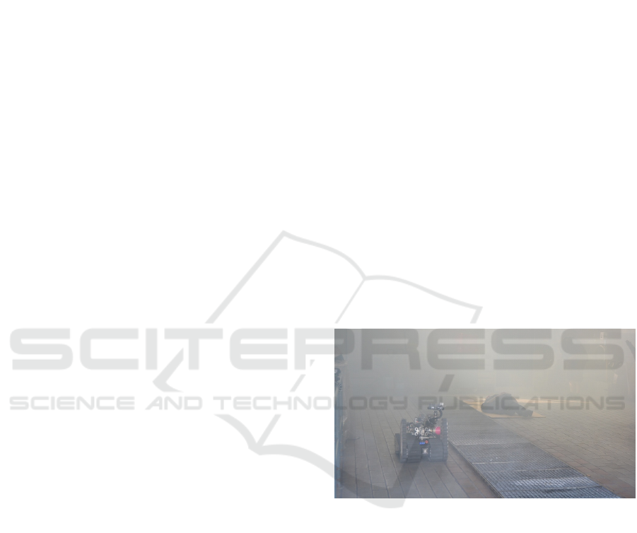
So far a laser scanner and a thermal camera are
used on the rescue robot Schroedi. In a fire drill
with the firefighters in Nuremberg, Germany, it was
demonstrated how victims could be found with the
help of Schroedi (see Figure 1). At present, Schroedi
can be steered into a room filled with smoke by a hu-
man and the victim detection is based on the opera-
tor’s perception of the thermal images. For a human
the detection of victims within an image is intuitive.
If a robot had to detect the exact position and orienta-
tion of a possible victim, the operation becomes more
complicated.
As part of a stationary test, sensor data was taken
with a laser scanner, a thermal camera and a SWIR
camera. The result is displayed within Figure 2 show-
ing a human sitting within a room. A human is ca-
pable of identifying the human’s position within the
Figure 1: Rescue robot Schroedi at a fire drill (Source: A.
Bergmeister).
map (red circle) by eye. The robot needs to be taught
to automatically combine the different data types and
understand the information.
The aim of this project is to implement the first
part of the sensor fusion system, fusing a thermal
camera with a laser scanner. Later on the laser scanner
can be replaced by a radar sensor such that a robot is
capable of detecting victims in a poor visibility situa-
tion such as a house fire. This requires the calibration
of the thermal camera with a 2D laser scanner. The
difficulty is that distance data (3D data) has to be pro-
jected onto the 2D image plane of the thermal camera
image.
This paper is structured as follows: section 2 in-
troduces existing calibration methods, section 3 de-
398
Gleichauf, J., Pfitzner, C. and May, S.
Sensor Fusion of a 2D Laser Scanner and a Thermal Camera.
DOI: 10.5220/0006397303980405
In Proceedings of the 14th International Conference on Informatics in Control, Automation and Robotics (ICINCO 2017) - Volume 1, pages 398-405
ISBN: 978-989-758-263-9
Copyright © 2017 by SCITEPRESS – Science and Technology Publications, Lda. All rights reserved
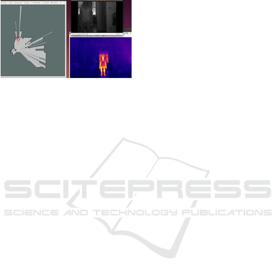
Figure 2: Laser scan map, thermal and SWIR image.
scribes the new approach and finally the conclusion
and future work can be found in chapter 4.
2 STATE OF THE ART
Sensor fusion between several sensors is popular in
robotics. Approaches of fusing a laser scanner with
a thermal camera to combine the advantages of dis-
tance measurements and image information have been
made. Most of these methods use a 3D laser scanner
instead of a 2D one. Approaches combining an RGB
camera with a 2D laser scanner are mentioned in this
chapter, too, as the underlying method would be sim-
ilar for an infrared camera.
2.1 Fusion of a Thermal Camera with a
3D Laser Scanner
In his Bachelor thesis Tom-Marvin Liebelt describes
the sensor fusion between a 3D laser scanner (a ro-
tated SICK LMS100 2D scanner) and a thermal cam-
era. Both sensors are placed in a fixed position such
that the z-axis of the camera lies on the scan plane
of the laser scanner. Different types of calibration
patterns (a printed pattern, a pattern using light bulbs
and one using resistance wire) were compared in this
project. It was decided to use resistance wire which
delivers good thermal images and allows the resulting
pattern to be used for both the intrinsic and extrinsic
calibration. (Liebelt, 2013)
As part of the Smokebot project the calibration
and fusion between a far infrared camera and a 3D
laser scanner were performed. Their calibration pat-
tern is of trihedral shape such that its edges can be
clearly seen within the laser point cloud. (Zeise,
2016)
2.2 Fusion of a Thermal Camera with a
2D Laser Scanner
An approach using an infrared camera is used for fast
moving object detection. The extrinsic calibration
between the two sensors is not precise. Zeng et al.
(2015) approximated the extrinsic transformation by
finding agreement between the horizontal axes. The
difference in the vertical axis (i.e., z) was then mea-
sured manually. For their project this low precision
calibration was sufficient to be able to locate the Re-
gion of Interest (ROI).
2.3 Fusion of a Camera with a 3D Laser
Scanner
Several fusion applications can be found using dif-
ferent types of cameras and a 3D laser scanner. Un-
nikrishnan et al. (2005) introduce the usage of a
Laser-Camera Calibration Toolbox, based on a Mat-
lab graphical user interface. Their calibration pattern
is a leaning chessboard.
For mapping infrared data onto a terrestrial laser
scanner for 3D models of buildings a ”bi-camera” sys-
tem made up of a thermal camera and a RGB cam-
era was created. The aim is to overcome drawbacks
such as time consuming methods caused by classic
approaches where direct registration between the ther-
mal camera and the 3D laser scanner is taking place
using space resection or homography. Furthermore
a low-cost NIR camera is integrated into the system.
For the calibration between the ”bi-camera” system
and the 3D laser scanner, the recognition of common
features between RGB images and the laser intensity
is suggested as in (Meierhold et al., 2010) (this is a
manual task if no targets are used). (Alba et al., 2011)
A similar work was proposed by Borrmann et al.
(2013) with the exceptions that calibration patterns
are used, a printed chessboard pattern for the optical
camera and attached lightbulbs for the infrared cam-
era. The position of the points within these patterns
needs to be detected within the laser scan.
An arbitrary trihedron can be used as calibration
pattern, too. The calibration is based on a non linear
least square problem formulated in terms of geometric
constraints. (Gong et al., 2013)
Pandey et al. (2010) fuse a 3D laser scanner with
an omnidirectional camera. Their calibration method
is based on the approach introduced by Zhang (see
below), with the difference of using an omnidirec-
tional camera instead of a classical camera. A pla-
nar checkerboard pattern is required and needs to be
observed from both, the laser scanner and the camera
system from at least three points of view.
Sensor Fusion of a 2D Laser Scanner and a Thermal Camera
399
2.4 Extrinsic Calibration of a Camera
with a 2D Laser Scanner
Within the research area of pedestrian detection a 2D
laser scanner and a Far Infrared camera are fused. The
calibration is based on the least mean square (LMS)
algorithm. This algorithm takes a sample sequence
with a single pedestrian such that the person can be
detected within both sensor modalities. The coef-
ficients to convert the coordinates from the camera
to the laser scanner coordinate system is calculated.
(Garcia et al., 2010)
Alternatively there are approaches fusing a stan-
dard camera with a 2D laser scanner using different
calibration patterns.
Wasilewsky and Strauss use a rectangular folded
target with one side being black and the other one
coloured white. This allows a clear differentiation be-
tween the two halfs using the camera. The laser scan-
ner produces a triangular scan line - two lines inter-
secting in one point. Hereby the point of intersection
is clearly visible within the laser scan and the camera
image. (Wasielewski and Strauss, 1995)
Zhang and Pless propose a calibration using a sim-
ple checkerboard and solve all geometric constraints
for the transformation under the assumption that the
laser scan points must lie on the camera (calibration)
plane (Zhang and Pless, 2004). This method is im-
plemented within the automatic matlab tool by Kassir
and Peynot (Kassir and Peynot, 2010).
A further approach uses a black line on a white
sheet as calibration target. A created polynomial sys-
tem is solved and the laserscan point which is normal
to the plane is derived (Naroditsky et al., 2011).
Most of the suggested calibration methods for 2D
laser scanners have disadvantages due to a lack of de-
grees of freedom. Six degrees of freedom (transla-
tion in X, Y and Z direction and rotation around these
axes) are necessary to exactly determine the extrinsic
transformation.
As described by Dong and Isler for the meth-
ods suggested by Zhang (Zhang and Pless, 2004),
Wasielewski (Wasielewski and Strauss, 1995) and
Naroditsky (Naroditsky et al., 2011) there are miss-
ing degrees of freedom (Dong and Isler, 2016). This
means that either turning or shifting the calibration
target in different directions would still deliver the
same scan points or line even though it has a com-
pletely different position and it should be possible to
distinguish between the scans.
Dong and Isler developed a calibration target
made up of two triangles which are positioned at an
angle of 150
◦
to each other. Using this target for cal-
ibration, all six degrees of freedom are covered. A
complex algorithm using different planes and vectors
solves all constraints for the extrinsic transformation.
(Dong and Isler, 2016)
This overview showed that no precise extrinsic
calibration method exists for the fusion of a 2D laser
scanner and a thermal camera. Therefore a new
method has to be introduced. Due to the fact that the
calibration pattern proposed by Dong and Isler covers
all degrees of freedom it was decided to use a simi-
lar calibration target with the difference that it must
be visible for the thermal camera instead of a RGB
camera. This new approach also uses a third sensor to
help with the fusion.
3 APPROACH
The chosen approach will be described in detail in this
chapter. The laser scanner and the thermal camera are
combined with a NoIR camera.
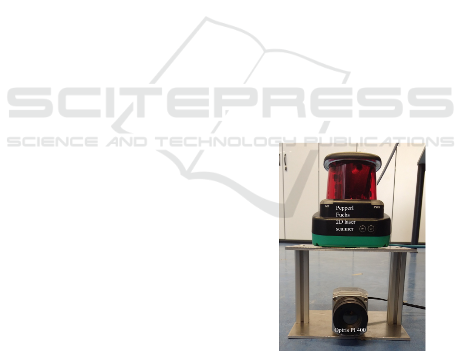
3.1 Sensor Set Up
Both sensors are fixed on top of each other (see Fig-
ure 3). This is necessary to stop a parallax error oc-
curing. Otherwise the sensors would ’look’ sideways
onto each other which leads to an ambiguity. A NoIR
camera is fixed on top of the thermal camera to help
with the calibration and is removed afterwards.
Figure 3: Sensor set up.
The 2D laser scanner in use is the R2000
ODM30M designed by the company Pepperl und
Fuchs. It has a wavelength of 905 nm, a resolution
of 1 mm and an angular resolution of 0,014
◦
. The
ICINCO 2017 - 14th International Conference on Informatics in Control, Automation and Robotics
400

ROS package pepperl fuchs r2000 supplies a driver
for this type of laser scanner. In this project a scan
rate of 50 Hz and 3600 scan samples was chosen. The
laser scanner delivers range and intensity data of the
measurements 360
◦
around itself.
The thermal camera in use is the Optris PI 400. It
has an uncooled detector and delivers a temperature
sensitivity of up to 0.8 K. Its spectral range lies be-
tween 7.5 and 13µm. The ROS package optris drivers
is used as interface for the camera.
Additionaly to the main sensors a Raspberry Pi
camera is applied to help with the calibration between
the laser scanner and the thermal camera. Further
details can be found in the later chapters. The No
Infrared (NoIR) camera (camera module v1) is con-
nected to a Raspberry Pi computer. NoIR implies
the lack of an infrared filter such that infrared light
can be detected. This camera is capable of seeing the
laser scan line. The Raspberry Pi runs with the 16.04
Ubuntu mate version. The ROS package raspicam is
the driver used to run the camera.
3.2 Intrinsic Calibration of the Thermal
and the NoIR Camera
The ROS package camera calibration is used for the
intrinsic calibration of both the thermal camera and
the NoIR camera. The intrinsic calibration is neces-
sary to rectify the image and to remove distortions.
It relates to the projection of the chip plane onto the
image plane of the camera sensor such that the trans-
formation between the sensor’s pixel coordinates and
the world coordinate frame is given. Both cameras
can be modelled as a pinhole camera represented by
this formula:
u
v
1
=
f
x
0 u
0
0 f
y
v
0
0 0 1
X/Z
Y /Z
1
where (u, v) are the distorted image coordinates, f
x
and f
y
are the focal length, u
0
and v
0
are the coordi-
nates of the center of the camera sensor. X, Y and Z
make up the 3D coordinate within the world coordi-
nate system.
Images of the heated calibration pattern with 9x6
circles with a distance to each other of 3.75 cm are
computed by the calibration tool. The images need to
be taken from all different orientations, distances and
at varying degrees of skewness so that the tangential
and radial distortion coefficients can be precisely cal-
culated. The distortions are removed by applying the
following formula to the pixel coordinates:
u
00
v
00
=
u
0
· k + 2p
1
v
0
+ p
2
· (r
2
+ 2u
02
)
v
0
· k + 2p
1
· (r
2
+ 2v
02
) + p
2
u
0
with
k = (1 + k
1
r
2
+ k
2
r
4
+ k
3
r
6
)
where k
1
, k
2
and k
3
are the radial distortion coeffi-
cients and p
1
and p
2
are the tangential distortion co-
efficients. r is the Euclidean distance of u
0
and v
0
with
u
0
= u − u
0
and v
0
= v − v
0
.
The camera matrix and the distortion factors are saved
within a yaml file which is called by the camera driver
when starting it.
The same calibration target has a black and white
pattern on its backside which delivers a good contrast
for the calibration of the Raspberry Pi camera. The
calibration package camera calibration was installed
and run on the Raspberry Pi itself. The calibration
procedure is the same as for the thermal camera.
3.3 Extrinsic Calibration
A special calibration target was developed for the ex-
trinsic calibration of the laser scanner and the thermal
camera (see Figure 4 left).
The basic principle is based upon the publication of
Dong and Isler (Dong and Isler, 2016). In their pa-
per they describe the extrinsic calibration of a cam-
era and a 2D laser scanner. Their approach allows
a direct calibration covering all six degrees of free-
dom. In their paper two triangles are positioned to
each other at an angle of 150
◦
. When using a thermal
camera instead of an RGB camera the target needs to
be heated so that a clear temperature gradient can be
detected. For this reason two triangular shaped alu-
minium plates were produced. As only the edges of
the triangle are of major interest, two slightly smaller
triangles made of high density fibreboard (HDF), are
placed in front. The whole calibration target is fixed
on a wooden board so that it remains in an angle of
150
◦
, with the two triangles being connected by a
metal hinge.
The first test to check whether useful images and
sensor data can be generated was done by heating the
target with a hot air blower. The calibration target was
clearly visible in all different sensor images. Surpris-
ingly the edges of the aluminium triangles were not
visible within the thermal image. It became apparent
that the aluminium cools down much faster than the
HDF boards so that the whole wooden plane was ac-
tually visible within the thermal image (see Figure 4
middle). For this reason the calibration target had to
be adjusted. So far the aluminium was forming the
edges of the triangular target. As the aluminium is
not visible, the wooden triangles were moved towards
the middle, so that the middle edge is visible.
In order to calculate the extrinsic transformation
including translation and rotation between one laser
Sensor Fusion of a 2D Laser Scanner and a Thermal Camera
401
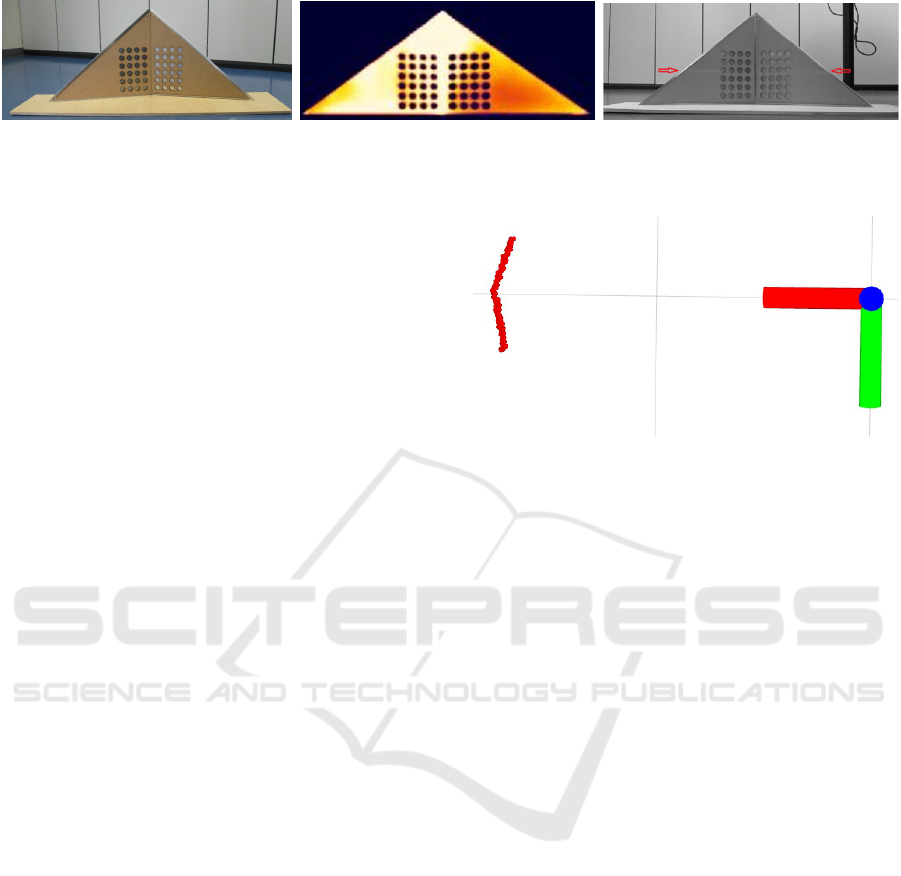
Figure 4: Special calibration target (le.), Calibration target within thermal camera image (mid.) and Laser scan line within
NoIR image (ri.).
scan point and one thermal image pixel, the following
steps had to be followed.
The intersection points between the scan line and
the edges of the triangle need to be identified in both
the laser scan data and the thermal camera image. The
laser scan data needs to be filtered so that only the
scan points displaying the calibration target remain.
Furthermore reflections caused by the laser scan line
interfering with the target’s edges need to be removed.
The scan points belonging to the calibration target’s
edges need to be detected. The Raspberry Pi camera
without an infrared filter, helps to detect the actual
laser scan line (see Figure 4 right). First the trans-
formation between the NoIR image and the thermal
camera image needs to be calculated using the trian-
gle corner coordinates within both images. The next
step is to find the corresponding pixels within the ther-
mal image by applying the transformation on the in-
tersection points within the NoIR image such that they
are given within the thermal camera image. Once the
scan points and the thermal image points of the inter-
section are known, they need to be inserted into an
algorithm which calculates the extrinsic transforma-
tion out of them. The used function is the SolvePnP
function by OpenCV.
3.3.1 Laser Data
The laser scan data holds all measurements which
are placed 360
◦
around the scanner with a maximum
range of 100 m. For the calibration only measure-
ments corresponding to the calibration target are re-
quired - the triangular line within Figure 5 - that is
why filtering is needed. The colourful axes represent
the laser scanner.
Only angles between -31 and 31
◦
within the laser scan
data are accepted. This is because the thermal camera
only has a field of view of 62
◦
. A distance filter is
applied, too, such that all distances further and closer
than the calibration target are eliminated. Artefacts
caused by reflections at the edges of the object are
filtered out by comparing the distances to the neigh-
bours. If they exceed a threshold value, the laser scan
is set to ”not a number”. Additionally only scans
of a certain intensity are accepted. The laser scans
Figure 5: Relevant laser data.
are furthermore converted to 3D-coordinates as the
solvePnP function needs the objectPoints in this for-
mat. As last step the search for the edge scan points is
implemented so that the relevant values are returned.
The edge point in the middle is the laser scan value
with the greatest distance, if the target is positioned
such as within Figure 5. The outer intersection points
are the first and the last point within the scan.
3.3.2 Raspberry PI Camera Data
The pixel coordinates of the wooden triangles need to
be found within both the Raspberry Pi camera image
and the thermal camera image. As the NoIR image
was taken in complete darkness so that the laser scan
line appears brighter, histogram equalisation is neces-
sary.
First of all image processing methods were con-
sidered to segment the laser scan line within the im-
age. The image was supposed to be binarised at first
after which an appropriate threshold was to be found
so only the scan line remains. As the laser scan line is
broad due to the distance from which the image was
taken this was not possible. So even when applying
the Canny operator to detect the edges or different im-
plementations of a thinning algorithm by Zhang and
Suen, no suitable result was gained. Another option
would be the Hough Transform which detects lines
within images. Unfortunately the laser scan line is not
a constant line because of the laser cut holes within
the calibration target so that none of the mentioned
approaches led to satisfying extraction.
In the end it was decided to determine the coor-
ICINCO 2017 - 14th International Conference on Informatics in Control, Automation and Robotics
402
dinates of the (wooden) triangle corners as well as
the intersection points with the laser scan line manu-
ally using OpenCV3. The triangle corner coordinates
were found within the thermal camera image and the
NoIR image. One frame of the recorded bagfile is
used and by drawing in lines around the triangular
shape and through the middle of the laser scan line
the significant points are determined and the correct-
ness is checked at the same time. The intersection
points with the laser scan line were determined within
the NoIR image, too. The triangle corner coordinates
within both images were used to calculate the trans-
formation between them.
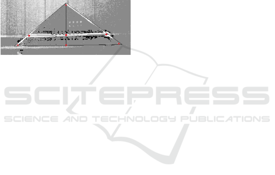
Figure 6: Points selected within the NoIR image.
Four points from both modalities were first selected
and inserted into the function OpenCV findHomogra-
phy . This function is supposed to deliver the transfor-
mation between the thermal and Raspberry Pi camera
image pixels. Unfortunately this function returned an
incorrect transformation matrix so an alternative func-
tion was required. The OpenCV function getAffine-
Transform fulfills this task. This transformation was
applied on the intersection points (transform) such
that they are known within the thermal camera image.
To gain more accuracy this was done for the two sub-
triangles halfs seperately as they correspond to two
different planes.
3.3.3 Calculation of the Extrinsic
Transformation Matrix
To be able to finally calculate the extrinsic transfor-
mation between the laser scanner and the thermal
camera, the laser 3D coordinates and the correspondig
pixel values within the thermal image are both pro-
cessed by the solvePnP function which returns the ro-
tation and the translation as 3x1 vectors.
SolvePnP. Using several corresponding laser and
thermal points, the extrinsic transformation is calcu-
lated using the function solvePnP from OpenCV. This
implementation is based on the publication by Zhang
(Zhang, 2000).
The function estimates the object pose given a set
of 3D laser points (object points) and their corre-
sponding thermal pixels (image projections), taking
the camera matrix and the distortion coefficients into
account. If the points lie on the same plane it inter-
nally calls the function findHomography which finds
the perspective transform between two planes, and re-
fines it by applying Levenberg-Marquardt approxima-
tion, which is an optimisation algorithm based on the
least squares method. If the points lie on different
planes the Direct Linear Transform (DLT) algorithm
is used. It calculates the matrix A which projects the
3D laser points (y
1
,y
2
,y
3
) onto the thermal 2D plane
(x
1
,x
2
) such that:
x
1
x
2
=
a
11
a
12
a
13
a
21
a
22
a
23
y
1
y
2
y
3
The function solvePnP returns the required rotational
and translational vectors which represent the extrinsic
transformation.
In order to apply this transformation on all laserpoints
a reprojection has to take place. This was done manu-
ally at first. In order to get a 4x4 matrix which can be
applied on each laser point coordinate, a rotation ma-
trix was formed using the Rodrigues function. This
function returns a 3x3 rotation matrix. (Rodrigues,
2017) The transformed laser points within the ther-
mal image have the unit m. The conversion to the
pixel value coordinates is done by taking the field of
view (FOV) of the thermal camera into account. The
FOV in the x-direction is of 62
◦
, into the y-direction
the FOV is of 49
◦
. The width and height of the image
in meters depends on the distance the image was taken
from. It turned out that this method lead to erroneous
values so that the more precise function projectPoints
was used instead. This function projects 3D points
onto the image plane.
The transformation is applied to all laserpoints
and projected into the thermal camera image. The
aim is to display the human’s temperature and the dis-
tance to them. The first approach was to find the most
common temperature of the laser scan line and get
the corresponding average distance. Only tempera-
tures within the human’s skin temperature range are
of interest.
Results. The relevant temperature range is made
flexible by finding the maximum temperature value
of the laser scan line. The minimum value is set as
the maximum - 3
◦
C (t
min
= t
max
− 3
◦
C).
The distance found is now the minimum distance
as the closest person has to be found first. This auto-
matically filters out too large values.
The sensors have to be positioned on top of each
other so that no parallax error can occur (see Fig-
ure 3). If the sensors were positioned next to each
Sensor Fusion of a 2D Laser Scanner and a Thermal Camera
403
other they would have different field of views. This
leads to the effect that the thermal camera is looking
sideways onto the laser scan measurements. The par-
allax error has an impact on the short but not long dis-
tances. The results, if the sensors are placed on top of
each other, for the closest values as well as the further
ones are then accurate.
It was also found out that the thermal emission of
the body leads to the effect that the thermal camera
detects pixels with the same temperature even though
they are not part of the body and the laser scanner
returns too long distances. These values need to be
filtered out.
Additionally it has to be made sure that a distance
of at least 35 cm is kept to the sensor system. Other-
wise the laser scan line is not within the measurement
field of the thermal camera. The camera’s optic has to
be taken into account. Half the height of the measure-
ment field has to be greater than the distance between
the laser scanner and the thermal camera in vertical
direction (about 16 cm). Using the optic’s calculator
by optris this leads to a minimum distance of 35 cm.
As final test a person was positioned with differ-
ent distances to the sensor system and the distance
was measured with a reference laser measurement and
with the sensor system. The reference measurement
had an accuracy of 1-2 cm. The data is visualised
within a Bland-Altman plot and shows that with the
exceptance of one outlier the accuracy of the sensor
fusion system is high (see Figure 7).
-0.06
-0.04
-0.02
0
0.02
0 0.5 1 1.5 2 2.5 3 3.5 4 4.5
error in m
distance in m
Figure 7: Bland-Altman plot.
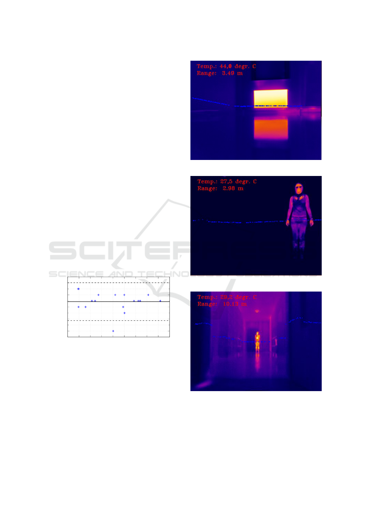
The following images present the results of the sensor
fusion system.
It was found out that the greater the distance the
more inacurrate the calibration. This is due to the res-
olution of the thermal camera. Distances up to 10 m
can be determined with great accuracy. For the in-
tended aim this distance is sufficient as a flat should
not have greater dimensions.
Figure 8: Temperature and distance to a radiator.
Figure 9: Human with a distance of about 3 m.
Figure 10: Human with a distance of about 10 m.
4 CONCLUSIONS
It was shown that it is possible to fuse a 2D laser scan-
ner with a thermal camera using a special triangular
ICINCO 2017 - 14th International Conference on Informatics in Control, Automation and Robotics
404

calibration target and a NoIR camera to help. This
new calibration method covers all six degrees of free-
dom. The sensor set up has to be such that the sensors
are placed on top of each other so that no parallax er-
ror occurs. Furthermore a distance greater than 35 cm
has to be kept to the sensor system. Otherwise the
laser scan line does not lie within the thermal cam-
era measurement field. It was verified that this system
works for distances up to 10 m (see Figure 10).
In the future this system can be improved by using
a thermal camera with a higher resolution. This will
make it applicable for greater distances. Additionally
it can be considered to use image processing and ob-
ject detection algorithms for detecting more than one
person within the image at a time. Furthermore the
existing system can be expanded by a SWIR camera
and a radar sensor to allow localisation under poor
visibility conditions.
REFERENCES
Alba, M. I., Barazzetti, L., Scaioni, M., Rosina, E., and Pre-
vitali, M. (2011). Mapping infrared data on terrestrial
laser scanning 3d models of buildings. Remote Sens-
ing, 3(9):1847.
Borrmann, D., Elseberg, J., and N
¨
uchter, A. (2013). Ther-
mal 3D Mapping of Building Fac¸ades, pages 173–182.
Springer Berlin Heidelberg, Berlin, Heidelberg.
Dong, W. and Isler, V. (2016). A novel method for extrin-
sic calibration of a 2-d laser-rangefinder and a camera.
CoRR, abs/1603.04132.
Garcia, F., Olmeda, D., Armingol, J., and de la Escalera, A.
(2010). Hybrid fusion schemer for pedestrian detec-
tion based on laser scanner and far infrared camera. In
Proceedings of 2010 IEEE Intelligent Vehicles Sympo-
sium, San Diego, USA.
Gong, X., Lin, Y., and Liu, J. (2013). 3d lidar-camera ex-
trinsic calibration using an arbitrary trihedron. Sen-
sors, 13(2):1902.
Kassir, A. and Peynot, T. (2010). Reliable automatic
camera-laser calibration. In Proceedings of Aus-
tralasian Conference on Robotics and Automation,
Brisbane, Australia.
Liebelt, T.-M. (2013). Fusion von 3D-Laserscanner-
Daten mit 2D Thermal-Bilddaten. Bachelor thesis,
Westf
¨
alische Hochschule Gelsenkirchen.
Meierhold, N., Spehr, M., Schilling, A., Gumhold, S., and
Maas, H. (2010). Automatic feature matching be-
tween digital images and 2d representations of a 3d
laser scanner point cloud. International Archives of
Photogrammetry, Remote Sensing and Spatial Infor-
mation Science, Newcastle upon Tyne, UK, 38:446–
451.
Naroditsky, O., Patterson, A., and Daniilidis, K. (2011).
Automatic alignment of a camera with a line scan
lidar system. In Proceedings of 2011 IEEE In-
ternational Conference on Robotics and Automation
(ICRA), Shanghai, China, pages 3429–3434.
Pandey, G., McBride, J., Savarese, S., and Eustice, R.
(2010). Extrinsic calibration of a 3d laser scanner and
an omnidirectional camera. IFAC Proceedings Vol-
umes, Lecce, Italy, 43(16):336 – 341.
Rodrigues (2017). Rodrigus. http://docs.opencv.org/2.4/
modules/calib3d/doc/camera calibration and 3d
reconstruction.html#rodrigues. Accessed on 04 May
2017.
Unnikrishnan, R. and Hebert, M. (2005). Fast extrinsic cal-
ibration of a laser rangefinder to a camera. Technical
Report CMU-RI-TR-05-09, Robotics Institute, Pitts-
burgh, PA.
Wagner, M., Heß, P., Reitelsh
¨
ofer, S., and Franke, J. (2015).
Data fusion between a 2d laser profile sensor and a
camera. In Proceedings of 12th International Con-
ference on Informatics in Control, Automation and
Robotics (ICINCO), 2015, Colmar, Alsace, France,
volume 02, pages 159–165.
Wasielewski, S. and Strauss, O. (1995). Calibration of a
multi-sensor system laser rangefinder / camera. In
Proceedings of the IEEE Xplore Conference: Intelli-
gent Vehicles ’95 Symposium., Detroit, USA.
Zeise, B. (2016). Smokebot deliverable 3.2: Software
toolkit indoor surface temperature mapping. http://
aass.oru.se/Research/mro/smokebot/deliverables/
SmokeBot D3 2.pdf. Accessed on 14 November
2016.
Zeng, L., Ding, M., Zhang, T., and Sun, Z. (2015). A
fast moving object detection method based on 2d laser
scanner and infrared camera. In Proceedings of SPIE
9675, AOPC 2015: Image Processing and Analysis,
Beijing, China.
Zhang, Q. and Pless, R. (2004). Extrinsic calibration of a
camera and laser range finder (improves camera cal-
ibration). In Proceedings of IEEE/RSJ International
Conference on Intelligent Robots and Systems, 2004.
(IROS 2004), Sendai, Japan.
Zhang, Z. (2000). A flexible new technique for camera cali-
bration. In Proceedings of IEEE Transactions on Pat-
tern Analysis and Machine Intelligence, volume 22,
page 13301334.
Sensor Fusion of a 2D Laser Scanner and a Thermal Camera
405
