
A Domain Specific Language for Robot Programming
in the Wood Industry
A Practical Example
V
´
ıctor Juan Exp
´
osito Jim
´
enez and Herwig Zeiner
DIGITAL – Institute for Information and Communication Technologies,
JOANNEUM RESEARCH Forschungsgesellschaft mbH, Steyrergasse, Graz, Austria
Keywords:
Domain Specific Language, Functional Programming, F#, Wood Industry, Robotics.
Abstract:
Domain Specific Languages (DSL) are being used in several fields of industry. This paper shows how a DSL
can be used in the wood industry, automizing some tasks through the use of robots. In this paper we also
implement a syntax to define robot instructions inside a high-level abstraction layer to simplify these instruc-
tions and to develop a reliable tool for developers in order to avoid errors and allow for faster development.
This paper also covers considerations on how to choose the kind of DSL that best fulfills our requirements and
provides an example described in detail.
1 INTRODUCTION
Software development is causing large costs for the
manufacturers and integrators of robot technology.
Often, the volume and risk associated with software
for a new robot system exceeds the expertise and re-
sources of potential adopters in the wood manufactur-
ing industry. This might be mitigated by standardized
and reusable components or easily usable program-
ming tools for domain experts. Such a development
would help to reduce both risks and costs through co-
operative software engineering.
Current research work, especially within the sec-
tor of industrial robotics, is investigating new pro-
gramming methods for making complex tasks eas-
ier to program for standard industrial robots. Com-
mon approaches include complex offline program-
ming methods with a complete 3D model of the robot
cell and the immediate surroundings for a manual
configuration of movement and the handling of tasks.
This requires the programming of specific knowledge
and is customarily done by specialized programmers.
As a consequence, it becomes difficult to change
programs for new tasks based on new requirements,
which is needed for handling tasks with small batch
sizes.
Domain-specific modeling is used in robotics to
describe items with concepts and notations in order
to get closer to the respective domain and to raise the
level of abstraction. This results in models of the sys-
tem or parts of the system which are easier to under-
stand and to validate and in turn lowers the bar for the
skills needed to handle the system’s complexity. It
also helps increase the level of automation and makes
it easier to analyze the system. In this paper, we in-
troduce a new DSL specifically focused on the wood
industry so the advantages of this kind of program-
ming methodology can be applied here as well.
The next section gives an overview of existing and
related work in the field of DSL in the robotics field.
Section 3 explains why a DSL has been implemented
in our scenario and explains the different type of DSL
that are available to choose from. The implementation
of our solution in Section 4 explains the DSL con-
siderations and gives an example. Finally, Section 5
presents the conclusion and the future plans for this
work.
2 RELATED WORK
The implementation of Domain-Specific Modeling
and Languages is a topic which has been widely re-
searched in software development the last few years.
A good starting point for this research is this sur-
vey (Nordmann et al., 2016) in which a general
overview about tools and implementation in robotic
systems can be found. An example of a DSL usage
is given in (Thomas et al., 2013) which describes
a robot programming language using UML/P State-
charts. The work proposes a Domain Specific Lan-
guage (DSL) based on UML Statecharts. This lan-
Jiménez, V. and Zeiner, H.
A Domain Specific Language for Robot Programming in the Wood Industry - A Practical Example.
DOI: 10.5220/0006397205490555
In Proceedings of the 14th International Conference on Informatics in Control, Automation and Robotics (ICINCO 2017) - Volume 2, pages 549-555
ISBN: Not Available
Copyright © 2017 by SCITEPRESS – Science and Technology Publications, Lda. All rights reserved
549

guage is divided into three abstraction layers - pro-
cess, task, and skill. The process layer is intended
for users whose knowledge about programming lan-
guages is limited. The task level involves simple in-
structions for the robot. Finally, the skill level is the
lowest one, describing primitive actions for the robot.
All components that shape the DSL are modeled by
using UML diagrams. The paper also demonstrates
its implementation through a small screw example
that will be extended in future research. (Joyeux and
Albiez, 2011) explain the process of designing an Au-
tonomous Underwater Vehicle (AUV) robot. It starts
by explaining the advantages of using an embedded
DSL on this kind of system. It also presents an ex-
ample based on Ruby that details the implementation
of the system by using Rock and Orocos Real-Time
Toolkit (RTT). Another interesting use case is de-
scribed in (Maro et al., 2015), in which the implemen-
tation of both textual and graphical DSL is described,
as well as the challenges that they have solved.
One of the problems in robot programming is ex-
plained in (Herrero et al., 2015), which clarifies that
the existence of several proprietary languages renders
difficult the task of robot programming. The authors
also present a more generic architecture based on the
robotics skills. These skills could be defined as small
tasks that are a combination of primitives, while prim-
itives are the basic functions that the robot is able to
do. It also explains how the robot in question has been
modeled by using this skill based architecture and the
tests in a real environment.
Moreover, there are several research papers where
a DSL in robotic systems is used to model the sys-
tem. (Lotz et al., 2016) explains the whole process
of a robot modeling system. Meta-model, DSL, and
code generation are explained, within the tools and
framework that the authors have used for each pur-
pose. Graphical and textual representations are used
to show the advantages and disadvantages in each sit-
uation. The paper (Ramaswamy et al., 2014) talks
about SafeRobots, a Model-Driven Software Devel-
opment approach. Its framework is divided into
three parts; the Operational space, the solution space
and the problem space. The operational space col-
lects extended information about system’s analysis.
The workflow of the SafeRobots framework consists
of four parts: General Domain Knowledge Model-
ing, Problem-specific knowledge or solution model-
ing, Problem-specific concrete or operation modeling,
and executable code. The solution model is based
on functional and non-functional properties (NFPs).
These are modeled by using the DSL, Solution Space
Modeling Language (SSML). Another example can
be found in (Schlegel et al., 2009) in which another
model for robot systems is described by trying to use
existing technology to simplify the robot modeling. A
runtime can be found in (Lotz et al., 2011) to moni-
tor the robotics software components. It receives any
information from the sensors and forwards it to the
diagnose port. The black port enriches the informa-
tion it receives, i.e. adding timestamps, and thanks
to a buffer is also able to manage multiple sensors.
Finally, the diagnose port checks whether all loaded
conditions in the XML profiles are valid according the
robot model.
3 DOMAIN SPECIFIC
LANGUAGES
According to the work of (van Deursen et al., 2000), a
Domain Specific Language (DSL) is defined as a pro-
gramming language or executable specification lan-
guage that offers, through appropriate notations and
abstractions, expressive power focused on, and usu-
ally restricted to, a particular problem domain. These
abstractions and notations have to be suitable for the
stakeholders who specify the system. In most situa-
tions, the DSL are focused on limited cases and are
used as a tool for particular processes. In contrast to a
General-purpose Programming Language (GPL) such
as C# or Java, a DSL usually contains only a restricted
set of notations and abstractions specialized to one or
more particular domains.
The main goal of using a DSL is the simplifica-
tion of the development process in which a developer
does not handle complicated functions or parameters.
A DSL can also make a program easier to understand
because it usually presents a human-readable aspect.
Two well-known examples are the Cascading Style
Sheets (CSS) and Structured Query Language (SQL)
languages, which provide an abstraction layer to ease
the development instead of programming in the na-
tive language. There is also a possibility that a project
might use several DSL in various places.
There are mainly two kinds of DSL, textual and
graphical. Both implementations have their own ad-
vantages and disadvantages. A graphical DSL pro-
vides a better visualization and understanding of both
the modeling process and the final model. Unfortu-
nately, versioning is harder to implement for this no-
tation and it can occur that not all situations can be
shown when the system gets too complex.
On the other hand, textual representation increases
the speed of creation and editing but it could be harder
to understand the whole picture of the final system.
Two different types of textual DSL exist; external
DSL, which define their own syntax and semantics,
ICINCO 2017 - 14th International Conference on Informatics in Control, Automation and Robotics
550

and internal DSL, which are embedded in an extensi-
ble GPL. Both extend the syntax and potentially the
semantics of the host language with domain-specific
notations and abstractions.
For external DSL, a translator is needed to convert
the DSL syntax into the host language whose code
can be executed. Most of the frameworks, such as
Xtext
1
or Visual Studio DSL SDK
2
, are able to trans-
late the DSL into a GPL, which will be used for the
implementation of the DSL. Internal DSL use a base
language, such as Lisp, F# or Haskell, to implement a
simplified abstraction for a specific domain based on
the syntax of the host language. Internal DSL are also
called embedded DSL.
In order to efficiently implement and apply a DSL
approach for the development of systems and to fully
exploit its benefits, DSL are typically used in tools
tailored to model-driven development such as the
Eclipse Modeling Project
3
or JetBrains MPS
4
. Mar-
tin Fowler (Fowler, 2010) called these language work-
benches; they offer extensive support for the develop-
ment of DSL. Domain-specific modeling languages
are themselves often modeled using the elements and
following the rules of meta-model languages. The
alternative to the use of a potentially complex meta-
model language available in a language workbench is
the use of a grammar specification formalism, which
can be used by parser generators. However, language
workbenches provide further benefits beyond the def-
inition of an abstract and concrete syntax, such as the
support for the development of textual and/or graph-
ical editors with rich code completion and dynamic
constraint checking at design time that improves the
usability for language users. Furthermore, these en-
vironments provide extension points to plug-in the
required model-to-model (M2M) and model-to-text
(M2T) transformations in order to generate a textual
representation different from system models that inte-
grate with the overall environment used for the devel-
opment of an application.
One of the main parts of designing a DSL is the
modeling of the system. A graphical model typically
provides its own custom graphic syntax, which con-
forms to a custom meta-model and requires a cus-
tomized framework for the editing and can be trans-
formed directly to allow the execution on a target plat-
form or its interpretation. It is also often used for sys-
tem analysis. Here, model checking and validation,
the setup and analysis of simulations or model-based
testing are typical tasks that can be addressed. Be-
1
http://www.eclipse.org/Xtext/
2
https://msdn.microsoft.com/en-us/library/bb126259.aspx
3
https://eclipse.org/modeling/
4
https://www.jetbrains.com/mps/
yond execution and analysis, models are often directly
suitable as documentation but can also be used to gen-
erate further visualization. Further concerns that are
highly relevant for potential DSL users are the kind of
artifacts such as source code, configuration files, etc.
that are provided for a model-based development ap-
proach and how these artifacts are used within a target
platform.
Once the modeling of the software system is com-
plete, the model has to be adapted from a generic to
a specific domain. In this part, two domain imple-
mentations have to be included, the Platform Indepen-
dent Model (PIM) and the Platform Specific Model
(PSM). The first one includes general tasks that can
be reused in other similar environments. This model
is conceived by the robotics experts who are focusing
on the functional part of the components. The PSM
includes the software functions or hardware specifica-
tions which will be used in a concrete platform or do-
main. Application experts are in charge of this model;
they have to adjust and select components as well as
the system configuration according to the PIM.
4 IMPLEMENTATION
The usage of robots in factories is a key point in the
so called Industry 4.0 or Industrial Internet of Things.
This is also a reason why more workers have to learn
how a robot should be managed to carry a task out.
The motivation behind this paper is the development
of a tool that can be used to simplify the implemen-
tation of robots for employees who have limited pro-
gramming knowledge. In such cases, the usage of a
full instructions list for the robot programming is not a
good idea because it can complicate the programming
process, while simplifying this process both avoids er-
rors and improves performance. Systems have to be
used not only by domain experts but also by people
who do not fully understand the whole system.
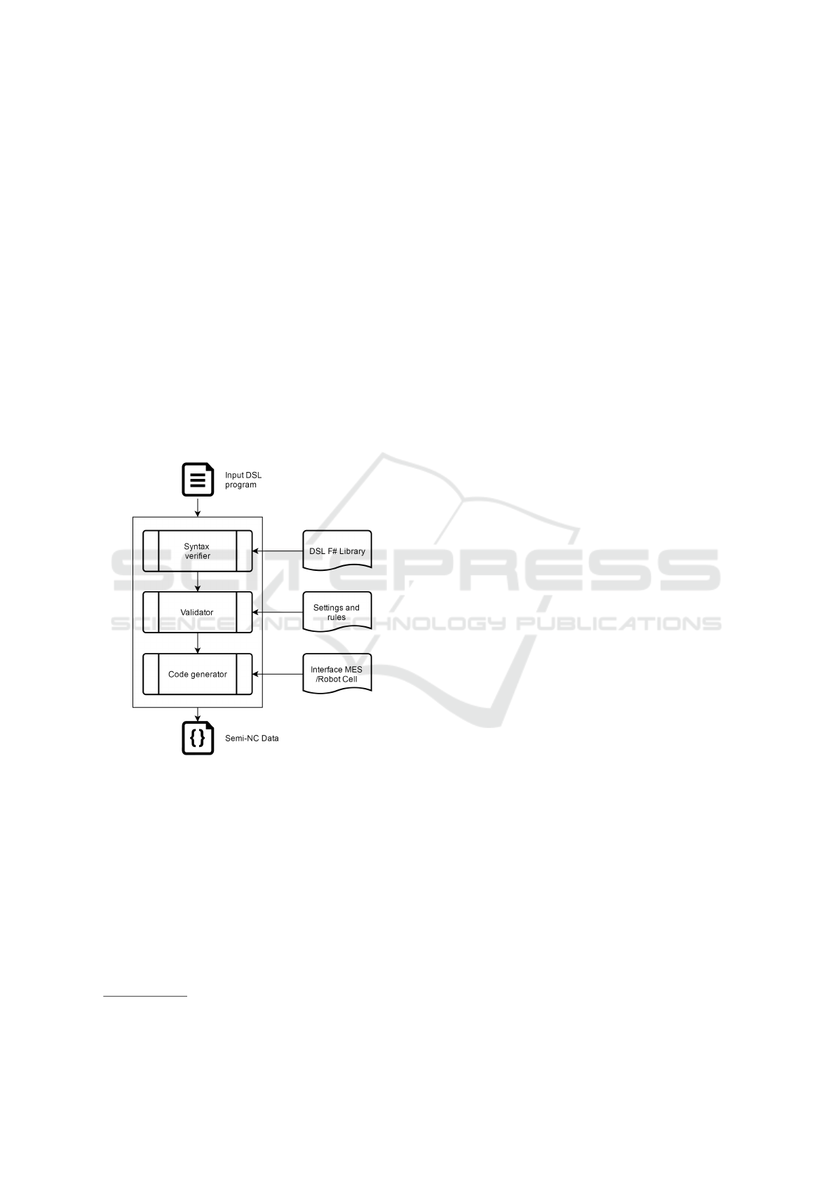
Following the guidelines given in the previous
section, the proposed DSL implementation follows
the structure depicted by Figure 1. In a first step, the
DSL syntax is validated to find if there were some er-
rors when the program was written. Once the syntax
is validated, the DSL checks that the given param-
eters are in the right range by using the predefined
rules and settings. Finally, the code is generated into
a Semi-NC data which will be used in the communi-
cation between the Manufacturing Execution System
(MES) and the robot cell.
Figure 2 depicts the components of our system.
A more detailed description can be found at (Haspl
et al., 2017). Wooden prefabricated walls are manu-
A Domain Specific Language for Robot Programming in the Wood Industry - A Practical Example
551
factured in the assembly line where the robots must be
able to cut, vacuum the remains and staple clamps on
the surface of each wall without human interaction.
There are two ways to interact with the MES; the first
one is by using the CAD file which defines the pieces
and transformations. The needed information is ex-
tracted from the file to generate an output that will be
fed into the MES. Unfortunately, a more detailed ex-
planation of this process is beyond the scope of the
paper. The other possibility is by using the designed
DSL which provides a simple set of instructions to
interact with the MES.
The developed DSL is required to provide workers
an easy interface to manage the system. Once a pro-
gram is written, the interpreter translates this program
into a compatible syntax which will be used for the
MES that handles the communication with the robot
cell. The MES is provided by the company RIB SAA
5
which has designed a specific interface for this pur-
pose.
Figure 1: Structure of the proposed DSL implementation.
4.1 Selection Considerations
The choice of the DSL type has to be decided accord-
ing to our approach on flexibility, adaptation, and in-
tegration. In a first step, a textual implementation was
chosen because it provides better flexibility and inte-
gration as well as a clear human-readable syntax.
One of the main points that have been considered
in choosing the DSL type is the compatibility with
the .NET language stack which is widely used by the
project partners. Therefore, the election of a differ-
ent language stack, such as Java, may present major
5
http://www.saa.at/es/
compatibility issues in a later integration and would
require more maintenance efforts. At this point, the
usage of either an external or an internal DSL was dis-
cussed. Three main options were considered for the
DSL. The first one was to design an external DSL and
then to translate the code to C#. Another possibility
was to use an internal one based on the C# language.
The third one was the implementation of an internal
DSL based on the F# programming language.
For an external DSL, we can set a simple and clear
syntax which can be used within the communication
process of domain experts, while a code generator
must be implemented to translate our syntax into a
program for external DSL. The syntax in this kind of
DSL is a key issue because users have to learn how
the DSL works and its behavior. This means that the
learning curve has to be considered. The most rele-
vant issue in our selection process is the integration
of the DSL in the .NET language stack and its follow-
ing integration in a future platform. For these reasons
we have decided to choose an internal DSL because
we are able to implement our approach in a more af-
fordable way. Therefore, the first option of writing an
external DSL was rejected.
Once an internal DSL is chosen, the election of
F# against C# has some advantages. Functional-
programming languages, like F#, avoid changing-
state and mutable data, meaning that the results of
a functional programming function only depends on
the arguments that are input to the function. There-
fore, a function with the same input arguments al-
ways gives the same result. This kind of language fits
very well for reactive systems, which are the systems
that respond to external events, similar to robots. For
all these aspects, the F# programming language was
chosen to build our DSL. The reason that we use F#
instead of other functional programming languages
such as Lisp or Haskell, is that there is a good integra-
tion available in the .NET runtime stack. F# is fully
supported in Microsoft Visual Studio, which provides
some compatibility with C# and can be used as a li-
brary in C# programs.
4.2 Code Generation and Validation
When a program is written by operators using the
DSL syntax, the validation and code generation
should follow. Here, the program has to be validated
in two aspects, the DSL syntax, and the domain val-
idation. The domain experts carry out this task in
which they have to decide the settings and the limi-
tations of our scenario which will afterwards be in-
cluded in the DSL. For example, developers have to
make sure that the coordinates where the robot arm
ICINCO 2017 - 14th International Conference on Informatics in Control, Automation and Robotics
552
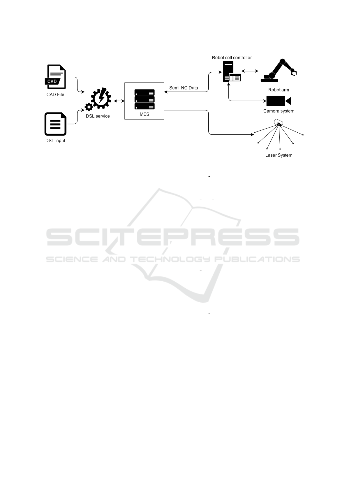
Figure 2: System overview and components interconnection.
would be moving are in reach before the code is gen-
erated. After the program is validated, it will be trans-
lated into a code that is able to be used in the MES
system.
4.3 Example
A small example of the DSL can be found in this sub-
section. For this purpose, the process, in which the
clamps are stapled onto the surface wall, is described.
In this process, the robot arm uses the specific tool to
staple the clamps as can be seen in Figure 3 where
the whole process is shown. This process can also
be described as a combination of high-level buildings
blocks, as listed below:
1. Check security: the robot cell checks that there are
no obstacles which could complicate the process
or put someone in danger.
2. Check positioning: this operation uses the laser to
check that the timber is laid down on the table in
the correct position.
3. Check tool: this operation checks which tool is
currently equipped in the robot to know if the
robot has to switch the tool.
4. Use tool: the robot uses the selected tool to do the
operation.
5. Check operation: there is a camera system which
checks the set clamp. The location and the quality
of the staple process are verified. The camera is
able to perceive the surface of the wall and the
height of the clamp.
At the same time, the process above can also be
defined as a small set of tasks in which every step
includes predefined settings. If this model is used,
every process is described as below:
• CHECK SECURITY: This operation checks that
there are no objects in the robot cell which could
interfere in the execution of the process.
• USE
EXT PERIPHERALS ”toolName” PARAM-
ETERS ”p1”, ”p2”, ”p3”, : This command uses
external peripherals that can be connected to the
cell to extend the functionality of the system. For
example, a laser has been used to check that the
panels are in the correct position. PARAMETERS
are used to set the behavior controlling how this
added peripheral will work.
• MOVE ARM TO ”x”,”y”,”z”: The command
moves the robot arm to the defined coordinator.
• USE TOOL ”toolName” PARAMETERS ”p1”,
”p2”, ”p3”,...: The robot arm uses its equipped
tool with the provided parameters. Each tool has
its own set of parameters. In this example, the sta-
pler uses two parameters, the coordinates and the
length of the staples.
• CHECK QUALITY ”parametersToCheck” PA-
RAMETERS ”p1”,”p2”, ”p3”...: This operation
checks whether the final process has been success-
fully executed. The parametersToCheck defines
which element will be checked, and the parame-
ters determine the precision of verification.
This way, the process is already in a pseudocode
that is easy to understand. The next step will be the
adaptation of this process to the proposed DSL syn-
tax. Finally, the code would be like below:
process "staple"
task "check security"
use "laser"
parameters "7477;1633,
7522;1633,
7522;1876,
7477;1876"
A Domain Specific Language for Robot Programming in the Wood Industry - A Practical Example
553
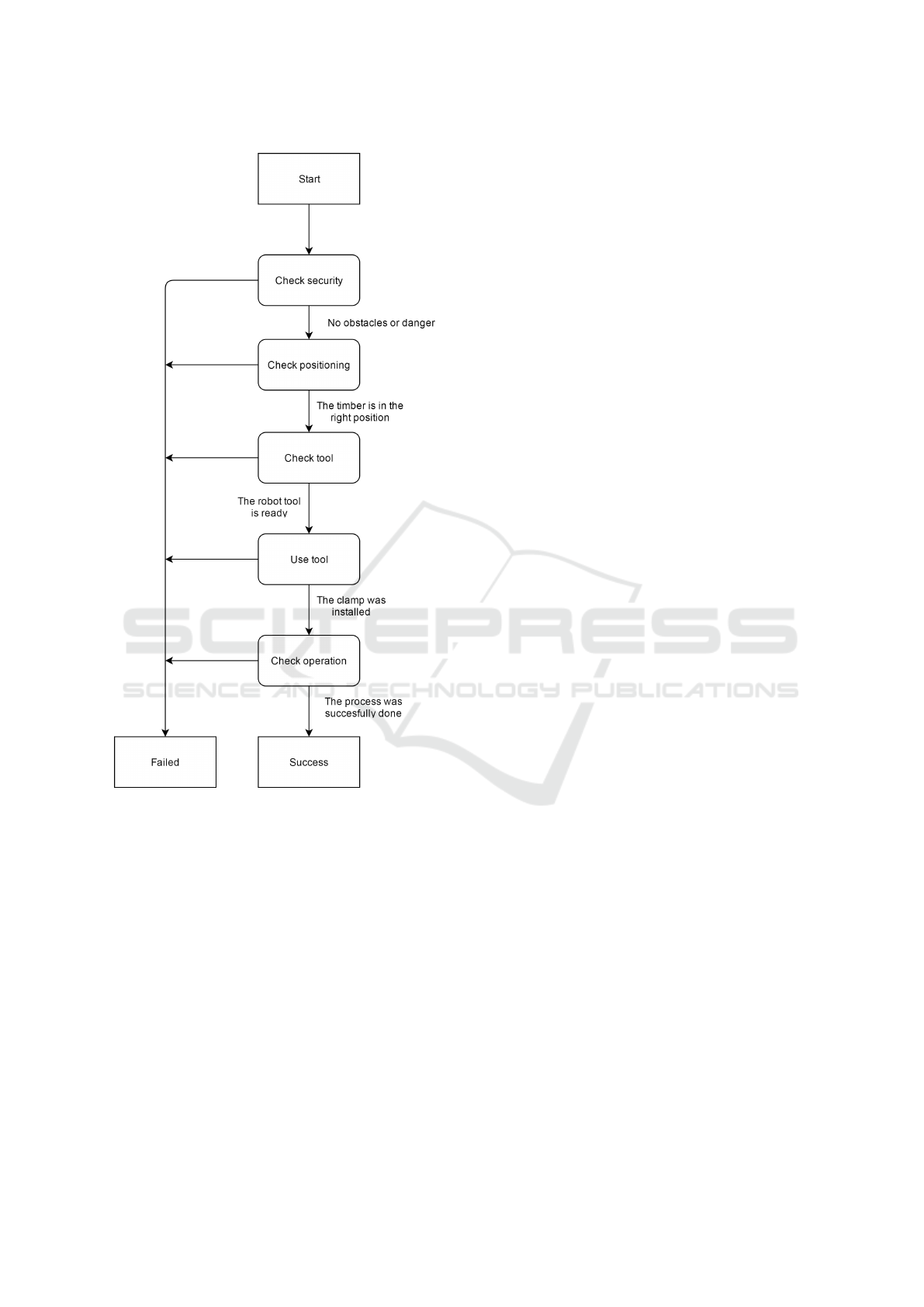
Figure 3: Staple process diagram.
use "arm"
parameters "7477;1683;213"
use "stapler"
parameters "7499,5;1683;213"
task "check quality"
parameters "highPrecision"
The program above shows an easy syntax for the
clamps process. In it, three main instructions can be
explained; process, task and use.
• process: this instruction creates the set of instruc-
tions for the new project . The name of the process
is given as a parameter.
• task: this instruction calls a small task which has
already been modeled in the system.
• use: this instruction is used when a peripheral is
called. Each peripheral includes its own specific
settings. For example, if the robot arm is used, the
parameters are the goal coordinates.
Every program in our DSL begins with a process
instruction which starts and designates the program.
Next, the task security is called, in which the robot
cell is checked to avoid obstacles during the execu-
tion. In the next instruction, the laser tool is used.
This laser checks whether the wood plate is laid down
in the right place. The parameters used for this task
are the coordinates where the plate has to be located.
The coordinates use this syntax:
use "laser"
parameters "minX;minY,
maxX;minY,
maxX;maxY,
maxX;maxY"
All coordinates are given as a double variable
which represents the distance to a reference point
in millimeters. In the next instruction, the robot is
moved to the location defined in the parameter.
use "arm"
parameters "X";"Y";"Z"
The stapler is used to staple the clamp onto the
surface of the plate and, at this point, instead of just
one clamp, a series of clamps, defined by the coordi-
nates, can be stapled.
use "stapler"
parameters "X1;Y1;Z1"
"X2;Y2;Z2"
"X3;Y3;Z3"
To finish the process, the camera checks if all
clamps were successfully stapled. In this instruction,
an optional parameter can be set to define the preci-
sion of the verification.
task "check quality"
parameters "precision"
Once the code is set, the validator checks that ev-
ery task is valid and also that the given parameters of
the tools are correct and in reach. For example, if a
destiny coordinator is not reachable for the robot arm,
a warning message will be sent by the software com-
ponent to notify workers.
As can be seen, we are able to model a process
with a relatively human-readable and minimal syntax.
Thanks to F#, we are able to reach this goal through
simple functions which can be declared for easy use.
5 CONCLUSION
This paper gives an overview of the usage of Domain
Specific Languages (DSL) in robot systems, and ex-
plains the fundamentals of model-driven approaches.
ICINCO 2017 - 14th International Conference on Informatics in Control, Automation and Robotics
554

It also describes the design of a DSL to be used in a
wood factory. The design process was explained in
detail in order to arrive at a DSL that could be used
for the company to model manufacturing processes
with little effort. This is an important issue for work-
ers without profound programming language knowl-
edge, with a minimal and human-readable syntax as
key points. The choice of a DSL based on F# was
made because it fulfilled the requirements of having
a library compatible with the .Net environment, and
it is also a functional-programming language, which
perfectly suits a reactive system like this. This docu-
ment also includes some examples to help understand
how this DSL implementation works.
In our future work, the implementation of this
DSL library in the system will be extended to em-
brace new scenarios in which more complex rules are
needed.
ACKNOWLEDGEMENTS
The RobWood project is partially funded by the Aus-
trian Research Promotion Agency (FFG) and the Aus-
trian Ministry for Transport, Innovation and Technol-
ogy (bmvit).
The authors are grateful to the institutions funding
the RobWood project and wish to thank all project
partners for their contributions.
REFERENCES
Fowler, M. (2010). Domain Specific Languages. Addison-
Wesley Professional, Boston, USA.
Haspl, T., Capovilla, C., Rinnhofer, A., Exp
´
osito Jim
´
enez,
V. J., Maier, S., V
¨
olkl, M., Zarnhofer, M., J
¨
obstl,
R. A., Pretterhofer, E., Dieber, B., and Zeiner, H.
(2017). Robwood - smart robotics for wood industry.
In OAGM and ARW Joint Workshop 2017 on Vision,
Automation and Robotics.
Herrero, H., Outn, J. L., Esnaola, U., Sall, D., and de Ipia,
K. L. (2015). Development and evaluation of a skill
based architecture for applied industrial robotics. In
2015 4th International Work Conference on Bioin-
spired Intelligence (IWOBI), pages 191–196.
Joyeux, S. and Albiez, J. (2011). Robot development: from
components to systems. In 6th National Conference
on Control Architectures of Robots, page 15 p., Greno-
ble, France. INRIA Grenoble Rh
ˆ
one-Alpes.
Lotz, A., Hamann, A., L
¨
utkebohle, I., Stampfer, D., Lutz,
M., and Schlegel, C. (2016). Modeling non-functional
application domain constraints for component-based
robotics software systems. CoRR, abs/1601.02379.
Lotz, A., Steck, A., and Schlegel, C. (2011). Runtime
monitoring of robotics software components: Increas-
ing robustness of service robotic systems. In 2011
15th International Conference on Advanced Robotics
(ICAR), pages 285–290.
Maro, S., Stegh
¨
ofer, J.-P., Anjorin, A., Tichy, M., and Gelin,
L. (2015). On integrating graphical and textual edi-
tors for a uml profile based domain specific language:
An industrial experience. In Proceedings of the 2015
ACM SIGPLAN International Conference on Software
Language Engineering, SLE 2015, pages 1–12, New
York, NY, USA. ACM.
Nordmann, A., Hochgeschwender, N., Wigand, D., and
Wrede, S. (2016). A Survey on Domain-Specific
Modeling and Languages in Robotics. Journal of Soft-
ware Engineering for Robotics (JOSER).
Ramaswamy, A., Monsuez, B., and Tapus, A. (2014). Safer-
obots: A model-driven approach for designing robotic
software architectures. In 2014 International Con-
ference on Collaboration Technologies and Systems
(CTS), pages 131–134.
Schlegel, C., Hassler, T., Lotz, A., and Steck, A. (2009).
Robotic software systems: From code-driven to
model-driven designs. In 2009 International Confer-
ence on Advanced Robotics, pages 1–8.
Thomas, U., Hirzinger, G., Rumpe, B., Schulze, C., and
Wortmann, A. (2013). A new skill based robot pro-
gramming language using uml/p statecharts. In 2013
IEEE International Conference on Robotics and Au-
tomation, pages 461–466.
van Deursen, A., Klint, P., and Visser, J. (2000). Domain-
specific languages: An annotated bibliography. SIG-
PLAN Not., 35(6):26–36.
A Domain Specific Language for Robot Programming in the Wood Industry - A Practical Example
555
