
Design of a Special Lower Limb Rehabilitation Robot for
Leg Patients
Gab-Soon Kim, Han-Sol Kim and Jae-Hyun Jung
Department of Control & Instrumentation Engineering (ERI), Gyeongsang National University,
501 Jinju-Daerop, Jinju, Republic of Korea
Keywords: Rehabilitation Robot, Linear Motion Mechanism, Link, Forward Kinematics, Inverse Kinematics.
Abstract: We describe the design of a special lower limb rehabilitation robot for leg patients and its operation. The
lower limb rehabilitation robot is composed of linear motion mechanisms, links, a foot plate, a joint and
two-axis force sensors. The links and the foot plate are rotated according to the linear motion mechanisms.
The bending motions of the hip, knee, and ankle are performed. The designed rehabilitation robot was
subjected to tests involving hip joint bending, knee joint bending, and ankle joint bending exercises, and the
robot operated smoothly. Therefore, it can be concluded that the designed rehabilitation robot can be used
on leg patients, for the three exercises stated above.
1 INTRODUCTION
They are usually rehabilitated by a professional
therapist while in bed, because leg patients face
difficulties in walking. Lower limb rehabilitation
exercises include bending and stretching the knee
joint, ankle joint, and hip joint. It is very difficult for
a rehabilitation therapist to rehabilitate such patients,
because their legs are heavy. Recently, various
rehabilitation robots have been developed owing to a
dearth of rehabilitation therapists.
Yu, H. designed and controlled a robot capable
of rehabilitating the knee and ankle joints while a
patient walks. The robot is divided into two
actuators, one for the ankle joint and another for the
knee joint. These actuators convert the rotational
motion of the motor into a linear motion and turn it
into a rotational motion using an eccentric disc. This
robot can rotate each joint only when the motor
rotates and the knee joint and the ankle joint can be
rehabilitated. Akdogan, E. designed and controlled a
3-degree-of-freedom therapeutic exercise robot for
lower limb rehabilitation in patients with spine,
stroke, and muscle diseases. The patient is placed in
a chair that allows sitting and lying down. The
rehabilitation treatment of the knee joint is
performed by pushing up and down the calf, and the
rehabilitation of the hip joint is performed by
pushing up and down the thigh. The robot lifts and
lowers the legs by kinematic interpretation, and the
force sensor is attached to a device for pushing up
the calf and thigh, measuring the pushing force,
including the weight of the lower limb. This robot
can only rehabilitate the knee joint and the hip joint,
not being possible to perform rehabilitation
treatment on the ankle joint. Zhang, J. F. conducted
modeling to control a robot along a walking path
when a stroke patient wears a 4-degree-of-freedom
walking assistant robot and performs a walking
exercise. The theoretical position of the knee joint
and of the hip joint was compared with the test
position, and the torque of the hip and knee joints
was measured.
Pennycott, A. performed posture control during a
walking assist robot motion. The robot performs a
walking athletic treatment on a patient who can
walk. Malcolm, P. designed a robot for an
exoskeleton exercise, which uses a linear motion
mechanism mounted on a calf to push and pull the
heel, in order to rotate the ankle joint. This can only
rehabilitate the patient's ankle. Wu, M. designed a
robot that hangs the patient's body vertically, binds
the rope to the lower limb, and performs walking
training, by using the robot's motor and pulley. This
is appropriate for gait training for mild patients and
is not suitable for the rehabilitation of patients with
severe stroke who are lying down. Martins, M. M.
designed a mobile robot, consisting of a body with
three wheels spaced 90 degrees apart and capable of
supporting the patient's arm. This robot can be
walked on while a patient with an uncomfortable leg
Kim, G-S., Kim, H-S. and Jung, J-H.
Design of a Special Lower Limb Rehabilitation Robot for Leg Patients.
DOI: 10.5220/0006391902090215
In Proceedings of the 14th International Conference on Informatics in Control, Automation and Robotics (ICINCO 2017) - Volume 2, pages 209-215
ISBN: Not Available
Copyright © 2017 by SCITEPRESS – Science and Technology Publications, Lda. All rights reserved
209
is supported by the force of his/her arm and
shoulder, and can be used for a patient's gait
rehabilitation. Karavas, N, designed and controlled a
robot for an assisted knee exoskeleton. The robot
was made by connecting two links, such as a link of
a calf part and a link of a thigh part with a joint, and
attaching a motor to the joint part. This robot can
handle the patient's knee joints. Rajasekaran, V.
safely controlled a wearing robot that can apply
rotational force to the ankle joint, knee joint, and hip
joint of a person. The robot can be used to assist
walking by a minor patient, or for ankle
rehabilitation. However, it is not suitable for use in
patients with severe stroke. Mohammeda, S.
performed nonlinear control of a knee joint robot
consisting of a thigh link and a calf link. The robot
can fix the thigh and the calf using an adhesive cloth
and then rehabilitate the knee joint while patient sits
on a chair. Asbeck, A. T. designed a robot for hip
rehabilitation. The robot consists of a device that can
rotate a pulley with a line wound around it and a
device that winds a band around the thigh. The robot
can rotate accurately in the direction of pulling of
the string and can also rotate the hip joint backward
while sensing the force with the force measuring
sensor. However, it cannot rotate in the opposite
direction. The robot already developed is able to
treat only the ankle joint, only the knee joint, and
both the knee joint and the hip joint, while walking
on a patient who can walk. However, severe stroke
patients lie on the bed and the hip, knee joint and
ankle joint cannot be treated at the same time by the
robots that were developed.
In this study, all the links of the designed
rehabilitation robot are constrained to each other,
and the constrained robot is accompanied by errors
such as link length and installation angle due to
machining errors and assembly errors. Therefore, it
is difficult to control the angle of rotation of the
motor by the inverse kinematic analysis.
Consequently, it is difficult to precisely control the
robot presented in this paper, because of position
control. Due to this, we intend to perform force
control for the basic operation. In order to perform
force control, a force sensor must be attached to the
link of the robot. Nagai, K. al. developed the multi-
axial force sensors until now, which measure the
force in various directions, mainly include a four-
axis force sensor and a six-axis force sensor. These
are bulky, difficult to attach, and do not fit the rated
capacity, making them unsuitable for rehabilitation
robots. Therefore, the force sensors of the
rehabilitation robot are designed and manufactured
on the links of the robot.
In this paper, we designed a special lower limb
rehabilitation robot that can treat the hip joint, knee
joint, and ankle joint while patient is lying on the
bed. For this purpose, the body of the lower limb
rehabilitation robot was designed and fabricated, and
tests involving hip joint and knee joint bending
exercises were performed to confirm the operation
of the lower limb rehabilitation robot.
2 DESIGN AND MANUFACTURE
OF THE LOWER LIMB
REHABILITATION ROBOT
2.1 Principle of Lower Limb
Rehabilitation Robot
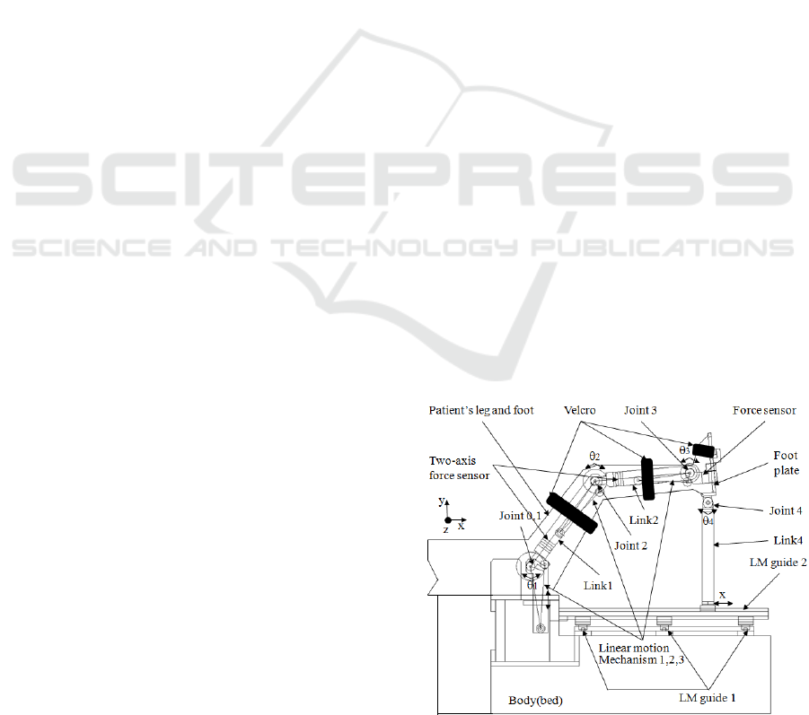
Figure 1 shows the principle of the lower limb
rehabilitation robot, which consists of a body, a
thigh link mechanism, a calf link mechanism, a foot
mechanism. The body consisted of a bed, LM Guide
1, LM Guide 2, and a Hip Motor. The thigh link
mechanism consisted of a linear motion mechanism
1, a joint 1, and a link 1 with a two-axis force sensor.
The calf link mechanism consisted of a linear
motion mechanism 2, a joint 2, and a link 2 with a
two-axis force sensor. The foot mechanism consisted
of a foot plate, an uniaxial force sensor, and link 4.
When rehabilitating the hip, knee, and ankle joints
of leg patients, the patient is first placed on the bed
in, and the patient's thigh, calf, and foot are fixed to
each part of the robot using Velcro, as shown in
Figure 1. Second, when the hip joint bending
exercise is performed, and the linear motion
mechanism 1 is driven, the thigh link mechanism
Figure 1: Principle of lower limb rehabilitation robot.
ICINCO 2017 - 14th International Conference on Informatics in Control, Automation and Robotics
210

makes joint 1 rotate forward and backward at a
rotational angle
1
θ
, and, as a result, each joint angle
2
θ
,
4
θ
is rotated, and link 4 slides in the forward
and backward directions along the LM guide 2.
Third, when the bending knee joint exercise is
performed and the linear motion mechanism 2 is driven,
the calf link mechanism rotates forward and backward
with the rotation angle
2
θ
of joint 2. As a result, each
joint angle
1
θ
,
4
θ
is rotated, and link 4 slides in the
forward and backward directions along the LM guide 2.
Fourth, in the bending motion of the ankle joint, and the
linear motion mechanism 3 is driven, the joint 3 rotates
forward and backward at an angle of rotation
3
θ
. As a
result, each joint angle is rotated, and link 4 slides in the
forward and backward directions along the LM guide 2.
As described above, the lower limb rehabilitation robot
rotates and slides with all links restrained. Such a robot
often fails to operate smoothly due to a fitting
phenomenon originated from a precision machining error
of each mechanism, as well as from a control error of an
assembly error linear motion mechanism. To solve this
problem, force sensors Fy and Fz, which can measure the
force in the y and z directions, respectively, were designed
and fabricated on link 1 and link 2, and an uniaxial force
sensor was designed and fabricated on link 3 (foot plate).
In each rehabilitation exercise, the linear motion
mechanisms 1, 2 and 3 are controlled based on the Fy
force values of link 1, link 2, and link 3, respectively, so
that the links and mechanisms of the robot are smoothly
operated.
2.2 Kinematics Analysis of
Rehabilitation Robot
The rehabilitation exercise using the lower limb
rehabilitation robot should be performed on the hip
joint and on the knee joint simultaneously, and
should be performed separately on the ankle joint.
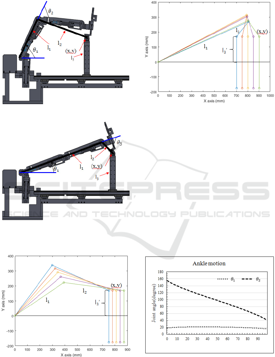
Figure 2 shows a schematic diagram of the
kinematic analysis for the rehabilitation exercise
using the lower limb rehabilitation robot. Figure 2
(a) shows a schematic diagram for the hip and knee
joints rehabilitation exercise. For this exercise, the
ankle joint shown in Figure 1 (joint 3,
3
θ
) should be
fixed, so that it is not allowed to move. Link 4 is
reciprocated in the x-axis, and the actual rotational
movement is only in joint 1 and joint 2. Therefore,
the rotating joints of the lower limb rehabilitation
robot for hip and knee joints rehabilitation
movements are the hip joints (
1
θ
) and the knee
joints (
2
θ
), and the joints of the lower limb
rehabilitation robot for the ankle joint rehabilitation
movements are the hip joints (
1
θ
) and the ankle
joints (
3
θ
).
As the motion of each joint of the lower limb
rehabilitation robot is similar in the two
rehabilitation exercises, the forward kinematic and
the inverse kinematic formulas for the hip joint and
knee joint rehabilitation exercise can also be used on
the ankle joint rehabilitation exercise. In other
words, the equations for the knee joint rehabilitation
exercise can be changed by replacing
2
θ
with
3
θ
in
the equation for the hip and knee joint rehabilitation
exercise.
The forward kinematic equation for hip and knee
joints rehabilitation can be expressed as a matrix of
orientation and position, and the equation can be
written as:
+−−−
+−−−−
=
1000
0100
)(sin)(sin0)(cos)(sin
)(cos)(cos0)(sin)cos(
112122121
112122121
0
3
θθθθθθθ
θθθθθθθ
ll
ll
T
(1)
The forward kinematic equations for x and y of
joint 4 are as follows:
)(cos)(cos
11212
θ
θ
θ
llx +−= (2)
)(sin)(sin
11212
θθθ
lly +−=
To obtain the inverse kinematic equations
1
θ
and
2
θ
, we can use
2
cos
θ
and
2
sin
θ
using x and y in Eq.
(1). The inverse kinematic equations of
2
cos
θ
and
2
sin
θ
are as follows:
21
2
2
2
1
22
2
2
cos
ll
llyx +−+
=
θ
(3)
2
2
2
cos1sin
θθ
−−=
In addition,
1
cos
θ
and
1
sin
θ
can be derived by
using x and y in eq. (1). They are as follows:
2
22
2
221
22221
1
)sin()cos(
sin)cos(
cos
θθ
θθ
θ
lll
ylxll
++
++
=
(4)
2
22
2
221
22221
1
)sin()cos(
sin)cos(
sin
θθ
θθ
θ
lll
xlyll
++
−+
=
The inverse kinematic equations
1
θ
and
2
θ
are
as follows:
2
2
1
2
cos
sin
tan
θ
θ
θ
−
=
(5)
1
1
1
1
cos
sin
tan
θ
θ
θ
−
=
Design of a Special Lower Limb Rehabilitation Robot for Leg Patients
211
(a) Hip and knee joint rehabilitation exercise.
(b) Ankle joint rehabilitation exercise.
Figure 2: Schematic of forward kinematics and inverse
kinematics.
(a) Hip and knee joint rehabilitation exercise.
(b) Ankle joint rehabilitation exercise.
Figure 3: Graph of kinematic analysis.
Figure 3 (a) shows the results of the simulation
using the forward kinematic equation (2) for the hip
and knee joint rehabilitation exercise. The length of
each link,
mml 450
1
=
,
mml 483
2
=
, and
mml 169
3
=
was obtained by substituting y=169 mm,
rotation angle
1
θ
(48.64268°~29.64264°), and knee
joint rotation angle
2
θ
(69.0903°~36.01507°) into
the forward kinematic equation (2). Figure 3 (b)
shows the results of the simulation using the forward
kinematic equation (2) for the ankle joint
rehabilitation exercise. The length of each link,
mml 850
1
=
,
mml 146
2
=
, and
mml 169
3
=
was
obtained by substituting y=169 mm, rotation angle
1
θ
(18.4956°~21.7367°), and knee joint rotation
angle
2
θ
(155.0053°~66.7051°) into the forward
(a) Hip and knee joint rehabilitation exercise.
Figure 4: Graph of inverse kinematic analysis.
ICINCO 2017 - 14th International Conference on Informatics in Control, Automation and Robotics
212
(b) Ankle joint rehabilitation exercise.
Figure 4: Graph of inverse kinematic analysis (cont.).
kinematic equation (2). Figure 4 (a) is a graph
plotted using the inverse kinematic equation (5) for
the hip and knee joint rehabilitation, and Figure 4 (b)
is a graph plotted using the inverse kinematic
equation (5) for ankle joint rehabilitation. In the
rehabilitation robot, three links are constrained, and
as the size of y is vertically constant,
1
θ
and
2
θ
are
obtained according to the change of x. Therefore, x,
1
θ
, and
2
θ
of Figure 3 and Figure 4 are related with
each other.
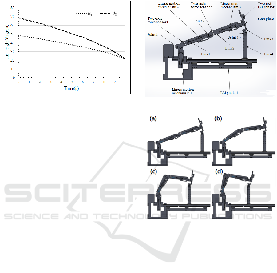
2.3 Design and Simulation of Lower
Limb Rehabilitation Robot
Figure 7 shows the simulation of the lower limb
rehabilitation robot: Figure 7 (a) shows the state of
the lower limb rehabilitation robot, and Figure 7 (b)
shows the simulation of the mechanism for hip joint
exercise and knee joint exercise. Link 1 can be bent
over 80° in relation to the horizontal plane, and link
2 can be bent over 90° in relation to the central line
of link 1. Rotating the hip joint clockwise and the
knee joint counter-clockwise first pushes the linear
motion mechanism 1 and then rotates link 1
clockwise about joint 1. At the same time, the linear
motion mechanism 2 is pulled to rotate link 2
counter-clockwise about the joint 2. Thereafter, joint
4 rotates freely and link 4 moves forward along LM
guide 1. When the hip joint is rotated counter-
clockwise and the knee joint is rotated clockwise,
the operation is reversed. Link 4 is designed to
adjust the height from 340 mm to 500 mm in
relation to the surface of the bed. This is because the
patient feels comfortable at about 340 mm from the
bed surface during the ankle joint bending exercise
and during the knee joint bending exercise.
(a) Lower limb rehabilitation robot.
(b) Motion of hip joint exercise and knee joint bending
exercise.
Figure 5: Simulation of lower limb rehabilitation robot.
2.4 Manufacture of Lower Limb
Rehabilitation Robot
Figure 7 shows the manufactured lower limb
rehabilitation robot, which consists of two
controllers, a left-leg robot mechanism, and a right-
leg robot mechanism. The controller unit consists of
two controllers, one for the left leg robot mechanism
and the other for the right leg robot mechanism. The
purpose of using two controllers is to receive data
from two force sensors on each robotic mechanism
leg, and to operate quickly when controlling four
motors. The lower limb rehabilitation robot consists
of a body, a thigh linkage, a calf linkage, and a
footplate.
Design of a Special Lower Limb Rehabilitation Robot for Leg Patients
213
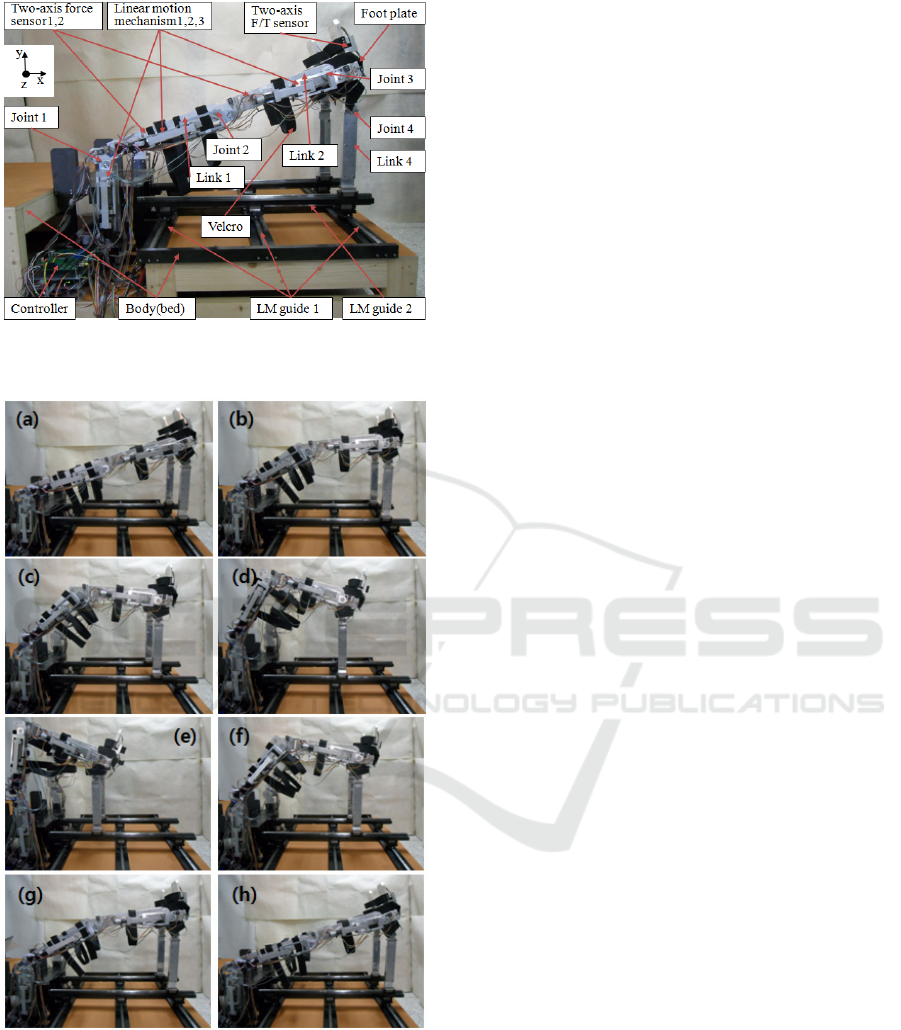
Figure 6: Fabricated lower limb rehabilitation robot for leg
patient.
Figure 7: Hip and knee bending exercises of the lower
limb rehabilitation robot.
The body is a bed that patient can be laid, LMM
1 is used to rotate the thigh link up and down, LM
guide 1 is used when the entire leg moves left and
right during the hip joint exercise, and LM guide 2 is
used to move forward and backward during the knee
joint bending exercise. The thigh link mechanism
includes a LMM 2, that is used to rotate the calf link
up and down, a joint 1 for rotating the thigh link, a
Fy force sensor , a Fz force sensor (two-axis force
sensor) 1. The calf link mechanism includes a LMM
3, that is used to rotate the ankle mechanism, a joint
2 for rotating the calf link, and a link 2, which is
produced by directly processing the Fy force sensor
and the Fz force sensor (two-axis force sensor 2).
The foot mechanism consisted of a foot plate for
fixing the foot, and link 3 and link 4 for rotating the
ankle during the ankle bending exercise. The
operation of the lower limb rehabilitation robot is
such that when LMM 1 is pulled, link 1 rotates in
the clockwise direction based on the joint 1 and
when LMM 1 is pushed in the opposite direction,
link 1 rotates in the counter-clockwise direction.
When LMM 2 is pulled by rotating the motor, link 2
rotates based on the joint 2, and, at the same time,
link 1 rotates in the counter-clockwise direction.
When LMM 3 is pulled by rotating the motor, link 2
rotates in the clockwise direction, based on the
joint 3, and, at the same time, link 1 rotates in the
counter-clockwise direction. When pushed in the
opposite direction, each link rotates in the opposite
direction. At this time, joint 3 freely rotates
clockwise and counter-clockwise, according to the
situation, so that link 4 moves back and forth along
LM guide 1.
Figure 7 shows photographs of the hip and knee
joint bending exercise of the lower limb
rehabilitation robot performed without a person. It
starts from the initial state (Figure 7 (a)), completes
the bending (Figure 7 (b)~(e)), and returns to the
initial state (Figure 7 (f)~(g)).
3 CONCLUSIONS
In this study, we designed a lower limb
rehabilitation robot that can treat the hip joint, knee
joint, and ankle joint while the patient is lying on the
bed. We controlled the robot by force control. We
designed and manufactured the lower limb
rehabilitation robot for stroke patients. The robot
uses the linear motion mechanisms, the links. The
hip and knee bending exercises were performed
normally. To verify the stability of the system, with
the goal of applying the developed rehabilitation
robot, the exercise was performed stably. Therefore,
it can be concluded that the lower limb rehabilitation
robot designed in this study can perform the hip and
knee bending exercise, with leg patients. In future
studies, the designed lower limb rehabilitation robot
ICINCO 2017 - 14th International Conference on Informatics in Control, Automation and Robotics
214

will be used to perform the hip and knee bending
exercise with leg patients.
ACKNOWLEDGEMENTS
This research was supported by Basic Science
Research Program through the National Research
Foundation of Korea (NRF) funded by the
Ministry of Science, ICT and Future Planning
(No. 2015R1A2A2A01002952).
REFERENCES
Yu, H., Huang, S., Chen,G., Thakor, N., 2013, Control
design of a novel compliant actuator for rehabilitation
robots, Mechatronics, No. 23, pp. 1072-1083.
Akdogan, E., Adli, M. A., 2011, The design and control a
therapeutic exercise robot for lower limb
rehabilitation: Physiotherabot, Mechatronics, No.21,
pp. 509-522.
Zhang, J. F., Dong, Y. M., Yang, C. J., Geng, Y., Chen, Y.
Yang, T., 2010, 5-Link model based gait trajectory
adaption control strategies of the gait rehabilitation
exoskeleton for post-stroke patients, Mechatronics,
No. 20, pp. 368-376, 2010.
Pennycott, A., Hunt, K. J., Jack, L. P., Perret, C.,
Kakebeeke, T. H., 2009, Estimation and volitional
feedback control of active work rate during robot-
assisted gait, Control Engineering Pracrice, No. 17,
pp. 322-328.
Malcolm, P., Fiers, P., Segers, V., Caekenberghe, I. V.,
Lenoir, M., Clercq, D. D., 2009, Experimental study
on the role of the ankle push off in the walk-to-run
transition by means of a owered ankle-foot-
exoskeleton, Gait & Posture, No. 30, pp. 322-327.
Wu, M., Hornby, T. G., Landry, J. M., Roth, H., Schmit, B.
D., 2011, A cable-driven locomotor training system
for restoration of gait in human SCI, Gait & Posture,
No. 33, pp. 256-260.
Martins, M. M., Santos, C. P., Anselmo, F. N., Ramon C.,
2012, Assistive mobility devices focusing on Smart
Walkers: Classification and review, Robotics and
Autonomous Systems, No. 60, pp. 548-562.
Karavas, N., Ajoudani, A., Tsagarakis, N., Saglia, J.,
Bicchi, A., Caldwell, D., 2014, Tele-impedance based
assistive control for a compliant knee exoskeleton,
Robotics and Autonomous Systems, Vol. 73, No. 2015,
pp. 78-90.
Rajasekaran, V., Aranda, J., Casals, A., Pons, J. L., 2014,
An adaptive control strategy for postural stability
using a wearable robot, Robotics and Autonomous
Systems, Vol. 73, No. 2015, pp. 16-23.
Mohammeda, S., Huoa, W., Huang, J., Rifai, H., Amirat,
Y., 2014, Nonlinear disturbance observer based sliding
mode control of a human-driven knee joint orthosis,
Robotics and Autonomous Systems, Vol. 75, No. 2016,
pp. 41-49.
Asbeck, A. T., Schmidt, K., Walsh, C. J., 2014, Soft
exosuit for hip assistance, Robotics and Autonomous
Systems, Vol. 73, No. 2015, pp. 102-110.
Nagai, K., Ito, Y., Yazaki, M., Higuchi, K., Abe, S., 2004,
Development of a small Six-component force/torque
sensor based on the double-cross structure, Adv.
Robot., Vol.22, No.3, pp. 361-369.
Song, A., Wu, J., Qin, G., Huang, W., 2007, A novel self-
decoupled four degree-of-freedom wrist force/torque
nsor, Measurement, Vol. 40, pp. 883-891.
Kim, H.M., Yoon, J.W., Kim, G.S., 2012, Development of
a six-axis force/moment sensor for a spherical-type
finger force measuring system, IET Science,
Measurement and Technology, Vol. 6, pp. 96-104.
Kim G. S., 2008, Development of 6-axis force/moment
sensor for a humanoid robot's foot," IET Science,
Measurement & Technology, Vol. 2, pp.122-133.
Design of a Special Lower Limb Rehabilitation Robot for Leg Patients
215
