
Experimental Comparison of Single-Phase Active Rectifiers
for EV Battery Chargers
Vítor Monteiro, J. G. Pinto, J. C. Aparício Fernandes and João L. Afonso
University of Minho, Campus de Azurem, Guimarães, Portugal
Keywords: Active Rectifier, Battery Charger, Electric Vehicle, Power Quality.
Abstract: An experimental comparison of single-phase active rectifiers for electric vehicle (EV) battery chargers is
presented and discussed. Active rectifiers are used in on-board EV battery chargers as front-end converters
to interface the power grid aiming to preserve the power quality. In this paper, four topologies of active
rectifiers are compared: traditional power-factor-correction; symmetrical bridgeless; asymmetrical
bridgeless; and full-bridge full-controlled. Such comparison is established in terms of the requirements for
the hardware structure, the complexity of the digital control system, and the power quality issues, mainly the
grid current total harmonic distortion and the power factor. Along the paper these comparisons are presented
and verified through experimental results. A reconfigurable laboratorial prototype of an on-board EV
battery charger connected to the power grid was used to obtain the experimental results.
1 INTRODUCTION
The acceptance of the electric vehicle (EV) around
the world, represents a new paradigm for the
transportation sector and for the actual and future
power grids (Rajashekara, 2013), ( Raghavan, 2012).
Nevertheless, a full electric mobility scenario is a
huge challenge that is dependent of key
technological issues (Ferreira, 2014), (Khaligh,
2010), (Inoa, 2011). From the point of view of the
transportation sector, the EV contributes
significantly to reduce the greenhouse gas emissions,
mainly through the reduction of the oil consumption
(Milberg, 2011), (Ferreira, 2013). However, it
depends on the main electricity sources (Ferreira,
2013). On the other hand, from the point of view of
the power grids, the EV represents a new type of
dynamic electrical appliance that is plugged-in to
consume energy randomly along the day. Moreover,
the EV can contribute to worse the power quality
(Lopes, 2011), (Wirasingha, 2011), (Monteiro,
2016). Analysing this last aspect, and taking into
account the global state of the electric mobility, the
EV should be charged from the power grid
considering the electrical installation constrains and
with high levels of power quality, mainly, reduced
current harmonic distortion and high power factor
(Monteiro, 2011). Such requirements should be
considered for on-board and off-board EV chargers
(Gautam, 2012), (Monteiro, 2014), i.e., when the EV
is charged from single-phase electrical installations
(e.g., plugged-in at home) or from three-phase
electrical installations (e.g., plugged-in at fast
charging stations) (Clement, 2010). Besides the
charging process, from the moment that the EV is
plugged-in to the power grid, using bidirectional
chargers is possible establish a bidirectional energy
flow, i.e., the EV can dynamically operate in the
power grid consuming or delivering energy (Kramer,
2008), (Monteiro, 2016). This interactivity with the
power grid is an important key technology to enable
the electric mobility into smart grids (Monteiro,
2010), (Escudero-Garzás, 2012). In this context,
technical solutions to the EV introduction into the
power grids are presented in (Rei, 2010),
coordinated strategies for the EV charging aiming to
maximize the efficiency are presented in (Clement,
2009), and a comprehensive analysis about the EV
coordinated and uncoordinated charging strategies is
presented in (Freire, 2010).
Concerning EV battery chargers, this paper
presents an experimental comparison of four active
rectifiers for on-board EV battery chargers in terms
of power quality, where the current harmonic
distortion and the power factor are the main issues
addressed. A comparison of dc-dc converters
operating in discontinuous conduction mode for
Monteiro, V., Pinto, J., Fernandes, J. and Afonso, J.
Experimental Comparison of Single-Phase Active Rectifiers for EV Battery Chargers.
DOI: 10.5220/0006391804190425
In Proceedings of the 3rd International Conference on Vehicle Technology and Intelligent Transport Systems (VEHITS 2017), pages 419-425
ISBN: 978-989-758-242-4
Copyright © 2017 by SCITEPRESS – Science and Technology Publications, Lda. All rights reserved
419
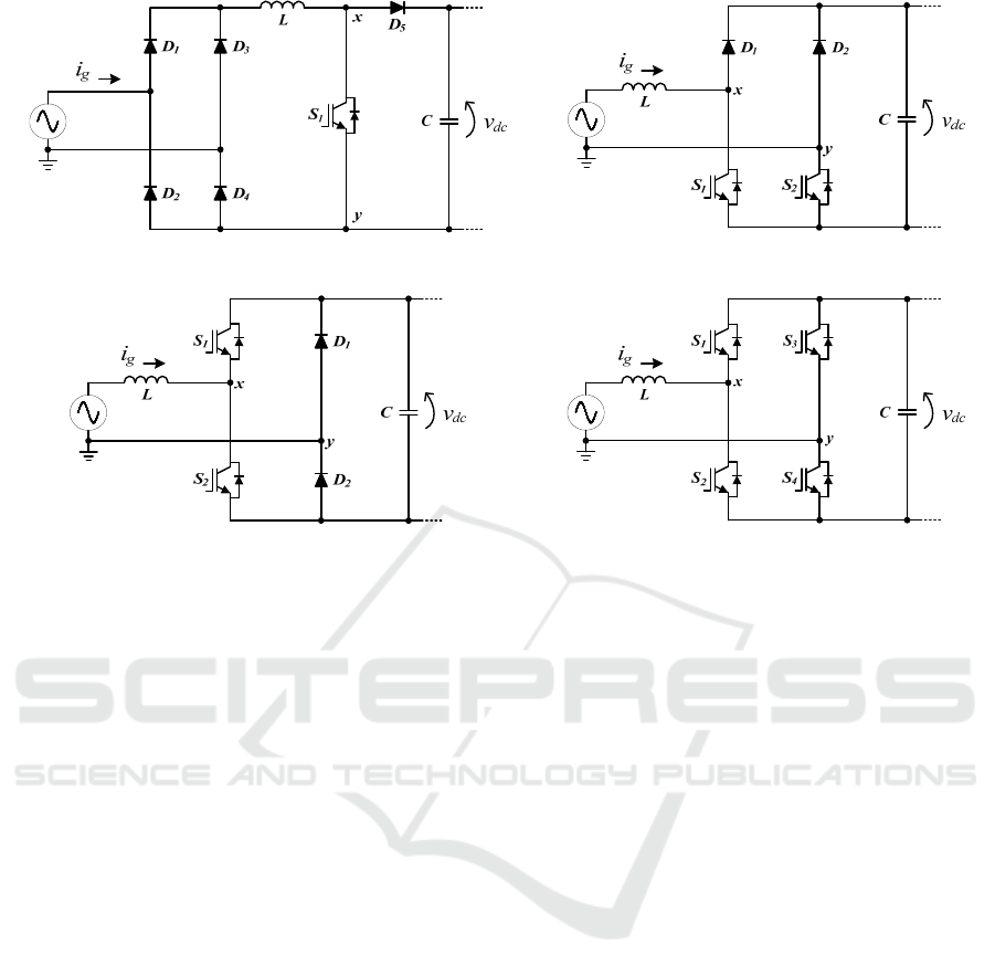
Figure 1: Single-phase active rectifiers under comparison: (a) Traditional power-factor-correction (PFC); (b) Symmetrical
bridgeless; (c) Asymmetrical bridgeless; (d) Full-bridge full-controlled.
active rectifiers is presented in (Wei, 1998), and a
comprehensive review of control strategies for
active rectifiers considering the main advantages and
disadvantages is presented in (Yang, 1998). Active
rectifiers are used in EV chargers in order to obtain a
sinusoidal grid current in phase with the power grid
voltage. However, comparing with the traditional
solutions based in the ac-dc diode bridge rectifier,
the power hardware is much more complex and
requires a digital control platform, increasing the
costs and the power density of the implementation.
The impact of the EV introduction in residential
electrical installations in terms of power quality is
presented in (Lambert, 2002). Detailed studies about
this subject are presented in (Morcos, 2002), where,
for instance, is shown that the GM EV1 presents a
total harmonic distortion (THD) that varies from 3%
to 28.11% and a power factor from 1 to 0.96
according to the battery state-of-charge.
In this context, the main contribution of this
paper is an experimental comparison of single-phase
active rectifiers for EV battery chargers. Section II
presents the power hardware structure of the active
rectifiers under comparison, including a comparison
in terms of required components. Section III
presents a detailed description of the control
algorithms. Section IV presents an experimental
validation of all the active rectifiers under
comparison. Finally, section V presents the main
conclusions that can be retrieved from the presented
comparison.
2 HARDWARE STRUCTURE OF
THE ACTIVE RECTIFIERS
UNDER COMPARISON
This section describes the hardware structure of the
active rectifiers under comparison. A reconfigurable
3.6 kW on-board EV battery charger was used to
obtain the different structures. Such EV charger is
composed by a front-end ac-dc converter and by a
back-end dc-dc converter with a shared dc-link
capacitor. Figure 1 shows the four single-phase
active rectifiers under comparison.
The traditional power-factor-correction (PFC)
active rectifier (cf. Figure 1(a)) is composed by
full-bridge diode rectifier followed by a boost dc-dc
converter. As shown, this active rectifier requires
five diodes and a single totally controlled
semiconductor, in this case an insulated-gate bipolar
transistor (IGBT) is used. The circuit to control the
IGBT can be directly connect to the control circuit,
i.e., it is not necessary isolation between the power
circuit and the control circuit. This can be an
important advantage of this active rectifier
comparing with the others. The symmetrical
bridgeless active rectifier (cf. Figure 1(b)) is
(b)(a)
(c) (d)
SMS 2017 - Special Session on Sustainable mobility solutions: vehicle and traffic simulation, on-road trials and EV charging
420
composed by two legs, each one formed by a diode
and by an IGBT. Similarly to the previous active
rectifier, the circuit to control the IGBTs can be
directly connect to the control circuit, i.e., it is not
necessary isolation between the power circuit and
the control circuit, once the emitter of both IGBTs is
connected to the same point. On the other hand, the
asymmetrical bridgeless active rectifier (cf. Figure 1
(c)) is composed by a leg formed by two diodes and
by a leg formed by two IGBTs. In this active
rectifier is necessary isolation between the drivers
circuit of both IGBTs, representing a disadvantage
of this active rectifier comparing with the previous.
Finally, the full-bridge full-controlled active rectifier
(cf. Figure 1 (d)) is composed by two legs, each one
formed by two IGBTs. In this active rectifier is also
necessary to establish isolation between the drivers
of the IGBTs, i.e., only the drivers of the IGBTs S
2
an S
4
can be referred to the same point.
3 CONTROL ALGORITHMS OF
THE ACTIVE RECTIFIERS
UNDER COMPARISON
This section presents a detailed explanation about
the control algorithms of the active rectifiers under
comparison.
3.1 Traditional Power Factor
Correction (PFC)
Concerning power quality, the main requirements of
the EV battery chargers are sinusoidal grid current
and unitary power factor. The most used active
rectifier to accomplish with such requirements is the
traditional PFC, i.e., a full-bridge diode rectifier
followed by a dc-dc boost converter operating with
controlled input current and controlled output
voltage. It is important to note that there are some
PFC converters that are used only to operate with
controlled power factor, as example, the flyback
topology proposed in (Ma, 2010) and the full-bridge
topology proposed in (Moschopoulos, 2003). An
extended review about PFC converters based in the
boost converter is presented in (García, 2003), and a
concrete case of a PFC boost-type for EV chargers is
proposed in (Lee, 2011). The PFC active rectifier
operates in unidirectional mode and is classified as a
two-level converter, i.e., the voltage between the
points x and y, identified in Figure 1 (a) can assume
the levels 0 and +v
dc
. When the IGBT is off, the
voltage v
xy
(collector-emitter voltage in the IGBT) is
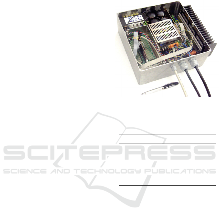
Figure 2: Reconfigurable laboratorial prototype of the
on-board EV battery charger used to obtain the
experimental results.
Table 1: Main characteristics of the developed laboratorial
prototype used for experimental validation.
Characteristic Value Unit
Switching frequency 20 kHz
Sampling frequency 40 kHz
Power grid voltage 50 V
Power Grid Voltage THD% 3% -
Power grid frequency 50 Hz
Output voltage 100 V
+v
dc
, and when the IGBT is on, the voltage v
xy
is 0.
Therefore, the maximum voltage applied to the
IGBT is +v
dc
. The output voltage of the full-bridge
diode rectifier is the power grid voltage rectified
and, due to the input inductance and the control
algorithm, the grid current is sinusoidal and in phase
with the power grid voltage.
3.2 Symmetrical and Asymmetrical
Bridgeless
In the previous item, section 3.1, it was introduced
the traditional PFC composed by a full-bridge diode
rectifier followed by a dc-dc boost converter, i.e., an
active rectifier that requires two power stages.
However, these stages can be rearranged in order to
form an active rectifier without the full-bridge diode
rectifier. Such topologies are identified in the
literature as bridgeless or dual-boost. A review about
active rectifiers with single stage is presented in
Experimental Comparison of Single-Phase Active Rectifiers for EV Battery Chargers
421

(Huber, 2008). The main bridgeless active rectifiers
identified in the literature are the symmetrical and
asymmetrical (Martinez, 1996), (Lim, 1999).
Comparing with the traditional PFC, bridgeless
active rectifiers requires one more IGBT, but less
three diodes. However, it should be noted that the
hardware project of such topologies is more complex
once is required the double of the IGBTs drivers. On
the other hand, comparing both bridgeless structures,
the symmetrical bridgeless has as main advantage
comparing with the asymmetrical the simplicity of
the IGBTs drivers as well as the Impossibility of
short circuits in the same leg when both IGBTs are
on. A comparison between the symmetrical and the
asymmetrical bridgeless active rectifiers,
highlighting the benefits of the symmetrical is
presented in (Choi, 2007). Comparing with the
traditional PFC, the switching losses are very similar
once each IGBT is switched during each half-cycle
of the power grid voltage (positive and negative) and
the IGBT of the traditional PFC is switched in both
half-cycles. Similarly to the traditional PFC,
symmetrical and the asymmetrical bridgeless active
rectifiers operate in unidirectional mode, but can be
controlled to produce three distinct voltage levels,
i.e., the voltage v
xy
can assume the values +v
dc
, 0 and
–v
dc
. For the symmetrical bridgeless active rectifier,
during the positive half-cycle of the power grid
voltage, when the IGBT S
1
is on and the IGBT S
2
is
off, the voltage v
xy
is 0, and when both IGBTs are
off the voltage v
xy
is +v
dc
. On the other hand, during
the negative half-cycle of the power grid voltage,
when the IGBT S
1
is off and the IGBT S
2
is on, the
voltage v
xy
is 0, and when both IGBTs are off the
voltage v
xy
is -v
dc
. For the asymmetrical bridgeless
active rectifier the reasoning is the same, only
changing the position of the IGBTs. For both
converters, the maximum voltage applied to each
IGBT is +v
dc
.
3.3 Full-Bridge Full-Controlled
The full-bridge active rectifier is composed by two
legs of IGBTs. This active rectifier can produce
three distinct voltage levels, i.e., the voltage v
xy
can
assume the values of –v
dc
, 0 and +v
dc
. During the
positive half-cycle of the power grid voltage, when
the IGBTs S
1
and S
3
are off and the IGBTs S
2
and S
4
are on, the voltage v
xy
is 0 (changing the state of all
the IGBTs the voltage v
xy
is also 0), and when the
IGBTs S
2
and S
3
are off and the IGBTs S
1
and S
4
are
on, the voltage v
xy
is +v
dc
. During the negative
half-cycle of the power grid voltage, when the
IGBTs S
1
and S
3
are off and the IGBTs S
2
and S
4
are
on, the voltage v
xy
is 0 (changing the state of all the
IGBTs the voltage v
xy
is also 0), and when the
IGBTs S
2
and S
3
are on and the IGBTs S
1
and S
4
are
off, the voltage v
xy
is –v
dc
. The maximum voltage
applied to each IGBT is v
dc
. The main advantage of
this active rectifier comparing with the previous is
the possibility to operate in bidirectional mode, i.e.,
the EV charger can be used to transfer energy from
the batteries to the power grid. This is an important
characteristic considering the future scenarios of
smart grids.
4 EXPERIMENTAL VALIDATION
This section presents the experimental validation
considering the active rectifiers described in the
previous items. The reconfigurable laboratorial
prototype of the on-board EV battery charger used to
obtain the experimental results is shown in Figure
,
and the main characteristics of the experimental
validation are presented in table I. The experimental
results were obtained in laboratorial environment
with a Tektronix TPS 2024 digital oscilloscope.
For the traditional PFC active rectifier, Figure
shows the power grid voltage (v
g
), the dc-link
voltage (v
dc
), and the grid current (i
g
) during a time
interval of 50 ms. As expected, the grid current (i
g
)
is sinusoidal and in phase with the power grid
voltage (v
g
), and the dc-link voltage (v
dc
) is
controlled. As it can be seen, the grid current (i
g
) has
lower THD% than the power grid voltage (v
g
) due to
the control algorithm, i.e., instead of use the real
instantaneous values of power grid voltage a
phase-locked loop (PLL) algorithm is used. Figure
shows the harmonic spectrum of the grid current and
a measured THD% of 3.25%.
For the symmetrical bridgeless active rectifier,
Figure 5 shows the power grid voltage (v
g
), the
dc-link voltage (v
dc
), and the grid current (ig) during
a time interval of 50 ms. As for the previous active
rectifier, the grid current (i
g
) is sinusoidal and in
phase with the power grid voltage (v
g
), and the
dc-link voltage (v
dc
) is controlled. In this case, the
grid current (i
g
) has also lower THD% than the
power grid voltage (v
g
) due to the PLL algorithm.
Nevertheless, in this case grid current (i
g
) has a
THD% greater than with the traditional PFC active
rectifier. Figure 6 shows the harmonic spectrum of
the grid current and a measured THD% of 5.88%.
For the asymmetrical bridgeless active rectifier,
Figure 7 shows the power grid voltage (v
g
), the
dc-link voltage (v
dc
), and the grid current (i
g
) during
SMS 2017 - Special Session on Sustainable mobility solutions: vehicle and traffic simulation, on-road trials and EV charging
422
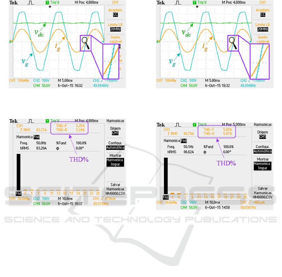
Figure 3: Experimental results of the traditional power
factor correction topology: Power grid voltage (v
g
);
Dc-link voltage (v
dc
); Grid current (i
g
).
Figure 4: Experimental results of the traditional power
factor correction topology: Harmonic spectrum of the grid
current and measured THD%.
a time interval of 50 ms. Similarly to the previous
case, the grid current (i
g
) is sinusoidal and in phase
with the power grid voltage (v
g
), the dc-link voltage
(v
dc
) is controlled, and the grid current (i
g
) has lower
THD% than the power grid voltage (v
g
) due to the
PLL algorithm. Comparing with the symmetrical
bridgeless active rectifier, this active rectifier
presents a grid current (i
g
) with higher THD%.
Figure 8 shows the harmonic spectrum of the grid
current and a measured THD% of 5.98%. Finally,
for the full-bridge active rectifier, Figure 9 shows
the power grid voltage (v
g
), the dc-link voltage (v
dc
),
and the grid current (ig) during a time interval of
50 ms. In the same way as the previous cases, the
grid current (i
g
) is sinusoidal and in phase with the
power grid voltage (v
g
), the dc-link voltage (v
dc
) is
controlled, and the grid current (i
g
) has lower THD%
than the power grid voltage (v
g
) due to the PLL
algorithm. The grid current (i
g
) of this active rectifier
presents the lower THD% considering all the active
Figure 5: Experimental results of the symmetrical
bridgeless topology: Power grid voltage (vg); Dc-link
voltage (vdc); Grid current (ig).
Figure 6: Experimental results of the symmetrical
bridgeless topology: Harmonic spectrum of the grid
current and measured THD%.
rectifiers under comparison. Figure 10 shows the
harmonic spectrum of the grid current and a
measured THD% of 2.13%.
5 CONCLUSIONS
An experimental comparison of single-phase active
rectifiers for EV battery chargers was presented.
Four topologies of active rectifiers were considered
for comparison: traditional power factor correction
(PFC); symmetrical bridgeless; asymmetrical
bridgeless; and full-bridge full-controlled.
Considering the hardware structure, the PFC
requires less IGBTs, but more diodes, and the
full-bridge full-controlled requires more IGBTs but
no one diode. Moreover, the full-bridge
full-controlled allows the operation mode in
bidirectional mode, which can be an important
feature for EV battery chargers in a smart grid
Experimental Comparison of Single-Phase Active Rectifiers for EV Battery Chargers
423
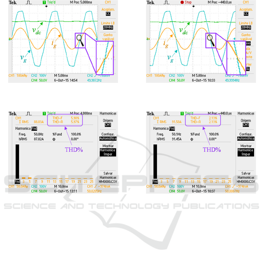
Figure 7: Experimental results of the asymmetrical
bridgeless topology: Power grid voltage (vg); Dc-link
voltage (vdc); Grid current (ig).
Figure 8: Experimental results of the asymmetrical
bridgeless topology: Harmonic spectrum of the grid
current and measured THD%.
scenario. Analysing the power quality issues in
terms of the grid current THD%, the full-bridge
full-controlled is the best, presenting the lower value
(2.13%), and the bridgeless asymmetrical is the
worst, presenting the higher value (5.98%). Along
the paper the comparison between the active
rectifiers is presented through experimental results
using a reconfigurable developed laboratorial
prototype of an on-board EV battery charger.
ACKNOWLEDGEMENTS
This work has been supported by COMPETE:
POCI-01-0145-FEDER-007043 and FCT –
Fundação para a Ciência e Tecnologia within the
Project Scope: UID/CEC/00319/2013. This work is
financed by the ERDF – European Regional
Development Fund through the Operational
Programme for Competitiveness and
Internationalisation ‐ COMPETE 2020 Programme,
Figure 9: Experimental results of the full-bridge full-
controlled topology: Power grid voltage (vg); Dc-link
voltage (vdc); Grid current (ig).
Figure 10: Experimental results of the full-bridge full-
controlled topology: Harmonic spectrum of the grid
current and measured THD%.
and by National Funds through the Portuguese
funding agency, FCT ‐ Fundação para a Ciência e a
Tecnologia, within project SAICTPAC/0004/2015‐
POCI‐ 01‐0145‐FEDER‐016434.
REFERENCES
Clement, K., Haesen, E., Driesen, J., (2010). The Impact
of Charging Plug-In Hybrid Electric Vehicles on a
Residential Distribution Grid. IEEE Trans. on Power
Systems.
Clement, K., Haesen, E., Driesen, J., (2009). Coordinated
charging of multiple plug-in hybrid electric vehicles in
residential distribution grids. PSCE Power Systems
Conference and Exposition.
Choi, W. Y., Kwon, J. M., Kim, E. H., Lee, J. J., Kwon, B.
H., (2007). Bridgeless Boost RectifierWith Low
Conduction Losses and Reduced Diode Reverse-
Recovery Problems. IEEE Trans. on Industrial
Electronics.
SMS 2017 - Special Session on Sustainable mobility solutions: vehicle and traffic simulation, on-road trials and EV charging
424

Escudero-Garzás, J. J., García-Armada, A., Seco-
Granados, G., (2012). Fair Design of Plug-in Electric
Vehicles Aggregator for V2G Regulation. IEEE
Trans. on Vehicular Technologies.
Ferreira, J. C., Monteiro, V., Afonso, J. L., (2014).
Vehicle-to-Anything Application (V2Anything App)
for Electric Vehicles. IEEE Trans. on Industrial
Informatics.
Ferreira, J. C., Monteiro, V., Afonso, J. L., (2013).
Dynamic range prediction for an electric vehicle.
EVS27 Electric Vehicle Symposium and Exhibition.
Ferreira, J. C., Silva, A. R., Monteiro, V., Afonso, J. L.,
(2013). Collaborative Broker for Distributed Energy
Resources. Conference on Computational Intelligence
and Decision Making.
Freire, R., Delgado, J., Santos, J. M., Almeida, A. T.,
(2010). Integration of Renewable Energy Generation
with EV Charging Strategies to Optimize Grid Load
Balancing. IEEE Conference on Intelligent
Transportation Systems.
Gautam, D. s., Musavi, F., Edington, M., Eberle, W.,
Dunford, W. g., (2012). An Automotive Onboard 3.3-
kW Battery Charger for PHEV Application. IEEE
Trans. on Vehicular Technologies.
García, O., Cobos, J. A., Prieto, R., Alou, P., Uceda, J.,
(2003). Single Phase Power Factor Correction: A
Survey. IEEE Trans. on Power Electronics.
Huber, L., Jang, Y., Jovanovic, M., (2008). Performance
Evaluation of Bridgeless PFC Boost Rectifier. IEEE
Trans. on Power Electronics.
Inoa, E., Wang, J., (2011). PHEV Charging Strategies for
Maximized Energy Saving. IEEE Trans. on Vehicular
Technologies.
Khaligh, A., Li, Z.,(2010). Battery, Ultracapacitor, Fuel
Cell, and Hybrid Energy Storage Systems for Electric,
Hybrid Electric, Fuel Cell, and Plug-In Hybrid Electric
Vehicles: State of the Art. IEEE Trans. on Vehicular
Technologies.
Kramer, B., Chakraborty, S., Kroposki, B., (2008). A
review of plug-in vehicles and vehicle-to-grid
capability. IEEE IECON Industrial Electronics
Conference.
Lee, C. S., Jeong, J. B., Lee, B. H., Hur, J., (2011). Study
on 1.5 kW Battery Chargers for Neighborhood Electric
Vehicles. IEEE VPPC Vehicle Power and Propulsion
Conference.
Lambert, F., (2002). Secondary Distribution Impacts of
Residential Electric Vehicle Charging. California
Energy Commission.
Lopes, J. A. P., Soares, F., Almeida, P. M. R., (2011).
Integration of Electric Vehicles in the Electric Power
Systems. Proceedings of the IEEE.
Lim, J. W., Kwon, B. H., (1999). A Power-Factor
Controller for Single-Phase PWM Rectifiers. IEEE
Trans. on Industrial Electronics.
Moschopoulos, G., (2003). A Simple AC–DC PWM Full-
Bridge Converter With Integrated Power-Factor
Correction. IEEE Trans. on Power Electronics.
Ma, H., Ji, Y., Xu, Y., (2010). Design and Analysis of
Single-Stage Power Factor Correction Converter With
a Feedback Winding. IEEE Trans. on Power
Electronics.
Milberg, J., Ann Schlenker, A., (2011). Plug into the
Future. IEEE Power and Energy Magazine.
Martinez, R., Enjeti, P. N., (1996). A High-Performance
Single-phase Rectifier with Input Power Factor
Correction. IEEE Trans. on Power Electronics.
Morcos, M., Dillman, N., Mersman, C., (2002). Battery
Chargers for Electric Vehicles. IEEE Power
Engineering Review.
Monteiro, V., Gonçalves, H., Afonso, J. L., (2011). Impact
of Electric Vehicles on Power Quality in a Smart Grid
Context. IEEE EPQU International Conference on
Electrical Power Quality and Utilisation.
Monteiro, V., Exposto, B., Pinto, J. G., Almeida, R.,
Ferreira, J. C., Meléndez, A. A. N., Afonso, J. L.,
(2014). On-Board Electric Vehicle Battery Charger
with Enhanced V2H Operation Mode. IEEE IECON
Industrial Electronics Conference.
Monteiro, V., Ferreira, J. C., Pinto, J. G., Pedrosa, D.,
Afonso, J. L., (2010). iV2G Charging Platform. IEEE
ITSC International Conference on Intelligent
Transportation Systems.
Monteiro, V., Ferreira, J. C., Meléndez, A. A. N., Afonso,
J. L., (2016). Model predictive control applied to an
improved five-level bidirectional converter. IEEE
Transactions on Industrial Electronics.
Monteiro, V., Exposto, B., Ferreira, J. C., Afonso, J. L.,
(2016). Improved vehicle-to-home (iV2H) operation
mode: experimental analysis of the electric vehicle as
off-line UPS. IEEE Trans. on Smart Grid.
Rajashekara, K., (2013). Present Status and Future Trends
in Electric Vehicle Propulsion Technologies. IEEE
Journal of Emerging and Selected Topics in Power
Electronics.
Rei, R. J., Soares, F. J., Almeida, P. M. R., Lopes, J. A. P.,
(2010). Grid Interactive Charging Control for Plug-in
Electric Vehicles. IEEE Conference on Intelligent
Transportation Systems.
Raghavan, S. S., Khaligh, A., (2012). Electrification
Potential Factor: Energy-Based Value Proposition
Analysis of Plug-In Hybrid Electric Vehicles. IEEE
Trans. on Vehicular Technologies.
Wirasingha, S. G., Emdai, A., (2011). Classification and
Review of Control Strategies for Plug-In Hybrid
Electric Vehicles. IEEE Trans. on Vehicular
Technologies.
Wei, H., Batarseh, I., (1998). Comparison of basic
converter topologies for power factor correction. IEEE
Southeastcon Proceedings.
Yang, Z., Sen, P. C., (1998). Recent developments in high
power factor switchmode converters. IEEE Canadian
Conference on Electrical and Computer Engineering.
Experimental Comparison of Single-Phase Active Rectifiers for EV Battery Chargers
425
