
Tool Support to Automate Transformations between CIM and PIM
Levels
Imane Essebaa and Salima Chantit
Computer Laboratory of Mohammedia (LIM), Faculty of Sciences and Technics Mohammedia,
Hassan II university of Casablanca, Mohammedia, Morocco
Keywords:
CIM, PIM, Model Transformations, SBVR, UML Diagrams, Eclipse Plug-in.
Abstract:
The Model Driven Architecture is a specific variant of Model Driven Engineering that aims to separate differ-
ent areas of concerns. This architecture is defined by three levels of abstraction, i.e. Computation Independent
Model (CIM), Platform Independent Model (PIM) and Platform Specific Model (PSM) that defines the archi-
tecture of the generated code. The transition between these levels is realized throw Model Transformations
which are the core of MDA. In this paper we will focus on the highest level of abstraction of MDA which is
represented by Computation Independent Model and its transformation into the Platform Independent Model.
Our approach is based primarily on OMG standards: UML diagrams (Unified Modeling Languages) and
SBVR (Semantic Business Vocabulary and Business Rules). We represent the CIM level by an extension of
Use Case Diagram to support Data Object elements, and SBVR standard, while after transformation the PIM
level is modeled by Business Class Diagram and System Sequence Diagrams. The paper presents also the im-
plementation of our approach which is an eclipse plug-in that allows to automatically transform models from
CIM to PIM. We furthermore illustrate our approach with a case study of a car rental agency management
application.
1 INTRODUCTION
To stay competitive, companies seek more and more
to increase their productivity and their effectiveness.
They are in permanent quest of reliable tools that will
cover the most features. In this context, the OMG pro-
posed their initiative called MDA (Model Drive Ar-
chitecture), which has for objective the elaboration of
sustainable models that are independent from techni-
cal details and executions platforms (JEE, PHP, .net),
in order to develop more rapidly software system and
generate automatically source code in the chosen plat-
form . The MDA approach is a specific variant of
Model Driven Engineering (MDE) which is an alter-
native approach of system information development.
The concept behind this approach is to create source
models in the highest level of abstraction and trans-
form them to multiple levels until generating automat-
ically source code. It aims to automate the process
of software development which is done manually by
specialists. The MDA is the most important variant of
MDE, indeed it describes the architecture that ensures
the main objective of MDE which is the separation of
system requirements from their implementation in a
specific platform.
The MDA approach is defined by several models
and meta-models, that serve as the first step to model
the application, and then to generate source code by
successive model transformations. These models are
classified into three levels of abstraction to reach the
main objective of MDA which is the separation of
concerns(Soley, 2000):
• CIM (Computation Independent Model): This
level is used by Business Manager and Business
Analysts that model the system requirements and
describe the business activities to meet the busi-
ness objectives.
• PIM (Platform Independent Model): This level
describes the Business Logic of the system re-
gardless of technical platform.
• PSM (Platform Specific Model): that adds to PIM
the technological aspects of the target platform. It
is called also the model of code.
The transition from one level to the next is real-
ized through successive transformation rules. In this
context, we limited our focus to the highest levels of
abstraction: CIM and PIM levels. This paper presents
Essebaa, I. and Chantit, S.
Tool Support to Automate Transformations between CIM and PIM Levels.
DOI: 10.5220/0006388703670378
In Proceedings of the 12th International Conference on Evaluation of Novel Approaches to Software Engineering (ENASE 2017), pages 367-378
ISBN: 978-989-758-250-9
Copyright © 2017 by SCITEPRESS – Science and Technology Publications, Lda. All rights reserved
367

our approach on how to model each level and defines
transformation rules that allow the automatic gener-
ation of the PIM from the CIM. We also describe
an eclipse plug-in conception that implement our ap-
proach.
This paper is organised as follow: In the second
section we describe the context of our research. Sec-
tion 3 presents the previous works made on this con-
text, while section 4 presents our approach to trans-
form the CIM to the PIM level. Then the following
section (section 5) describes tools used to implement
our approach. In section 6, we apply the approach
on a case study to illustrate results of our transforma-
tions, and we finish by a conclusion and some future
works.
2 OVERVIEW OF CONCEPTS
2.1 Model Driven Architecture
Model Driven Architecture (MDA) was published by
the OMG (Object Management Group) in 2000. This
standard is intended to provide a new way to de-
sign applications by separating the business logic of
the company from any technical platform. Indeed,
the business logic and technologies are in current
changes. It is, therefore, obvious to separate the two
to deal with the growing complexity of information
systems and strong technological migration costs.
This separation allows the capitalization of soft-
ware knowledge and the know-how of the company.
At this level, the object and the component ap-
proaches did not keep their promises. It was becom-
ing increasingly difficult to develop software based on
these technologies. The use of additional processes,
such as design patterns or aspect oriented program-
ming, was necessary.
The standard MDA offers also the possibility to
stop the stack of technologies that requires keeping
special skills to bring together various systems. This
is enabled through the passage from an interpreta-
tive approach to a transformational approach. In the
interpretative approach, human has an active role in
the construction of information systems while in the
transformational approach, it has a simplified and
reduced role thanks to the automated construction.
(Miller and Mukerji, 2003)
2.2 Model Transformations
The transition from one level to another is realized by
applying transformations to source elements, to gen-
erate target elements.
Model Transformation is the key of MDA ap-
proach, it aims to generate automatically the source
code of the application from successive automatic
transformations; CIM to PIM, PIM to PSM, then PSM
to source code. Each transformation adds necessary
information to generate source code, and ensures the
traceability link between MDA models that guarantee
the quality of software.
There are two types of model transformations;
model to model transformation which is from CIM
to PIM, and from PIM to PSM, the second type is
model to text which is the generation of source code
from PSM (PSM to Code). In this work we will focus
on model to model transformation, specially between
CIM and PIM.
The next section, we present different works and
approaches proposed on this context.
3 RELATED WORKS
Model Transformations are considered as the main re-
search area of the MDA approach Several works were
realized in this context. However, most of them fo-
cused on the generation of the source code from PSM
level which is the result of transformations from PIM
level. In our research, we focused on transformations
from CIM to PIM level on which few studies has been
conducted. In this section we present our analysis of
previous works in this context which is based on the
different aspects defined by OMG for CIM and PIM
levels and the logic between models.
N.Addamssiri and al. modeled in their approach
(N.Addamssiri et al., 2014) CIM level by Business
Process Modeling and Notation (BPMN) and then
through horizontal transformations Use Case Dia-
gram and SBVR are generated. The PIM level in
this approach is represented by System Sequence Di-
agram which is the result of vertical transformations
from CIM. We note that this approach covers all CIM
aspects (Functional, Behavioral and static) while the
structural aspect of PIM level was not covered as the
System Sequence Diagram covers just PIM behav-
ioral aspect. We also note that the CIM level was
very detailed as recommended by OMG, while PIM
level contains less details about the system. Indeed
the BPMN diagram is more detailed than System Se-
quence Diagram.
In their paper (Kherraf et al., 2008), Kherraf and
al. propose to model the CIM level by the UML Ac-
tivity Diagram, which is detailed by requirements and
transformed to System Components Diagram in PIM
level. We note that this approach does not cover all
aspects of both CIM and PIM levels. Indeed the Ac-
MDI4SE 2017 - Special Session on Model-Driven Innovations for Software Engineering
368

tivity diagram covers only the behavioural aspect of
CIM, while the Component Diagram covers the struc-
tural aspect of PIM.
Kriouile and al. (A.Kriouile, 2015) modelled the
CIM level by two diagrams: Business Process Model
Diagram and Use Case Diagram, while the PIM level
is represented by Domain Class Diagram and Se-
quence Diagram which are generated using transfor-
mation rules between CIM and PIM levels. It is true
that this method covers all the MDA aspects but we
note that the defined rules to generate PIM level from
CIM are not complete. For example there is no as-
sociations between classes. We have to note also that
CIM level is more detailed than PIM level by the use
of BPM Diagram in CIM level.
In their method (Kardo and Drozdov, 2010),
Kardo and al. modelled the CIM level using Data
Flow Diagram (DFD) while the PIM level was mod-
elled using four UML diagrams: Use Case Diagram,
Activity Diagram, Sequence Diagram and the domain
models. This method does not cover all aspects of the
CIM level as the behavioural aspect was neglected.
Wu and al. Method (Wu et al., 2007) describes
how to get PIM level from CIM one, and the trans-
formation of PIM into PSM. In this method CIM is
represented by Use Case Diagram, Activity Diagram
and robustness diagram, while the PIM one was rep-
resented by Sequence Diagram and Class diagram.
Even if this method covers all aspects of MDA lev-
els, the defined rules are not complete as they do not
allow to generate all diagrams elements in PIM level.
In our first work we chose to model the CIM level
by Use Case Diagram and Activity Diagram, and
through transformation rules we generate PIM level
which is represented by Business Class Diagram and
System Sequence Diagram. While testing this ap-
proach, we deduce that we can not generate all di-
agrams elements in PIM level such as associations
and their cardinality. To resolve this problem, in our
second work, we used the OMG standard SBVR to
express relations between elements, which is trans-
formed into OCL constraints. Thus CIM level was
represented by the Use Case Diagram, Activity Dia-
gram, SBVR standard and OCL constraints and the
mapping in this approach was realized through QVT
rules which mean that transformations were not au-
tomated. We note that the use of Activity Diagram
in CIM level gives more details in this level as rec-
ommended by the OMG. In the current paper we will
present an amelioration of previous methods to auto-
mate transformations and to optimize the use of mul-
tiple diagrams.(Essebaa and Chantit, 2017) (Essebaa
and Chantit, 2016)
In their paper, Bouseta and al.(B. BOUSETTA,
2013) describes a method to construct CIM level and
transform it (semi-) automatically to PIM level. In
this approach, CIM level is modeled by BPMN dia-
gram to cover both static and behavioral aspects, and
Usecase diagram to cover functional aspect. These
diagrams are used to generate the PIM level which
is represented by Domain Class Diagram (DCD) that
define the structural aspect and System Sequence Di-
agram that cover the Dynamic aspect. This approach
covers all CIM and PIM levels aspects previously
cited but does not allow the automatic generation of
PIM level from CIM. We also note that using BPMN
in CIM level gives more detailed information of the
system than System Sequence Diagram used in PIM
level, that do not meet the standards of abstraction re-
quired by the OMG. In addition, using BPMN and
Usecase diagram in the same level leads to a redun-
dancy of information.
Furthermore, there exist several studies where au-
thors propose just to model CIM level without defin-
ing transformation rules to get PIM level.(Sharifi and
Mohsenzadeh, 2012)
The analysis that we did on previous works al-
lows us to deduce that transformation rules proposed
are not completely defined and not automatic. Based
on this analysis, we conclude that previous methods
may be classified into two categories: researchers
that did not cover all the various aspects of CIM and
PIM levels (Kardo and Drozdov, 2010),(Kherraf et al.,
2008) and researchers that cover the different aspects
of CIM and PIM but did not define complete transfor-
mation rules(B. BOUSETTA, 2013),(Wu et al., 2007),
(A.Kriouile, 2015),(N.Addamssiri et al., 2014).
In the second part of this section, we will present
previous works made on the context of transformation
of SBVR to UML.
In their paper (Afreen et al., 2011), H. Afreen
and al. proposed an approach to extract manually the
Object-Oriented information from SBVR then to gen-
erate Class model. The paper proposes a conception
of an eclipse plug-in called SBVR2UML that may
generate Class model but it does not contain any de-
scription on how the link is made between these ele-
ments. We also note that this approach does not auto-
mate transformation between SBVR and UML Class
Model, indeed the Oriented-Object information are
generated manually. Moreover the paper defines just a
conception of an eclipse plug-in called SBVR2UML.
We note also that this approach does not define how
to generate other diagrams such as Sequence Diagram
or Activity Diagram.
A.Raj and al. present in their paper (Raj et al.,
2008) an approach to transform SBVR into several
UML diagrams: Class Diagram and Activity Dia-
Tool Support to Automate Transformations between CIM and PIM Levels
369

gram. We note that this approach describes for each
generation the algorithm to follow in order to get
UML Diagrams, but this generation is still limited as
it does not for example define how to get parameters
of Class operation. Furthermore, in order to gener-
ate Activity Diagram, the approach takes in account
just if then conditions but does not explain how it will
be transformed and how the diagram is generated. In
this paper, authors consider the SBVR standard in the
CIM level of MDA, while generated UML diagrams
(Class Diagram, Activity Diagram and Sequence Di-
agram) represent the PIM level. We also note that the
Activity Diagram contains the same information as
the Sequence Diagram modeled differently and their
use in the same level does not add more information.
It exists another type of approaches that focuses
on modeling CIM level and its transformation to PIM
level, these approaches are basically based on Topo-
logical Functionning Modeling ”is a model developed
by Janis Osis at Riga Technical University (RTU,
former Riga Polytechnic Institute) in 1969” (J.Osis,
1969), these approaches have a Mathematical back-
ground which proved the formalism aspect used in
higher level of abstraction of the MDA (Solomencevs,
2016) (Ovchinnikova and Nazaruka, 2016).
4 PROPOSED APPROACH
In this section we present our proposed approach to
automate transformations between CIM and PIM lev-
els, our approach consists on:
• Modeling system’s requirements by an extended
use case diagram in CIM level.
• Describing Business Vocabulary and Business
Rules of the system using SBVR standard in CIM
level
• Applying transformation rules implemented in an
eclipse plug-in to generate automatically Business
Class Diagram and System Sequence Diagrams
that represent PIM level.
Figure 1 below describes this approach:
4.1 CIM Level in Our Approach
The CIM level is the most abstract level in MDA ap-
proach. This level is considered as the most important
because it models system requirements, and from this
model we can generate all the other levels of MDA;
other models are affected if any changes is made in
CIM level.
To well represent and cover all the system require-
ments in CIM level the OMG recommends, the CIM
Figure 1: Overview of our proposed approach.
level should cover three aspects as defined by Kriouile
and al in their paper (A.Kriuouile, 2013); Functional,
Behavioral and Static, but does not present any con-
sensus or recommendation about how the CIM level
should be represented or even how many models or
which of them we have to use.
In order to respect OMG recommendations and to
cover all the aspect of CIM level, we propose to rep-
resent it by an extended Use Case Diagram and OMG
standard SBVR.
In this paper we present an improved version of
our previous proposed approaches, that express con-
straints using only Business Rules of SBVR standard,
We minimize horizontal transformations in CIM level
to get OCL constraints from SBVR we eliminate the
Activity Diagram and propose to define the behavioral
aspect of the system using Business rules, we opti-
mized our approach in order to respect the abstrac-
tion required for the CIM level and also make our tool
more simple to use.
4.1.1 UML use case Diagram
OMG (Object Management Group) defines a Use
Case as: the specification of a set of actions per-
formed by a system, which yields an observable re-
sult that is, typically, of value for one or more actors
or other stakeholders of the system”. (OMG, 2011)
The choice of using UML Use Case Diagram is
due to its simplicity to express system requirements
and the link between actors in the system and func-
tionalities, Use Case Diagram is such a bridge that
covers the gap between the simple user of the system
and the software designer, indeed it gives a general
view of the system.
A simplified version of the metamodel of the Busi-
ness Use Case Diagram is represented in the figure 2:
MDI4SE 2017 - Special Session on Model-Driven Innovations for Software Engineering
370
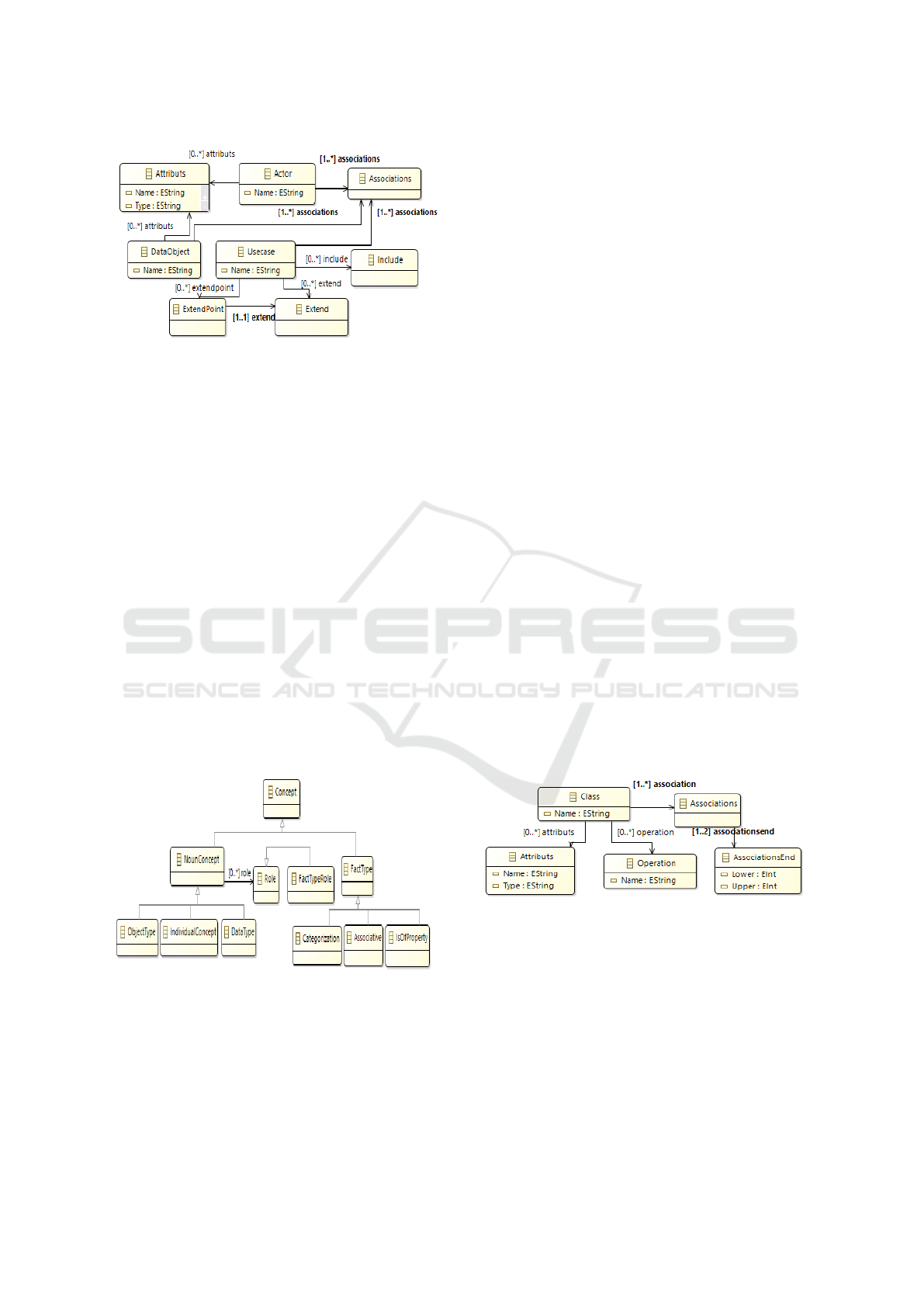
Figure 2: Main fragments of Use Case Diagram Meta-
model.
4.1.2 Semantic Business Vocabulary and
Business Rules
The OMG standard Business Vocabulary and Busi-
ness Rules (SBVR), is a specification that was ac-
cepted by the OMG in 2005. The basic idea behind
SBVR is to express the requirements in a structured
language. It allows the business analyst or a business
person to express system requirements using struc-
tured English instead of using its own language.(SBV,
2008) Using SBVR to express business requirements
affect a semantic to business rules and business vo-
cabulary.
SBVR is used in our approach at the CIM level to
complete UML Use Case Diagram and gives more de-
tails about the system, such as Business Management
Rules that describes the interaction between system
elements.
A meta-model diagram of main fragments of
SBVR is presented in the figure 3:
Figure 3: Main fragments of Sematic Business Vocabulary
and Business rules Meta-model.
4.2 PIM Level in Our Approach
Platform Independent Model; PIM level, called also
the model analysis and design describes the ”What”
of the system independently of any technical infor-
mation about the execution platform. It defines the
business logic of the system regardless of their tech-
nical details.
The PIM level must be generated automatically,
through many transformation rules, from CIM level.
As many aspects are defined for CIM level, the
PIM level has aspects that must be covered to well
model the PIM level: Structural and Dynamic aspects
(A.Kriuouile, 2013).
In our approach, we represent the structural aspect
by the Business Class Diagram, while the dynamic
aspect is modeled by System Sequence Diagrams.
4.2.1 ”Business” Class Diagram
In UML, the class diagram is used to present the do-
main model. It provides an overview of the target sys-
tem by describing objects and classes that exists in the
business environments and describes the relationships
between them.
We use Class Diagram in PIM level in order to
cover the structural aspect of this level, in our ap-
proach we use a ”Business” Class Diagram which is
an optimised Class Diagram that describes less infor-
mation than the standard Class Diagram, the use of
”Business” Class Diagram in this level respects the
abstraction required by the MDA approach.
The Business Class Diagram in our approach gen-
erated automatically from the CIM level by applying
several transformations applied on Use Case Diagram
and SBVR standard.
Figure 4 shows main fragments of UML Business
Class Diagram meta-model:
Figure 4: Main fragments of Business Class Diagram Meta-
model.
4.2.2 System Sequence Diagram
The Sequence diagram is an interaction diagram that
shows how objects operate with one another and in
what order. It shows object interactions arranged
in time sequence and depicts objects and classes in-
volved in the scenario with the messages sequence
exchanged between objects needed to carry out the
functionality of the scenario.
Tool Support to Automate Transformations between CIM and PIM Levels
371
Sequence diagrams are typically associated with
use case in the Logical View of the system under de-
velopment.
In our approach, we propose to use System Se-
quence Diagram to represent the dynamic aspect of
PIM level and to respect the platform independence
criteria of PIM level.
This diagram will be generated using automatic
transformations from Use Case Diagram and SBVR
standard that model the CIM level.
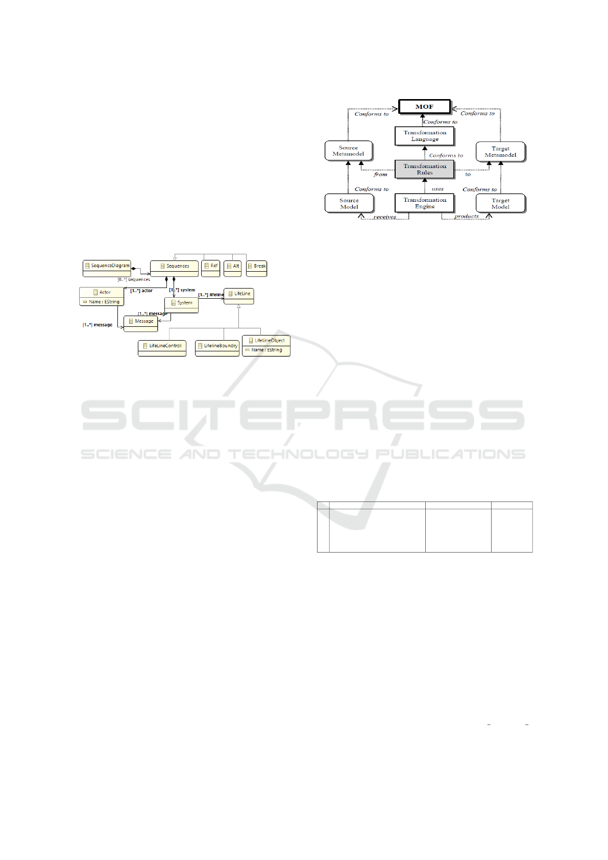
Figure 5 represents the meta-model of sequence
diagram.
Figure 5: Main fragments of System Sequence Diagram
Meta-model.
4.3 Transformation Rules
In this section, we will define different transforma-
tion rules that allow the automatic generation of PIM
level from CIM level. The transformation process
proposed takes as input source models, applies trans-
formation rules, and generate target models. This
process is conform to MOF (Model Object Facility)
(MOF, 2009)which is an OMG standard that allow de-
scribing metamodels and their manipulation. The fig-
ure 6 illustrates the process of model transformation.
A model transformation is like a function that takes as
input parameters a set of models and returns in output
another set of models. Those models, input and out-
put, are structured by meta-models that specify the
model transformation executed on models. There are
two types of transformations:
• M2M: Model to Model transformation which is
defined at the highest levels of MDA approach and
aims to transform models to another models that
contain more information.
• M2T: Model to Text transformation which is ded-
icated to the code generation. It is executed to the
PSM level to generate source code.
In this paper, we will focus on the first type of trans-
formations, Model to Model (M2M), that we divided
in two main sets of transformations:
Figure 6: Relationship between the model transformation
and meta-models.
• UCD&SBVR2BCD (Use Case Diagram and
SBVR to Business Class Diagram): Transforma-
tions that allow the generation of Business Class
Diagram from Use Case Diagram and SBVR.
• UCD&SBVR2SSD (Use Case Diagram and
SBVR to System Sequence Diagram): Transfor-
mations that allow the generation of System Se-
quence Diagram from Use Case Diagram and
SBVR. Next sections will present in details each
of these sets of transformations.
4.3.1 UCD&SBVR2BCD Transformations
UCD&SBVR2BCD is a vertical transformation that
aims to generate a Business Class Diagram from both
a Use Case Diagram and the OMG standard SBVR.
The table 1 describes these transformations:
Table 1: Transformation rules to get Business Class Dia-
gram from UCD and SBVR.
N Rules Source Model Target Model
1 Actor2Class Actor Class
2 DataObject2Class DataObject Class
3 isOfPropertyFactType2Attribute isOfPropertyFactType Attribute
4 associativeFactType2Association AssociativeFactType Association
5 structuralBusinessRule2Cardinality StructuralBusinessRule Cardinality
6 operativeBusinessRule2Operation OperativeBusinessRule Operation
Transformation rules defined in the table above
can be described as follow:
• Transformations from Use Case Diagram:
1. Actor2Class: The Actor element in Use Case
Diagram is turned into a Class element in Busi-
ness Class Diagram.
2. DataObject2Class: The DataObject element in
Use Case Diagram is turned into a Class ele-
ment in Business Class Diagram.
• Transformations from Semantic Business Vocab-
ulary and Business Rules:
3. isOfPropertyFactType2Attribute:”is property of”
fact type element is transformed to an Attribute
MDI4SE 2017 - Special Session on Model-Driven Innovations for Software Engineering
372
of a Class, this element is expressed by
”is property of” or by ”has”, as described in
the following figure 7.
Figure 7: is property of fact type example.
4. associativeFactType2Association : the asso-
ciation fact type, which is expressed by verb,
is turned into an association with the same
verb between classes, the figure 8 describes an
example of associative fact type.
Figure 8: Associative fact type example.
5. structuralBusinessRule2AssociationsEnd:
structural business rules formulated by a neces-
sity or a possibility are turned into Cardinality
as shown in figure 9 below:
Figure 9: Cardinality example.
6. operativeBusinessRule2Operation: operative
business rules formulated by an obligation or
a permission are turned into operations of the
class.The name of the operation is the verb
of the fact type on which the business rule is
based, while parameters are generated from the
two concept types linked by the verb used in
the fact type, we mention that concept types in
our approach are linked to Actor and DataOb-
ject elements in Usecase Diagram, as described
in figure 10:
Figure 10: Class operation example.
4.3.2 UCD&SBVR2SSD Transformations
UCD&SBVR2SSD is a vertical transformation that
aims to generate System Sequence Diagram from
both Use Case Diagram and OMG standard SBVR.
The table 2 describes these transformations:
Table 2: Transformation rules to get System Sequence Dia-
gram from UCD and SBVR.
N Rules Source Model Target Model
1 UseCaseDiagram2SystemLifeLine Actor SystemLifeLine
2 Actor2ActorLifeLine Actor ActorLifeLine
3 DataObject2DataObjectLifeline DataObject DataObjectLifeline
4 UseCase2Message UseCase Message
5 Extend2OptFragment Extend OptFragment
6 Include2RefFragment Include RefFragment
7 GeneralizationUseCase2AltFragment GeneralizationUseCase AltFragment
Transformation rules defined in the table above,
allow to generate all elements of System Sequence
Diagram from Use Case Diagram while links between
them are extracted from SBVR standard:
1. UseCaseDiagram2SystemLifeLine: The Use
Case Diagram is turned into a SystemLifeLine in
the System Sequence Diagram generated.
2. Actor2ActorLifeline: The Actor element in Use
Case Diagram is turned into an ActorLifeLine ele-
ment in the System Sequence Diagram generated.
3. DataObject2DataObjectLifeline: The DataObject
element in Use Case Diagram is turned into a
DataObject Lifeline element in the System Se-
quence Diagram generated.
4. UseCase2Message: A UseCase element is trans-
formed to message between elements of System
Sequence Diagram. There are several types of
messages, but at this stage of our approach, we
need just two types; created message and reply
message . The difference between them is de-
duced from SBVR.
5. Extend2AltFragment : An extend association be-
tween Use Case elements is transformed into an
optional fragment (Opt) in the SSD generated.
6. Include2RefFragment: An include association be-
tween Use Case elements is transformed into a
reference fragment (Ref to other sequence dia-
gram) in the SSD generated.
7. GeneralizationUseCase2AltFragment: the gener-
alization association between Use Case elements
Tool Support to Automate Transformations between CIM and PIM Levels
373

is turned into an alternative fragment (Alt) in the
SSD generated.
The synchronization between messages can be ex-
tracted from Business vocabulary and Business rules,
indeed we can easily express this with conditions and
different Business rules defined by SBVR and based
on associative fact type in Business vocabulary; when
an actor sends request to the system, the system an-
swers according to the request previously received,
the figure 11 describes ans example of interaction be-
tween an actor and the system.
Figure 11: Example of actions synchronization using Busi-
ness rules.
In the figure above we describe an example on
how actions will be synchronized in sequence dia-
gram. For example, the customer receives catalog
after sending the request. In our approach we aim
to generate for each Use Case element a System Se-
quence Diagram. For every Use Case element we de-
fine automatically elements in links with it: Actors,
DataObjects, and other Use Case elements through
different types of associations (extend, include, gener-
alization) which define the interaction between differ-
ent fragments of System Sequence Diagrams. More-
over we separate two types of Use Case elements:
Use Case elements that define functionalities allowed
for an actor, this type is linked through an association
with Actor, and transformed into Sequence Diagram
(System Sequence Diagram). The second type con-
tains Use Case elements that describe how the first
type of Use Case elements is realized. It defines se-
quence diagram that is linked to the first one accord-
ing to the type of association that linked them (In-
clude, Extend, Generalization) in Use Case Diagram
as we mention before.
Usecase elements that are transformed to mes-
sages ensure the interaction between Sequence Dia-
gram elements. There are several types of messages,
but according to our approach we use the following:
• ”Synchronous Message” which is a simple mes-
sage between lifeline elements.
• ”Message Create”: this type of message creates
a new lifeline in the diagram, in our approach it
is used to generate a DataObject which is linked
with a simple association with a Usecase element.
• ”Reply Message”: this kind of message are gener-
ated to reply to previous message, it is generated
from business rule that contains an if condition
and is based on Associative FactType.
5 IMPLEMENTATION OF OUR
APPROACH
To implement our approach we need tools that allow
to create input elements (UML diagrams and SBVR).
After analyzing and testing existing tools, we found
that those which allow to create diagram doesnt offer
an SBVR editor. The unique tool that support SBVR
is an eclipse plug-in called Vetis which was imple-
mented for an old version of Eclipse to support SBVR
standard. Other components of input elements can
be realized through different designer eclipse plug-in.
In our case, we choose Papyrus because it supports
all UML diagrams elements. According to this, we
choose to implement our solution as an eclipse plug-
in to benefit from the existing tools and also to facili-
tate the use of our implemented solution by designers
and developers.
5.1 Papyrus Modeling Tool
Papyrus is an Open Source UML tool based on
Eclipse. It was developed by the Laboratory of Model
Driven Engineering and Embedded Systems and can
be used as a standalone tool or as an Eclipse Plug-in.
Papyrus is designed to be easily extensible because it
is based on UML profile.(Papyrus, 2010)
In our approach we used Papyrus as an Eclipse
plug-in that we extend to support DataObject ele-
ments in Use case Diagram. As papyrus is based
on EMF (Eclipse Modeling Framework) tool that al-
lows creating UML diagrams, we start by extending
the EMF plug-in to define DataObject element and its
specifications to be used by Use Case Diagram, and
then we configure Papyrus in order to add DataOb-
ject element in Use Case Diagram, so that it can be
accessible from the palette menu.
5.2 Vetis Plug-in
Vetis tool was implemented to support transforma-
tions from SBVR to UML&OCL. It was based on
Eclipse platform 3.4.1 and it supports UML 2.0, and
SBVR 1.0 and ATL, in our approach we use Vetis
plug-in to recognise SBVR elements and their struc-
ture.(Nemuraite et al., 2010)
Using Vetis plug-in in our approach was to benefit
from the editor of SBVR standard.
MDI4SE 2017 - Special Session on Model-Driven Innovations for Software Engineering
374
5.3 Our Eclipse Plug-in
Plug-in is a software component used in computing
that adds a specific functionalities and features to an
existing computer program. The plug-in we have de-
veloped, defines transformations rules based on QVT
(Query View transformation). These rules are auto-
matically executed from a Java program.
The plug-in takes as input a Papyrus Project that
contains one or more UML Use Case Diagrams mod-
eled using Papyrus tool and Business Vocabulary and
Business Rules expressed using SBVR standard. The
Transforms feature added in the menu, allow the ex-
ecution of transformations defined automatically. As
result of transformations an out folder is created in
the Papyrus Project that contains the output generated
diagrams: Business Class Diagram and System Se-
quence Diagrams.
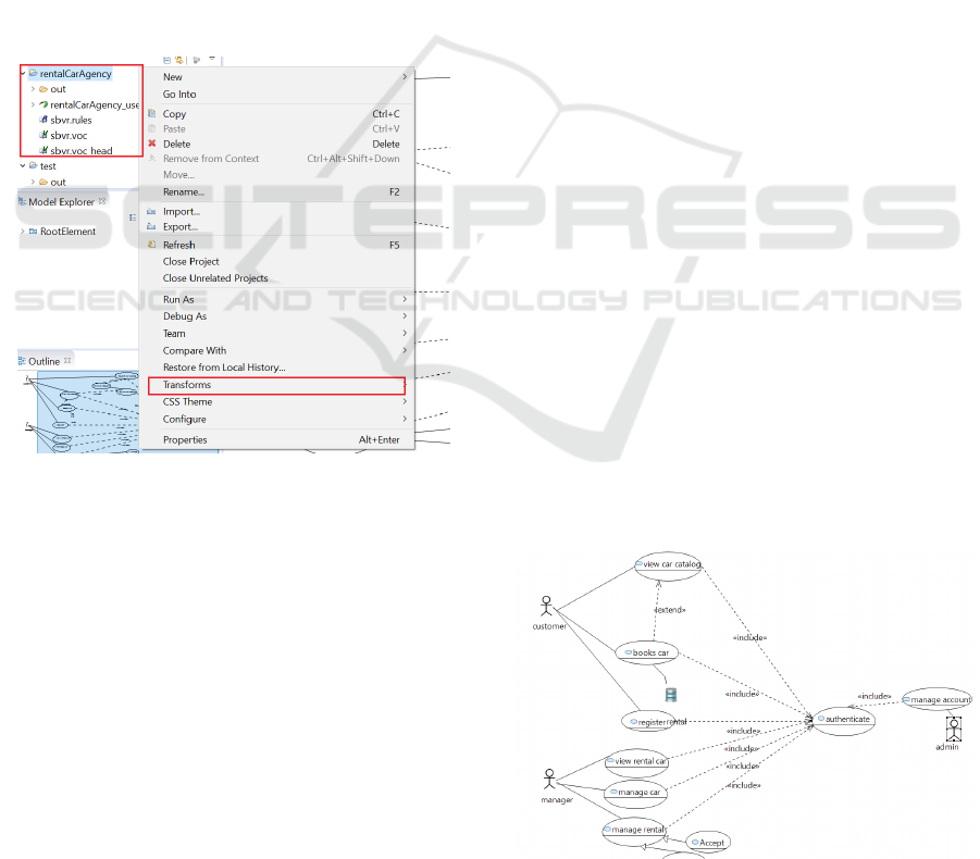
The figure 12 below shows the transforms menu
and the architecture of Papyrus project.
Figure 12: Papyrus project architecture and ”Transforms”
menu.
6 CASE STUDY
In order to illustrate our approach and the transfor-
mation rules defined, this section shows how to apply
the approach on a RentalCarAgency application. The
example is described as follow: The application to re-
alize must guarantee the following services:
• Visualization of available cars.
• Customers subscription.
• Booking of cars.
• Visualization of reservations.
• Management of reservations (accept/decline).
• Management of cars.
• Management of customer accounts.
• Management of accounts Managers.
The application have three users profiles that have dif-
ferent privileges :
• customer: Person who can view the cars avail-
able in the agency, rates and promotions and may
subscribe. Once registered, the visitor becomes a
client of the Agency. A client must authenticate in
the system to search for available cars and book a
car by indicating the reservation date and time.
• Manager: A Manager must also authenticate to
view all cars, add, edit or remove cars and view
the bookings made by customers waiting for vali-
dation to decide to accept or refuse them.
• Administrator: Once authenticated into the sys-
tem, the administrator has the privilege of modify-
ing and deleting a customer account, as well as the
management of managers account (add, change or
delete).
We can define some management rules as below:
• A customer can rent several cars.
• A car can be rented by or several customers.
• A manager can manage 1 or more cars.
• A car is managed by 1 or more managers.
• An administrator can manage 1 or several cus-
tomer accounts.
• An administrator can manage 1 or more account
managers.
After analyzing the application requirements, the
user have to model those requirements in CIM level of
MDA by an Extended Use Case Diagram, we present
our conception of the Use Case Diagram of the appli-
cation in the figure 13
Figure 13: Papyrus project architecture and ”Transforms”
menu.
Tool Support to Automate Transformations between CIM and PIM Levels
375
In the same level of MDA; CIM designer must de-
scribes all requirements vocabulary and their corre-
sponding transformation rules, we present in follow-
ing figures 14 and 15.
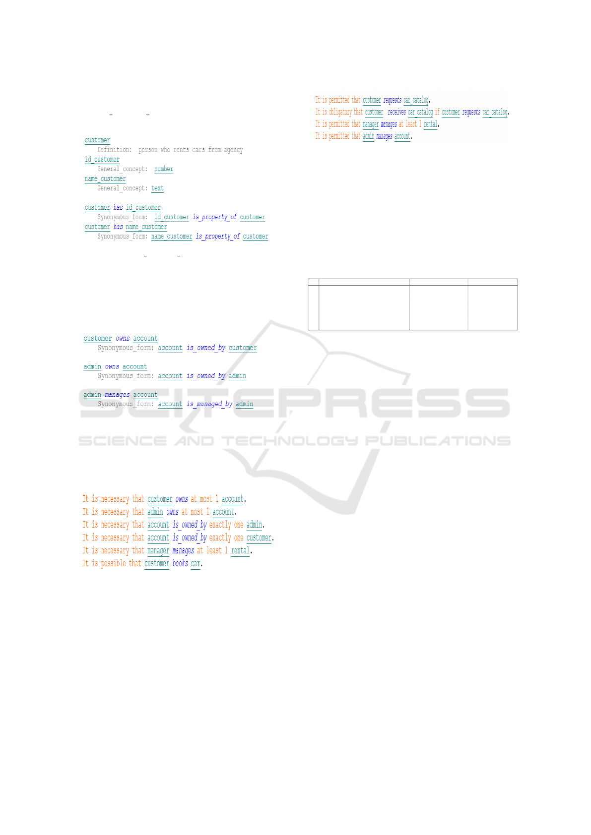
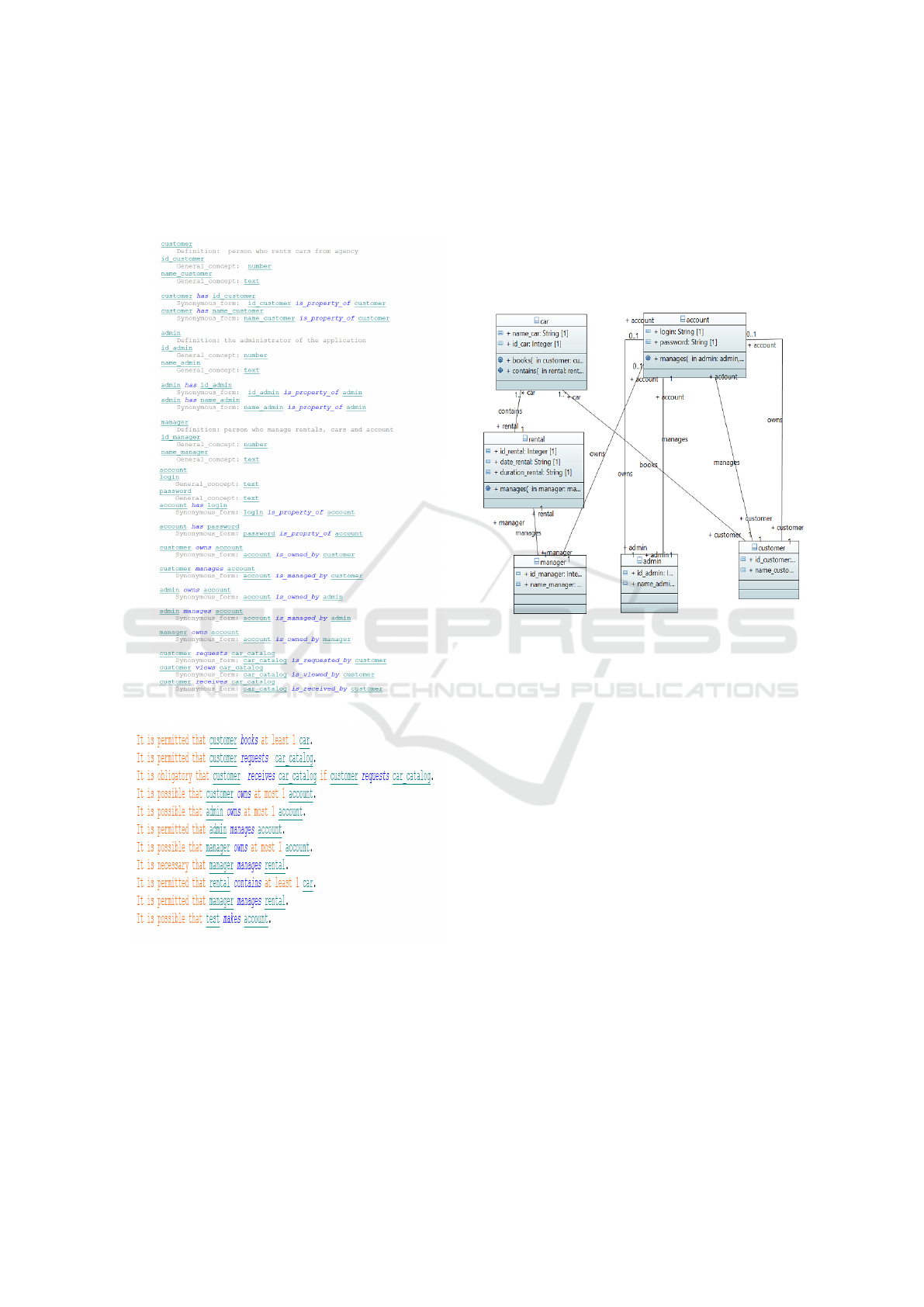
Figure 14: Business Vocabulary of RentalCarAgency.
Figure 15: Business rules of RentalCarAgency.
The PIM level of MDA is generated automatically,
this level is represented by two diagram: Class Di-
agram (Business Class Diagram) that represents the
Structured aspect of the PIM and the several Sequence
Diagrams (System Sequence Diagrams) for each Use-
Case element to cover the dynamic aspect of MDA.
Structured Business Rules are defined by two spe-
cific terms; Possible and Necessary, in our approach
each business rule, defined as a possibility or a neces-
sity based on a specific associative fact type, allows
to generate association ends for the association gen-
erated from the associative fact type.
Executing transformation rules, we generate Busi-
ness Class Diagram of the system, the figure 16 repre-
sents the result automatically generated from previous
diagrams.
Figure 16: Generated Business Class Diagram of Rental-
CarAgency.
Comparing the generated Class Diagram pre-
sented in the figure 16 and the table 4 we conclude
that our tool generate all the elements of class dia-
gram (Classes, attributes,operation, association, ...).
The same execution generates also different Sys-
tem Sequence Diagrams for each UseCase element, as
we explained before we separate two types of Usecase
element, in the following we will detail some Use-
Case element from RentalCarAgency example, we
choose ”view car catalog” to detail different concepts;
extend with ”‘book car”’ and include with ”Authenti-
cate”, we will also generate ”Authenticate” sequence
diagram to clarify the interaction between actor and
system, and finally we chose ”manage rental” to rep-
resent in order to show the integration of generaliza-
tion association in the diagram.
Executing transformation rules, we generate dif-
ferent Sequence Diagram of the system, figure 17, 18,
19 represent the result automatically generated from
previous diagrams of ”Authenticate”, ”View car cata-
log” and ”Manage rental”.
MDI4SE 2017 - Special Session on Model-Driven Innovations for Software Engineering
376
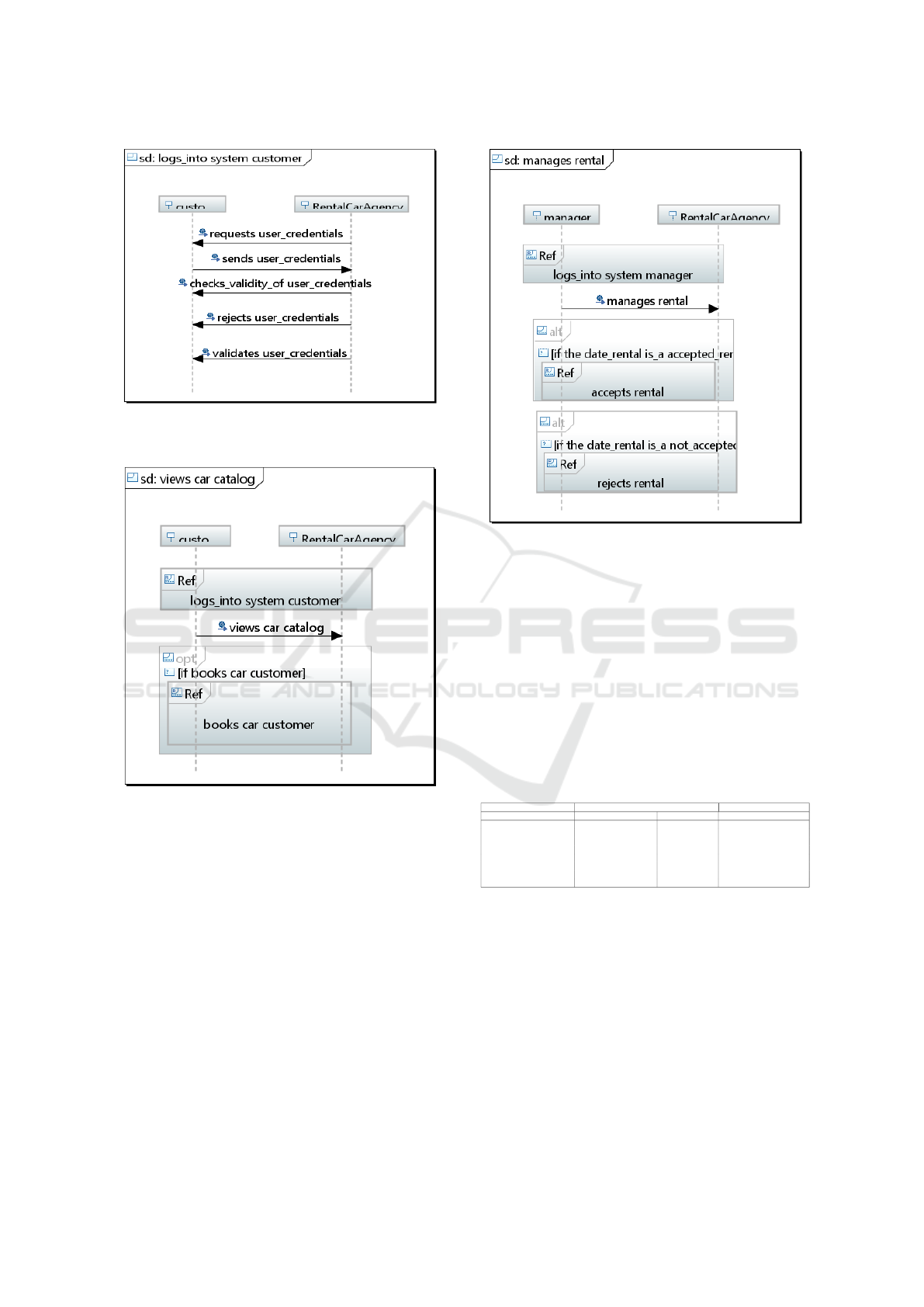
Figure 17: Generated ”Authenticate” Sequence Diagram of
RentalCarAgency.
Figure 18: Generated ”View Catalog” Sequence Diagram
of RentalCarAgency.
7 ANALYSIS AND DISCUSSION
To evaluate our approach we devote this section to
make a comparison between results of existing ap-
proach and ours, the comparison is made according
two areas; Model transformation of CIM to PIM and
transformation of SBVR to UML diagrams.
For the first area; CIM to PIM transformations, the
comparison is made according to proposed transfor-
mation rules, automation of transformations and their
traceability. The second area, the comparison is made
according to transformations rules and their automa-
tion.
We present in the Table 5 below a summary of
Figure 19: Generated ”Manage Rental” Sequence Diagram
of RentalCarAgency.
the analysis done on our approach and the existing
methods ,previously presented in related works sec-
tion of this paper. For each work, we study if it cov-
ers or not all CIM level aspects (Functional, Static
and Dynamic), all PIM level aspects(Structured and
Dynamic), and for the transformations between CIM
and PIM levels, if rules are provided (P for partially,
Y for Yes and N for No) but also their automation
and traceability. As shown in Table 5, even if (Kri-
Table 3: Analyse and discussion of different approach of
CIM to PIM transformations.
Methods CIM level PIM level CIM to PIM transformations
Functional Static Dynamic Structured Dynamic Rules Automation traceability
Addamssiri and al. Y Y Y N Y P N P
Kherraf and al. N N Y Y N P N N
Kriouile and al. Y Y Y Y Y P N N
Kardo and al. N N N Y Y N N N
Wu and al. Y Y Y Y Y P N N
Raj and al. Y N Y Y Y P N N
Bousetta and al. Y Y Y Y Y P P P
Essebaa and al. (Current Approach) Y Y Y Y Y Y Y Y
ouile and al.) and (Wu and al.) approaches cover all
CIM and PIM aspects, they partially define transfor-
mations from CIM to PIM and do not provide automa-
tion neither traceability. Our approach is the unique
one that besides covering CIM and PIM aspects, pro-
vide transformation rules between CIM and PIM, au-
tomate them and allow their traceability.
In the next Table 6, we summarize the analysis
done on our approach and previously existed one that
transform SBVR to UML diagrams. We study if pro-
posed methods ensure transformation rules to gener-
ate UML form SBVR and if these rules are imple-
Tool Support to Automate Transformations between CIM and PIM Levels
377

mented automatically.
Table 4: Analyse and discussion of different approach of
SBVR to UML transformations.
Methods SBVR to UML transformations
Rules Automation
Arfeen and al. P N
Raj and al. P N
Nemuraite and al. P N
Essebaa and al. (current approach) Y Y
As we show in the Table 6 all presented approach
even if they partially define transformation rules but
they didn’t ensure their automation. Our approach
provides transformation rules to generate two UML
diagrams; Class Diagram and Sequence Diagram, and
implements these rules in an eclipse plug-in to ensure
their automation
8 CONCLUSION
The primary objective of this paper is to propose
an approach that covers all the OMG aspects of the
highest levels of abstraction in the MDA approach,
CIM and PIM, and automate transformations between
them. Indeed in our approach we model the CIM level
by a Use Case Diagram and OMG standard SBVR.
Those models cover all the aspects of CIM: func-
tional, static and dynamic. The PIM level in our ap-
proach is generated automatically from CIM and it
is represented by Class Diagram to cover the CIM
structured aspect and different Sequence Diagrams to
cover the dynamic aspect.
In this paper, we also present transformation rules
that were implemented in an Eclipse plug-in in order
to ensure the automatic generation of the PIM level
from the CIM level. The proposed tool is based on
Papyrus eclipse plug-in that allows the design of dif-
ferent UML diagrams, and Vetis plug-in that offers an
SBVR editor which recognize all SBVR elements.
The present paper proposes an optimized and ex-
tended approach of our previous works and we aim in
our future works to cover other MDA levels Transfor-
mations: From PIM to PSM and then from PSM to
code in order to develop a tool that automate all these
transformations. We also plan to apply our approach
on more projects in order to evaluate the developed
tool.
REFERENCES
(2008). Toward an automatic approach to get pim level from
cim level using qvt rules. In Semantics of Business
Vocabulary and Business Rules (SBVR).
(2009). Omg, meta object facility
(mof)2.0query/view/transformation specification.
In http://www.omg.org/spec/QVT/1.0/PDF.
(2011). In OMG Unified Modeling LanguageTM (OMG
UML), Superstructure.
Afreen, H., Bajwa, I. S., and Bordbar, B. (2011). Sbvr2uml:
A challenging transformation.
A.Kriouile, N.Addamssiri, T. (2015). An mda method for
automatic transformation of models from cim to pim.
volume 4.
A.Kriuouile, T.Gadi, Y. (2013). Cim to pim transformation:
A criteria based evaluation. In Int.J.Computer Tech-
nology and Applications, pages 616–625.
B. BOUSETTA, EL BEGGAR Omar, G. T. (2013). A
methodology for cim modelling and its transforma-
tion to pim. In Journal of Information Engineering
and Applications.
Essebaa, I. and Chantit, S. (2016). Toward an automatic ap-
proach to get pim level from cim level using qvt rules.
In 2016 11th International Conference on Intelligent
Systems: Theories and Applications (SITA), pages 1–
6.
Essebaa, I. and Chantit, S. (2017). QVT Transformation
Rules to Get PIM Model from CIM Model, pages 195–
207. Springer International Publishing, Cham.
J.Osis (1969). Topological model of system functioning. In
Automatics and Computer Science., pages 44–50.
Kardo, M. and Drozdov, M. (2010). Analytical method of
cim to pim transformation in model driven architec-
ture (mda). volume 34, pages 89–99.
Kherraf, S., Lefebvre, E., and Suryn, W. (2008). Transfor-
mation from cim to pim using patterns and archetypes.
Miller, J. and Mukerji, J. (2003). Mda guide version 1.0.1.
N.Addamssiri, A.Kriouile, Y.Balouki, and T.Gadi (2014).
Generating the pim behavioral model from the cim us-
ing qvt.
Nemuraite, L., Skersys, T., Sukys, A., Sinkevicius, E., and
Ablonskis, L. (2010).
Ovchinnikova, V. and Nazaruka, E. (2016). The validation
possibility of topological functioning model using the
cameo simulation toolkit. pages 327–336.
Papyrus (2010). In Papyrus.
Raj, A., Prabhakar, V., T., Hendryx, and Stan (2008). Trans-
formation of sbvr business design to uml models.
pages 29–38. ACM.
Sharifi, H. R. and Mohsenzadeh, M. (2012). A new method
for generating cim using business and requirement
models. volume 2, pages 8–12.
Soley, R. (2000). Model driven architecture (mda). In
http://www.omg.org/cgibin/doc?omg/00-11-05,.
Solomencevs, A. (2016). Topological functioning model for
software development within mda (survey). ENASE
2016, pages 315–326.
Wu, J. H., Shin, S. S., Chien, J. L., Chao, W. S., and Hsieh,
M. C. (2007). An extended mda method for user inter-
face modeling and transformation. pages 1632–1641.
MDI4SE 2017 - Special Session on Model-Driven Innovations for Software Engineering
378
