
Meaning of Cause-and-effect Relations of the Topological
Functioning Model in the UML Analysis Model
Erika Nazaruka
Department of Applied Computer Science, Riga Technical University, Sētas iela 1, LV-1048, Riga, Latvia
Keywords: System Modelling, System Analysis, Topological Functioning Model, Cause-and-Effect Relations,
Associations, UML.
Abstract: Topological Functioning Model specifies functional and structural characteristics of a system in the holistic
manner. Cause-and-effect relations link cause and effect functional characteristics of the system, illustrating
causality in it. The Unified Modelling Language (UML) provides its own relationship kinds among
elements. Traditionally, a use of UML relationships depends on analyst’s experience in UML and
knowledge about the system. However, after TFM transformation meaning of cause-and-effect relations in
UML model is not always clear. The paper summarizes research results on this matter and provides
mapping guidelines from TFM causal relations to often used UML relationships. These guidelines can be
applied in further (manual or automated) refinement of UML diagrams.
1 INTRODUCTION
Principles of Model Driven Architecture (MDA) has
opened a very interesting perspective of automated
software model transformations from analysis
models to code. In MDA terms analysis and design
models are called platform independent and platform
specific models correspondingly. There are plenty
researches of code generation from platform specific
models and transformations from platform
independent to platform specific models. But the
question about automated transformation of domain
knowledge to the analysis/design model, i.e. from a
computation independent model to a platform
independent or platform specific one is still open.
According to (Miller and Mukerji, 2001), a
computation independent model (CIM) represents a
system in a form of domain models, business
models, domain vocabulary, or system requirements.
Usually, it is expressed as structured or unstructured
text or semi-formal modelling languages (Singh and
Sood, 2010; Siqueira and Silva, 2012) such as
Unified Modelling Language (UML) and Business
Process Model and Notation (BPMN) that could
cover several or all viewpoints on the system, i.e.
static, behavioural, and functional (Kriouile et al.,
2013).
Speaking about dedication of the CIM to
software development, one of its major goals is to
bridge a real (business, problem) domain with its
corresponding software solution. Achievement of
this goal is difficult (but not impossible), since
requires a use of formal languages or formal models
instead of semiformal models and text at the very
beginning of development. This goal could be
achieved by using a Topological Functioning Model
(TFM) that bridge the problem and solution domains
via formalism provided by the algebraic topology
and system theory, it is discussed in detail in (Osis et
al., 2007a).
The TFM is a formal mathematical model that
allows modelling and analysing functionality of the
system (Osis and Asnina, 2011c). The system could
be a business system, software, biological system,
mechanical system, etc. The TFM represents its
functionality as a digraph
, Θ
, where X is a set of
inner functional characteristics (called functional
features) of the system, and Θ is a topology set on
the characteristics in a form of a set of cause-and-
effect relations. TFM models can be compared for
similarities using continuous mapping mechanism
(Asnina and Osis, 2010).
The open question is about transformation of
cause-and-effect relations into associations between
classes in analysis/design models, since as it is
illustrated in (Osis and Asnina, 2011c; Donins et al.,
336
Nazaruka, E.
Meaning of Cause-and-effect Relations of the Topological Functioning Model in the UML Analysis Model.
DOI: 10.5220/0006384403360345
In Proceedings of the 12th International Conference on Evaluation of Novel Approaches to Software Engineering (ENASE 2017), pages 336-345
ISBN: 978-989-758-250-9
Copyright © 2017 by SCITEPRESS – Science and Technology Publications, Lda. All rights reserved

2011; Asnina et al., 2013) the causality semantics is
of many forms that create two types of a flow,
namely, a control flow and a data flow. The
continuous mapping mechanism can drive
discovering of structural relationships between
domain objects.
This paper summarizes several research results
and gives guidelines on transformation of cause-and-
effect relations to control flows and structural
relationships between domain objects modelled
using UML types of relationships.
Section 2 describes the related work in CIM to
PIM transformations. Section 3 discusses findings in
transformation of cause-and-effect relation within
Topological Functioning Modelling for MDA
(TFM4MDA), TopUML and Integrated Domain
Modelling (IDM) approaches, and provides mapping
guidelines from TFM causal relations to UML
relationships. At the end, conclusions and further
directions for research are outlined.
2 RELATED WORK
The CIM can be presented in the form of Data Flow
Diagram (DFD) and transformed to use case
diagrams, activity diagrams, sequence diagrams and
domain diagrams, which are the base for further
obtaining of class diagrams (Kardoš and Drozdová,
2010). In this research, the transformation to
behaviour diagrams allows correct mapping to
control flows between activities, messages between
objects, but a mapping to domain diagrams is
incomplete. It allows defining concepts and
navigations among them, but information about
structural relationships and multiplicity must be
added by the modeler.
The authors in (Kriouile et al., 2013) have
investigated results of several research papers on
CIM to PIM transformations. The presented results
showed that transformation to class diagrams
requires additional refinements, since usually after
the transformation it provides “a first sketch of the
system structure” and lacks such important details as
class operations, multiplicities in associations,
structural relation types as well as relations. The
authors underline that the CIM must cover all three
aspects of the system, namely, behavioural,
functional and static. Their research of
transformation from the BPMN model to use cases
(Kriouile et al., 2015) to behavioural and domain
classes models resulted in complete acquisition of
control flows and message flows, however, the
domain classes model contains only aggregation
relationships obtained from the BPMN pools and
lanes (Kriouile et al., 2014). The same source and
target models are presented in (Bousetta et al.,
2013), and the transformation to the domain classes
model is supported by using of structural business
rules that allow keeping knowledge about terms and
facts, as well as relations among them. This allows
getting necessary static knowledge such as names of
classes, compositions and aggregations among them,
generalization/specialization relationships,
navigations, and multiplicity in associations in semi-
automatic way. Additionally, the knowledge about a
list or a set of some terms can be expressed as a
constrain in Object Constraint Language (OCL). The
business rules are presented using a subset of natural
languages, thus trying to avoid ambiguity.
Authors in (Rhazali et al., 2015; Rhazali et al.,
2016) transform CIM represented in form of use
case and activity diagrams to the class diagram,
where control flows of the activity diagrams are
transformed to bidirectional navigations with many-
to-many multiplicity in the class diagram. Further
refinement requires human participation.
Transformation from BPMN diagrams to UML
class diagrams and state diagrams for each class
presented in (Mokrys, 2012) also requires additional
participation of a modeler in order to refine
relationships among classes.
Authors in (Kherraf et al., 2008) have proposed
application of patterns to structure of a CIM and a
set of four archetypes that drive generation of a PIM.
In their approach, a CIM model consists of the
business process model (manual and automated) and
the requirements model that specifies activities that
should be automated to support the business
activities. The business process model contains also
data objects. The requirements model is a model of
use cases expressed by means of UML activity
diagrams. A use case is transformed into a process
component that is linked with various entity
components. Links are bidirectional without any
additional information but roles. The roles are
presented as four archetypes: Moment-Interval that
usually corresponds to a process component, and
PPT (Party, Place, Thing), Role and Description that
correspond to an entity component.
The authors in (Essebaa and Chantit, 2016)
similarly to (Bousetta et al., 2013) formalize
business rules and requirements that allow them
getting constraints in OCL, but instead of a subset of
a natural language they use SBVR (Semantic of
Business Rules and Vocabulary) standard. The CIM
consists of a use case model extended with data
objects and business rules in SBVR. The static
viewpoint of the PIM is represented by a class
diagram, however elements in it are linked with
bidirectional associations, and requires additional
refinement.
Meaning of Cause-and-effect Relations of the Topological Functioning Model in the UML Analysis Model
337
Summarizing results of related work, the
conclusion is that static viewpoint of the system
represented as a [domain] class diagram in many
approaches proposed is limited with relationships
obtained from control flows at the CIM level. It is
possible to derive aggregation and composition
(from BPMN models), and (intuitive) bidirectional
navigation between domain classes. More advanced
characteristics such as a specific navigation,
multiplicity and roles in associations as well as
generalization/specialization must be added
manually or explicitly defined in business rules
specified in formalized natural language, i.e. by
using a predefined subset of a natural language or in
the form of SBVR statements.
3 MEANING OF CAUSE-AND-
EFFECT RELATIONS
3.1 Topological Functioning Model
The TFM is a formal mathematical model that has
been first introduced by Janis Osis in 1969 at Riga
Technical University (RTU), Latvia (Osis, 1969).
Several decades this model has been dedicated for
mathematical specification of functionality of
complex mechanical systems (Osis and Asnina,
2011c), but since 1990s it is being elaborated for
software development (Solomencevs, 2016).
The TFM represents system functionality in a
holistic manner as a CIM (Asnina and Osis, 2011). It
describes the functional and structural aspects of the
software system in the form of a directed graph
(X, Q), where a set of vertices X depict functional
characteristics of the system named in human
understandable language, while Q is a set of edges
that depict causal relations (topology) between them.
Such specification is more perceived, precise and
clearer then the large textual descriptions. The TFM
is characterized by the topological and functioning
properties (Osis and Asnina, 2011b). The
topological properties are connectedness,
neighbourhood, closure, and continuous mapping.
The functioning properties are cause-and-effect
relations, cycle structure, inputs, and outputs. The
composition of the TFM is presented in (Osis and
Asnina, 2011c).
Rules of composition and derivation processes
within TFM4MDA from the textual system
description is provided by examples and described in
detail in (Asnina 2006b; Osis et al. 2007b; Osis et al.
2008). The TFM can also be generated automatically
from the business use case descriptions, which can
be specified in the IDM toolset (Šlihte and Osis,
2014). It also can be manually created in the TFM
Editor from the IDM toolset.
Speaking about TFM element, a functional
feature represents some system’s functional
characteristic, e.g., a business process, a task, an
action, or an activity (Osis and Asnina, 2011b). It
can be specified by a unique tuple (1) (Osis and
Asnina, 2011c).
<A, R, O, PrCond, PostCond, Pr, Ex> (1)
Where (1):
A is object’s action,
R is a set of results of the object’s action (it is an
optional element),
O is an object that gets the result of the action or
a set of objects that are used in this action,
PrCond is a set of preconditions or atomic
business rules,
PostCond is a set of post-conditions or atomic
business rules,
Pr is a set of features providers, i.e. entities
(systems or sub-systems) which provide or
suggest an action with a set of certain objects,
Ex is a set of executors (direct performers) of the
functional feature, i.e. a set of entities (systems
or sub-systems) which enact a concrete action.
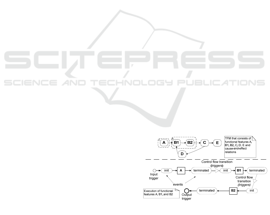
The cause-and-effect relations between functional
features define the cause from which the triggering
of the effect occurs.
The formal definition of the cause-and-effect
relations and their combinations are given in (Asnina
and Ovchinnikova, 2015). It states that a cause-and-
effect relation is a binary relationship that links a
cause functional feature to an effect functional
feature. In fact, this relation indicates control flow
transition in the system (
Figure 1).
Figure 1: The execution of the functional feature instance
(Nazaruka et al., 2016).
The cause-and-effect relations (and their
combinations) may be joined by the logical
operators, namely, conjunction (AND), disjunction
MDI4SE 2017 - Special Session on Model-Driven Innovations for Software Engineering
338
(OR), or exclusive disjunction (XOR). The logical
relation denotes system execution behaviour (e.g.,
decision making, parallel or sequential actions).
The TFM can be manually (but according to the
precise rules) transformed into most used UML
diagram types: use cases (Osis and Asnina, 2011a)
and others (Donins et al., 2011).
3.2 Cause-and-Effect Relations in
TFM4MDA, TopUML and IDM
The TFM4MDA has been developed as an approach
for computation independent modelling within the
MDA. The main idea is that the TFM can serve as a
foundation for domain knowledge modelling,
software requirements verification according to
them, and identification of a use case model and a
conceptual class diagram (Osis et al., 2008).
The TFM4MDA gives a set of characteristics of
a cause-and-effect relation (Asnina et al., 2013;
Asnina & Osis 2010): time dimension, causal
connections allow exceptions in operation,
sufficiency and necessity for generation of effects, a
series of parallel or serial factors involved, and the
universality.
During transformation from the TFM to a use
case model, cause-and-effect relations of the TFM
are transformed to control flows between activities
in UML activity diagrams that serve as use case
specifications (Osis and Asnina, 2011a).
The TFM4MDA provides also transformation to
a conceptual class diagram. However, the conceptual
diagram holds relations between classes, but it is
assumed to be bidirectional. In order to make these
relations more accurate, the topological graph can be
transformed into a sketch (a special form of
representation for Universal Categorical Logic
(Diskin et al., 2000)), then refined, and represented
as a refined conceptual class diagram.
Such transformation also indicates possible
inheritance relations among types and common
operations, which can be further transformed into
interface classes (Osis nd Asnina, 2008). The
underlying logic is discussed in (Asnina, 2006a),
where it is stated that while refining simplified
functional features of the topological functioning
model G(X, ) to the specialized ones of the G*(X*,
*) the following significant case can occur: “If a
functional feature x
i
of the G (X, ) is continuously
mapped onto functional features x
j
*, …, x
n
* of the
G*(X*, *), they specify the same action over
objects of different types and do not have cause-and-
effect relations between them, then this case
indicates a possible inheritance relation between an
object of the x
i
and objects of the specialized
functional features x
j
*, …, x
n
*”.
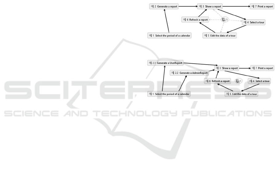
For example, if there is a part of the TFM for
some actions on the report (
Figure
2) that has a
functional feature 2 “Generate a report” with action
“generate” on an object of type “Report”. During
modelling, functional feature 2 is continuously
mapped onto both functional features 2.1 “Generate
a UserReport” and 2.2. “Generate a AdminReport”
in the refined TFM (
Figure
3). Feature 2.1 and 2.2.
do not have cause-and-effect relations among them.
Therefore, it could be assumed that types
UserReport and AdminReport are subtypes of the
type Report.
Figure 2: The TFM for modelling some actions on reports.
Figure 3: The refined TFM for modelling some actions on
reports.
Otherwise, if there are functional features x
j
, …, x
n
of the G(X, ) which specify the same action over
objects of different types and may have cause-and-
effect relations between them, then this case
indicates a possible interface class that can be
realized by objects of these types. For example, if
only the TFM in
Figure
3 exists, then objects of types
UserReport and AdminReport could realize the same
interface class with operation generate().
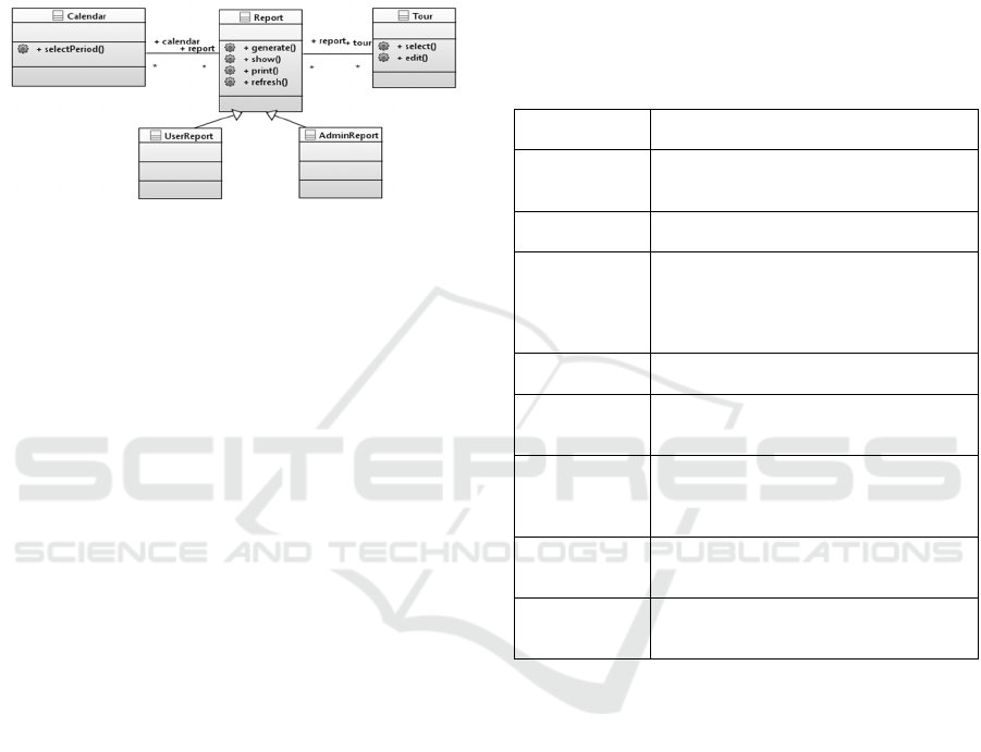
In the TFM4MDA, the decision about other
structural relations (aggregations, dependencies,
directed associations) among object classes must be
made by an analyst in accordance with the problem
domain description and some additional analysis.
The sketch approach that implements the Universal
Categorical Logic can serve as a formal background
for that decision making. For example, in case of the
TFM defined in two levels of abstraction (
Figure
2
and
Figure
3), the produced class diagram would
look like in
Figure
4.
The Topological UML (TopUML) is a language
that extends UML metamodel with the concept of a
Meaning of Cause-and-effect Relations of the Topological Functioning Model in the UML Analysis Model
339
topological relation and a topological functioning
model, and modifies a use case diagram and a class
diagram to the topological use case diagram and
topological class diagram correspondingly. The
TopUML approach explicates the idea of getting
behavioural and structural diagrams from the TFM
and uses TopUML language for modelling the
system in the prescribed order (Donins, 2012).
Figure 4: The produced class diagram within the
TFM4MDA.
In contrast with the TFM4MDA, the TopUML
considers that cause-and-effect relations in the TFM
are not equal to associations in the UML class
diagram (Table 1). The TopUML extracts a
topological relation as a separate type of relations
between UML constructs (Donins et al., 2011;
Donins et al., 2012). Table 1 summarizes how
topological relations are defined in TopUML
diagrams in comparison with the UML diagrams as
it is stated in (Donins, 2012). It approves the
statement made in the TFM4MDA that a topological
relation should be mapped to the control flow (a
control flow, a message, and a transition) when
analyse behaviour of the system. The topological
relation in the use case diagram indicates the
direction in which triggering occurs. The unclear is
how to define meaning of the topological relation in
the class diagram.
Let us consider definitions of the topological
relationship and operation stated in (Donins, 2012):
The topological relationship is “a binary
relationship that shows a cause-and-effect
relation between two elements – the source
element and the target element. A topological
relationship is assertion that indicates that the
effect element can be triggered only by the cause
element thus showing that effect element is
executed only after the cause element executes”.
Topological operation is a “behavioural feature
of classifier that specifies the name, type,
parameters, and constraints for invoking an
associated behaviour, and related functional
features and topological relationships for
specifying cause-and-effect relations within
system, thus allowing cause-and-effect relations
to be modelled within the system by means of
behavioural”.
The TopUML author distinguishes UML and TFM
relationship objectives, so “the topological
relationship defines the causality within Topological
class diagram while association defines the structure
of … classes” (Donins, 2012). However, as related
work shows, some structural characteristics depend
on interaction between elements.
Table 1: Cause-and-effect relations in UML and TopUML.
TopUML
Diagram
Extension to UML Diagrams
Topological
class diagram
Topological relationship is introduced for
modelling cause-and-effect relations
between classes
Activity
diagram
Topological relationship is mapped to the
control flow from one node to another
Topological use
case diagram
Topological relationship is introduced to
show “formally defined communication
between a use case and an actor, showing
who is triggering the communication”
(Donins, 2012)
State diagram
Topological relationship is mapped to the
transition relationship between states
Sequence
diagram
Topological relationship is mapped to a
message sending from one lifeline to
another
Communication
diagram
Topological relationship is mapped to a
message sending from one lifeline to
another (the same construct as in the
sequence diagram)
Interaction
overview
diagram
Topological relationship is mapped either
to the control flow or to the message
between lifelines
Timing
diagram
Topological relationship is mapped to the
message sent between lifelines that cause
changes in their states or conditions
Integrated Domain Modelling (IDM) is an
approach that explicates the TFM4MDA and
TopUML approaches (Šlihte and Osis, 2014). The
main idea is to generate the TFM from structured
text fragments, i.e. textual use case specifications,
and validate knowledge obtained from use cases
against domain ontology (Fernández Céspedes et al.,
2015). Ontology must represent declarative domain
knowledge in the form suitable for computer
processing.
The IDM also provides guidelines for
transformation from the TFM to the UML class
diagram, however, this approach avoid defining any
kind of relationships between classes (Solomencevs
and Osis, 2015).
MDI4SE 2017 - Special Session on Model-Driven Innovations for Software Engineering
340
3.3 Mappings from Cause-and-effect
Relations to UML Relationships
Summarizing results from all the three approaches,
namely, TFM4MDA, TopUML and IDM, the
following guidelines for determination of meanings
of cause-and-effect relations in UML diagrams can
be stated.
UML behavioural diagrams (the behavioural
view on the system):
Activity Diagram – a direct mapping to the
control flow as it is defined in the TopUML;
State Diagram – a direct mapping to the
transition relationships as it is defined in the
TopUML;
Sequence Diagram – a direct mapping to the
messages between lifelines as it is defined in the
TopUML;
Communication Diagram – a direct mapping to
the messages between lifelines as it is defined in
the TopUML;
Interaction Overview Diagram – a direct
mapping to the messages between lifelines or to
the control flow as it is defined in the TopUML;
Timing Diagram – a direct mapping to the
message sent between lifelines that causes
changes in their states or conditions as it is
defined in the TopUML;
Use case diagram (in some approaches it is
considered as the functional view on the system)
– here the topological use case model can serve
as an intermediate model or transformation step
that could help in determining a direction of
communication between an actor and a use case
as well as to identification of extensions and
inclusions.
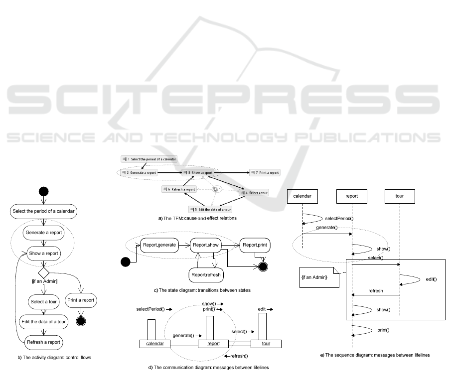
The transformation from the TFM in Figure 2 to the
first four behavioural diagrams is illustrated in Figure
5
. Fragments in ellipses show how a cause-and-
effect relation from functional feature 2 “Generate a
report” to functional feature 3 “Show a report” (part
a) is transformed to the control flow between
activities “Generate a report” and “Show a report” in
the activity diagram (part b); to the transition
relationship between two states of the object Report,
namely, “generate” and “show” (part c); to the
messages between lifelines calendar:Calendar and
report:Report in the communication diagram (part d)
and in the sequence diagram (part e).
The UML class diagram (the structural view on
the system):
Generalization/Specialization – a structural
relationship that can be defined in case if there is
a set of specialized functional features, which
actions specify the same action over objects of
different types as a functional feature at the
higher level of abstraction does for its object and
they do not have cause-and-effect relations
between themselves (as it is stated in the
TFM4MDA). The illustrating example was
discussed in Section 3.2.
Figure 5: Transformation from the TFM to the activity, state, sequence and communication diagrams.
Meaning of Cause-and-effect Relations of the Topological Functioning Model in the UML Analysis Model
341
Realization between classes and interfaces – it
comes from the determination of
generalization/specialization. If several
functional features at the same level of
abstraction have the same action for different
types of objects, then this action can be extracted
to the interface class. However, if these
functional features are continuously mapped to
the functional feature at the higher level of
abstraction, then this indicates rather on different
implementations of the superclass operation (the
refined guideline stated in the TFM4MDA).
Navigation and Association – a kind of
behavioural relationship that can be obtained
from the analysis of directions of cause-and-
effect relations among functional features with
the object of the concrete type and functional
features with the objects of other types: in case if
all cause-and-effect relations among the
mentioned functional features have the same
direction, this indicates the navigation;
otherwise, it is the association. This statement is
based on the results that come from the
TopUML, namely, these two relationships
indicates on calls of the operations which in case
of sequence and communication diagrams are
direct mappings from the cause-and-effect
diagrams to the messages between object
lifelines.
Roles – a characteristic that may come either
from the domain knowledge or be just
automatically created based on the domain object
type (class name) and some automatic
incremental number generator.
Aggregation and Composition – a structural
relationship that should be obtained from the
domain knowledge (as further elaboration of the
idea proposed in the IDM).
Dependency – a kind of behavioural relationship
for event-driven system, where an event is a
special case of action. Thus, “event” is a
characteristic of the action that may come from
the domain knowledge (as further elaboration of
the idea proposed in the IDM).
Multiplicity – a characteristics that should be
obtained from the domain knowledge (as further
elaboration of the idea proposed in the IDM).
In case of realization of interfaces, determination of
navigations, associations and, partially, roles, the
necessary knowledge can be obtained from the TFM
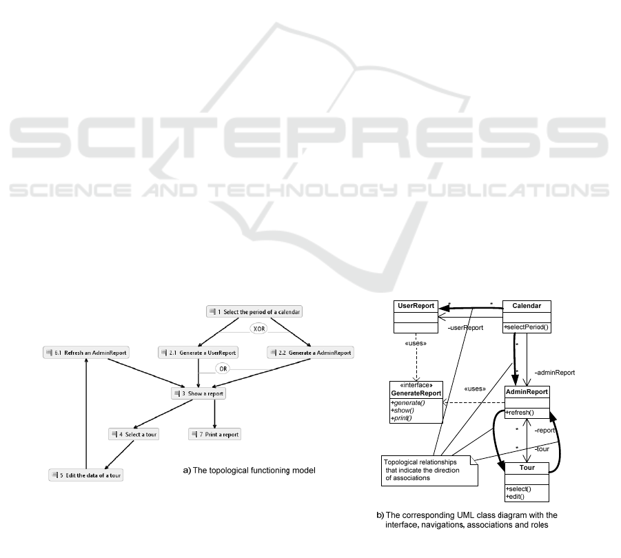
as illustrated in Figure 6.
Here we have two object types UserReport and
AdminReport (part a) that are transformed to two
classes with the same names (part b). Functional
features 3 and 7 of the TFM are feature sets that
holds functionality for both these objects. Therefore,
it is possible to extract this functionality to the
interface class with operations generate(), show(),
print(). However, operation refresh() can be
assigned only to AdminReport. Certainly, further
analysis can lead to including this operation to the
same interface class.
Bold arrows denote directed cause-and-effect
relations between classes. Their direction is applied
to associations by indicating navigable ends of them,
i.e. in case of topological relationship from Calendar
to UserReport it is possible to map it to a navigation
from Calendar to UserReport. In the presented
example (Figure 6, part b) roles are generated from
the names of classes related to each other by
association or navigation.
Figure 6: The UML class diagram (b) obtained from the TFM (a).
MDI4SE 2017 - Special Session on Model-Driven Innovations for Software Engineering
342

Other structural characteristics of relationships
between domain objects, i.e. aggregation,
composition, multiplicity and dependencies, are pure
declarative knowledge. Therefore, the idea of
keeping them in domain ontology that could be
proceeded during transformation is very promising.
Summarizing, the abovementioned mappings
illustrate that it is possible to get most of the often-
used types of UML relationships when transforming
from the TFM to the analysis model. In case of
structural relationships and characteristics of objects
or actions, the declarative knowledge on the domain
should be used. This knowledge can be represented
as ontology according to the idea provided in the
IDM.
4 CONCLUSIONS
The overview of the related work showed that in
many proposed approaches the transformation to the
behavioural diagrams is mostly successful, however
structural diagrams are limited with the aggregation
and composition obtained from the BPMN model for
several data objects (mainly representing pools and
lanes within it), and intuitive associations between
domain classes. Other relationships that represent
generalization/specialization, specific navigations,
multiplicities and roles must be added manually or
predefined in business rules.
The overview of three approaches, namely,
TFM4MDA, TopUML and IDM, that make
transformations to and from the TFM showed that
there is the same weakness regarding to structural
diagrams. Generalizations/specializations between
classes and realizations between classes and
interfaces can be generated after analysis of TFM
abstraction levels. Besides that, transformation from
the TFM to the class diagram suggests keeping the
cause-and-effect relations between classes. Thus,
navigations and associations could be obtained by
analysis of directions of cause-and-effect relations.
To get other structural information, there is a
necessity to hold declarative knowledge about the
domain in some computational format, e.g.
ontology. The ontology should be useful for
automated generation of aggregations, compositions,
dependencies, multiplicities as well as roles that
depend on the context.
The future research is dedicated to
implementation and validation of automation of the
proposed guidelines and domain ontology to get the
more complete class diagram that should be in
conformity to other (behavioural) diagrams of the
system under consideration.
REFERENCES
Asnina, E., 2006a. Formalization of Problem Domain
Modeling within Model Driven Architecture. Riga
Technical University.
Asnina, E., 2006b. The Computation Independent
Viewpoint: a Formal Method of Topological
Functioning Model Constructing. Applied computer
systems, 26, pp.21–32.
Asnina, E. & Osis, J., 2010. Computation Independent
Models: Bridging Problem and Solution Domains. In
Proceedings of the 2nd International Workshop on
Model-Driven Architecture and Modeling Theory-
Driven Development. Lisbon: SciTePress - Science
and and Technology Publications, pp. 23–32.
Asnina, E. & Osis, J., 2011. Topological Functioning
Model as a CIM-Business Model. In Model-Driven
Domain Analysis and Software Development. Hershey,
PA: IGI Global, pp. 40–64.
Asnina, E., Osis, J. & Jansone, A., 2013. Formal
specification of topological relations. In Frontiers in
Artificial Intelligence and Applications. Amsterdam:
IOS Press, pp. 175–188.
Asnina, E. & Ovchinnikova, V., 2015. Specification of
decision-making and control flow branching in
Topological Functioning Models of systems. In
ENASE 2015 - Proceedings of the 10th International
Conference on Evaluation of Novel Approaches to
Software Engineering. Lisbon: SciTePress, pp. 364–
373.
Bousetta, B., Beggar el, O. & Gadi, T., 2013. A
methodology for CIM modelling and its
transformation to PIM. Journal of Information
Engineering and Applications, 3(2), pp.1–21.
Available at: www.iiste.org [Accessed February 17,
2017].
Diskin, Z. et al., 2000. Universal Arrow Foundations for
Visual Modeling. In V. H. M. Anderson, P. Cheng, ed.
Diagrams’2000: Proc. 1st Int. Conference on the
theory and application of diagrams, Edinburgh
(Scotland), UK, Sept. 1-3, 2000. LNAI#1889. Springer,
pp. 345–360. Available at:
http://www.cs.toronto.edu/~zdiskin/pubs-in-
ChronOrder.htm [Accessed February 21, 2017].
Donins, U. et al., 2012. Formal analysis of objects state
changes and transitions. In ENASE 2012 - Proceedings
of the 7th International Conference on Evaluation of
Novel Approaches to Software Engineering. Lisbon:
SciTePress, pp. 249–256.
Donins, U., 2012. Topological Unified Modeling
Language: Development and Application. Riga
Technical University.
Donins, U. et al., 2011. Towards the refinement of
topological class diagram as a platform independent
model. In A. Čaplinskas et al., eds. Proceedings of the
3rd International Workshop on Model-Driven
Architecture and Modeling-Driven Software
Development, MDA and MDSD 2011, in Conjunction
with ENASE 2011. Vilnius: Žara, pp. 79–88.
Meaning of Cause-and-effect Relations of the Topological Functioning Model in the UML Analysis Model
343

Essebaa, I. & Chantit, S., 2016. Toward an automatic
approach to get PIM level from CIM level using QVT
rules. In 2016 11th International Conference on
Intelligent Systems: Theories and Applications (SITA).
Mohammedia: IEEE, pp. 1–6. Available at:
http://ieeexplore.ieee.org/document/7772271/
[Accessed February 17, 2017].
Fernández Céspedes, K.V., Osis, J. & Alksnis, G., 2015.
Lessons Learned by using the Integrated Domain
Modeling Toolset. In Proceedings of the 10th
International Conference on Evaluation of Novel
Approaches to Software Engineering. SCITEPRESS -
Science and and Technology Publications, pp. 352–
363. Available at: doi=10.5220/0005477703520363
[Accessed February 21, 2017].
Kardoš, M. & Drozdová, M., 2010. Analytical method of
CIM to PIM transformation in model driven
architecture (MDA). Journal of Information and
Organizational Sciences, 34(1), pp.89–99.
Kherraf, S., Lefebvre & Suryn, W., 2008. Transformation
from CIM to PIM Using Patterns and Archetypes. In
19th Australian Conference on Software Engineering
(aswec 2008). IEEE, pp. 338–346. Available at:
http://ieeexplore.ieee.org/document/4483222/
[Accessed February 17, 2017].
Kriouile, A. et al., 2014. Getting the static model of PIM
from the CIM. In 2014 Third IEEE International
Colloquium in Information Science and Technology
(CIST). Tetouan: IEEE, pp. 168–173. Available at:
http://ieeexplore.ieee.org/document/7016613/
[Accessed February 17, 2017].
Kriouile, A., Addamssiri, N. & Gadi, T., 2015. An MDA
Method for Automatic Transformation of Models from
CIM to PIM. American Journal of Software
Engineering and Applications, 4(1), pp.1–14.
Available at: doi=10.11648/j.ajsea.20150401.11
[Accessed February 16, 2017].
Kriouile, A., Gadi, T. & Balouki, Y., 2013. CIM to PIM
Transformation: A Criteria Based Evaluation.
Int.J.Computer Technology & Applications, 4(4),
pp.616–625.
Miller, J. & Mukerji, J., 2001. Model Driven Architecture
( MDA ), Available at: http://www.omg.org/cgi-
bin/doc?ormsc/2001-07-01.
Mokrys, M., 2012. Possible transformation from Process
Model to IS Design Model. In ICTIC -
PROCEEDINGS IN CONFERENCE OF
INFORMATICS AND MANAGEMENT SCIENCES.
EDIS - Publishing Institution of the University of
Zilina, pp. 71–74.
Nazaruka, E. et al., 2016. Verification of BPMN Model
Functional Completeness by using the Topological
Functioning Model. In Proceedings of the 11th
International Conference on Evaluation of Novel
Software Approaches to Software Engineering.
Portugal: SCITEPRESS - Science and and Technology
Publications, pp. 349–358. Available at:
doi=10.5220/0005930903490358 [Accessed February
20, 2017].
Osis, J., 1969. Topological Model of System Functioning
(in Russian). Automatics and Computer Science, J. of
Academia of Siences, (6), pp.44–50.
Osis, J. & Asnina, E., 2011a. Derivation of use cases from
the topological computation independent business
model, Hershey, PA: IGI Global.
Osis, J. & Asnina, E., 2008. Enterprise Modeling for
Information System Development within MDA. In
Proceedings of the 41st Annual Hawaii International
Conference on System Sciences (HICSS 2008).
Waikoloa, USA: IEEE, pp. 490–490. Available at:
http://ieeexplore.ieee.org/document/4439190/.
Osis, J. & Asnina, E., 2011b. Is Modeling a Treatment for
the Weakness of Software Engineering? In Model-
Driven Domain Analysis and Software Development:
Architectures and Functions. Hershey, PA: IGI
Global, pp. 1–14.
Osis, J. & Asnina, E., 2011c. Topological Modeling for
Model-Driven Domain Analysis and Software
Development : Functions and Architectures. In Model-
Driven Domain Analysis and Software Development.
Hershey, PA: IGI Global, pp. 15–39.
Osis, J., Asnina, E. & Grave, A., 2007a. Computation
Independent Modeling within the MDA. In IEEE
International Conference on Software-Science,
Technology & Engineering (SwSTE’07). IEEE, pp.
22–34. Available at:
http://ieeexplore.ieee.org/document/4384082/.
Osis, J., Asnina, E. & Grave, A., 2008. Formal Problem
Domain Modeling within MDA. In J. Filipe et al., eds.
Software and Data Technologies: Second
International Conference, ICSOFT/ENASE 2007,
Barcelona, Spain, July 22-25, 2007, Revised Selected
Papers. Berlin, Heidelberg: Springer Berlin
Heidelberg, pp. 387–398. Available at:
http://dx.doi.org/10.1007/978-3-540-88655-6_29.
Osis, J., Asnina, E. & Grave, A., 2007b. MDA oriented
computation independent modeling of the problem
domain. In ENASE 2007 - Proceedings of the 2nd
International Conference on Evaluation of Novel
Approaches to Software Engineering. Barcelona:
INSTICC Press, pp. 66–71.
Rhazali, Y., Hadi, Y. & Mouloudi, A., 2016. CIM to PIM
Transformation in MDA: from Service-Oriented
Business Models to Web-Based Design Models.
International Journal of Software Engineering and Its
Applications, 10(4), pp.125–142. Available at:
http://dx.doi.org/10.14257/ijseia.2016.10.4.13
[Accessed February 16, 2017].
Rhazali, Y., Hadi, Y. & Mouloudi, A., 2015. Disciplined
approach for transformation CIM to PIM in MDA. In
Model-Driven Engineering and Software Development
(MODELSWARD), 2015 3rd International Conference
on. IEEE, pp. 312–320. Available at:
http://ieeexplore.ieee.org.resursi.rtu.lv/xpls/icp.jsp?arn
umber=7323113 [Accessed February 17, 2017].
Singh, Y. & Sood, M., 2010. The Impact of the
Computational Independent Model for Enterprise
Information System Development. International
Journal of Computer Applications, 11(8), pp.21–26.
MDI4SE 2017 - Special Session on Model-Driven Innovations for Software Engineering
344

Siqueira, F.L. & Silva, P.S.M., 2012. Analyzing CIM to
PIM Transformations Using the WRSPM model.
Infocomp, 11(1), pp.41–50.
Solomencevs, A., 2016. Topological Functioning Model
for software development within MDA (Survey). In
ENASE 2016 - Proceedings of the 11th International
Conference on Evaluation of Novel Software
Approaches to Software Engineering. pp. 315–326.
Solomencevs, A. & Osis, J., 2015. The Algorithm for
Getting a UML Class Diagram from Topological
Functioning Model. In Proceedings of the 10th
International Conference on Evaluation of Novel
Approaches to Software Engineering. SCITEPRESS -
Science and and Technology Publications, pp. 341–
351. Available at: doi=10.5220/0005474303410351
[Accessed February 21, 2017].
Šlihte, A. & Osis, J., 2014. The Integrated Domain
Modeling: A Case Study. In Databases and
Information Systems: Proceedings of the 11th
International Baltic Conference (DB&IS 2014).
Tallinn: Tallinn University of Technology Press, pp.
465–470.
Meaning of Cause-and-effect Relations of the Topological Functioning Model in the UML Analysis Model
345
