
Topology Splitting and Matching for Multi-Cloud Deployments
Karoline Saatkamp
1
, Uwe Breitenbücher
1
, Oliver Kopp
2
and Frank Leymann
1
1
Institute of Architecture of Application Systems, University of Stuttgart, Stuttgart, Germany
2
Institute for Parallel and Distributed Systems, University of Stuttgart, Stuttgart, Germany
Keywords:
Application Deployment, Distribution, Splitting, Cloud Computing, TOSCA.
Abstract:
For automating the deployment of applications in cloud environments, a variety of deployment automation
technologies have been developed in recent years. These technologies enable specifying the desired deployment
in the form of deployment models, which can be automatically executed. However, changing internal or external
conditions often lead to strategical decisions that must be reflected in all deployment models of a company’s IT.
Unfortunately, while creating such deployment models is difficult, adapting them is even harder as typically a
variety of technologies must be replaced. In this paper, we present the Split and Match Method that enables
splitting a deployment model following a manually specified distribution on the business layer. The method
also enables automatically deploying the resulting model without the need for a manual intervention and, thus,
significantly eases reflecting strategical decisions on the technical deployment layer. We present a formalization
and algorithms to automate the steps of the method. Moreover, we validate the practical feasibility of the
presented concepts by a prototype based on the TOSCA standard and the OpenTOSCA ecosystem.
1 INTRODUCTION
In recent years, cloud computing gained a lot of at-
tention as it enables a cost-efficient IT operation (Ley-
mann, 2009). To automate the deployment of applica-
tions in cloud environments, a variety of deployment
technologies were developed: Beside powerful cloud
provider APIs that ease deploying applications on the
provider’s services, configuration management tech-
nologies such as Chef and container approaches such
as Docker significantly ease deploying applications.
Moreover, several standards have been published to en-
sure portability and interoperability. One of these stan-
dards, for example, is the TOSCA specification (OA-
SIS, 2013b), which enables creating extensive deploy-
ment models whose execution requires coordinating
multiple of the aforementioned approaches (Wettinger
et al., 2014). Based on these approaches, deployment
models can be created to efficiently automate the de-
ployment of an application in a repeatable manner.
Deployment models are typically created follow-
ing strategical decisions: whether to host an appli-
cation’s frontend on-premise on the local infrastruc-
ture of a company or to outsource it to a cloud needs
careful considerations. However, deployment models
quickly get complex and require intensive technical
knowledge to ensure the models flawless executabil-
ity (Breitenbücher et al., 2013). Changing internal and
external conditions, e.g., outsourcing parts of the com-
pany’s IT or new cloud offerings, often require strate-
gical rethinking about deployment. Thus, if strategies
change, also the deployment models of applications
must be adapted accordingly. Unfortunately, while
creating such models is difficult, adapting them is
even harder as typically a variety of technologies must
be replaced. Therefore, a manual approach is time-
consuming, knowledge-intensive, and error-prone.
In this paper, we tackle these issues. We present a
method for splitting a deployment model following a
manually specified distribution on the business layer.
The method also enables automatically deploying the
resulting model without the need for a manual inter-
vention, thus, significantly eases reflecting strategical
decisions on the technical deployment layer. To enable
the automated split, we present a formalization and
several algorithms. We validate the practical feasibility
of the presented approach by a prototype based on the
TOSCA standard and the OpenTOSCA ecosystem.
The remainder of this paper is structured as fol-
lows. Section 2 motivates our approach while Sec-
tion 3 presents our new method. In Section 4, we
introduce a formalization of deployment models and
present our prototype in Section 5. Section 6 discusses
related work, Section 7 concludes the paper.
Saatkamp, K., Breitenbücher, U., Kopp, O. and Leymann, F.
Topology Splitting and Matching for Multi-Cloud Deployments.
DOI: 10.5220/0006371002750286
In Proceedings of the 7th International Conference on Cloud Computing and Services Science (CLOSER 2017), pages 247-258
ISBN: 978-989-758-243-1
Copyright © 2017 by SCITEPRESS – Science and Technology Publications, Lda. All rights reserved
247
OpenStack
(OpenStack-
Liberty-12)
Ubuntu
(Ubuntu-14.04-
VM)
Apache Web
Server
(Apache-2.4)
Tomcat
(Tomcat)
MySQL-DBMS
(MySQL-DBMS-
5.5)
MySQL-DB
(MySQL-DB)
REST API
(WAR)
PHP Container
(Apache PHP-5-
Module)
PHP WebApp
(PHP-5- Web
Application)
hostedOn
connectsTo
OnPrem AWSPaaS AWSPaaS
Label
ComponentName
(ComponentType)
Figure 1: A topology model for an on-premise hypervisor in
which parts shall be distributed to a public cloud provider.
2 MOTIVATION, BACKGROUND,
AND FUNDAMENTALS
For emphasizing the motivation of this work, a motivat-
ing scenario is presented in this section. The scenario
considers the deployment of a web-based application
and its distribution onto multiple providers. Before
we detail the motivating scenario, we first introduce
some background information about topology models
required for understanding the remainder of this paper.
2.1 Topology Models
The deployment of an application can be modeled as
topology, which is a directed graph consisting of nodes
which represent the components of the application and
edges that represent the relationships between them.
Topology models are used for describing the deploy-
ment of applications, which are then automatically
executed by a runtime. Components and relationships
in topology models are typed to specify the desired
semantics. In addition, topology models typically spec-
ify properties for components and relationships such
as the IP address of a web server to configure the de-
ployment. The TOSCA specification (OASIS, 2013b),
which we use in this work to validate our concepts, is
an official OASIS standard for describing such topol-
ogy models. Throughout this paper, we use the graphi-
cal TOSCA notation VINO4TOSCA (Breitenbücher
et al., 2012) to render topology models graphically.
2.2 Motivating Scenario
Figure 1 shows a topology model describing the de-
ployment of an application. The frontend is a PHP
web application of type PHP 5 Web Application that is
connected to the backend system that exposes a REST
API. The connection is modeled as connectsTo relation,
which in turn has a connectsTo relation to a MySQL-
DB database component. The PHP web application
is deployed in an Apache-2.4 web server. The REST
API is implemented as Java web application (WAR)
running in a Tomcat servlet container. All three layers
are deployed on an Ubuntu-14.04-VM that shall run on
an on-premise OpenStack, which is the infrastructure
component of this deployment model.
Changing internal and external conditions, e.g.,
outsourcing parts of the company’s IT for optimiz-
ing cost, reduction of system administrators, or new
available cloud offerings often require strategical re-
thinking about current deployment strategies. As a
result, applications that have been formerly defined
to run on-premise may need to be redistributed onto
public cloud offerings to save cost or for other rea-
sons. However, manually adapting topology models
for other distributions is an error-prone task if topolo-
gies are complex. This requires significant expertise
about available cloud service offerings and their capa-
bilities to ensure that the application can be deployed
on these services. Moreover, manually checking if
the provided capabilities match the application com-
ponent’s requirements is very time-consuming. There-
fore, we propose an automated approach for splitting
such topology models for multiple providers.
Regarding our scenario, a distribution decision
could be to remain the frontend on-premise due to
existing resources and to relocate the backend to Ama-
zon’s platform services. We depicted this split in the
form of labels in Figure 1 (OnPrem and AWSPaaS). To
enable this distribution, the existing model has to be
split according to the desired target providers. More-
over, besides splitting, adaptations of the resulting
model are required: some components must be added,
others need to be removed. In our example, we need to
inject components for Amazon’s cloud offerings to en-
able the automated deployment of the application: to
deploy the WAR file, a component of type AWS Elastic
Beanstalk must be injected as well as a component of
type Amazon RDS for hosting the database. Moreover,
if this model shall be used for deploying an instance of
the application, it has to be checked if an OpenStack
is currently running on-premise. Otherwise, another
available on-premise hypervisor must be used, which
also requires exchanging nodes in the model. The goal
of our work is to automate all these considerations.
CLOSER 2017 - 7th International Conference on Cloud Computing and Services Science
248
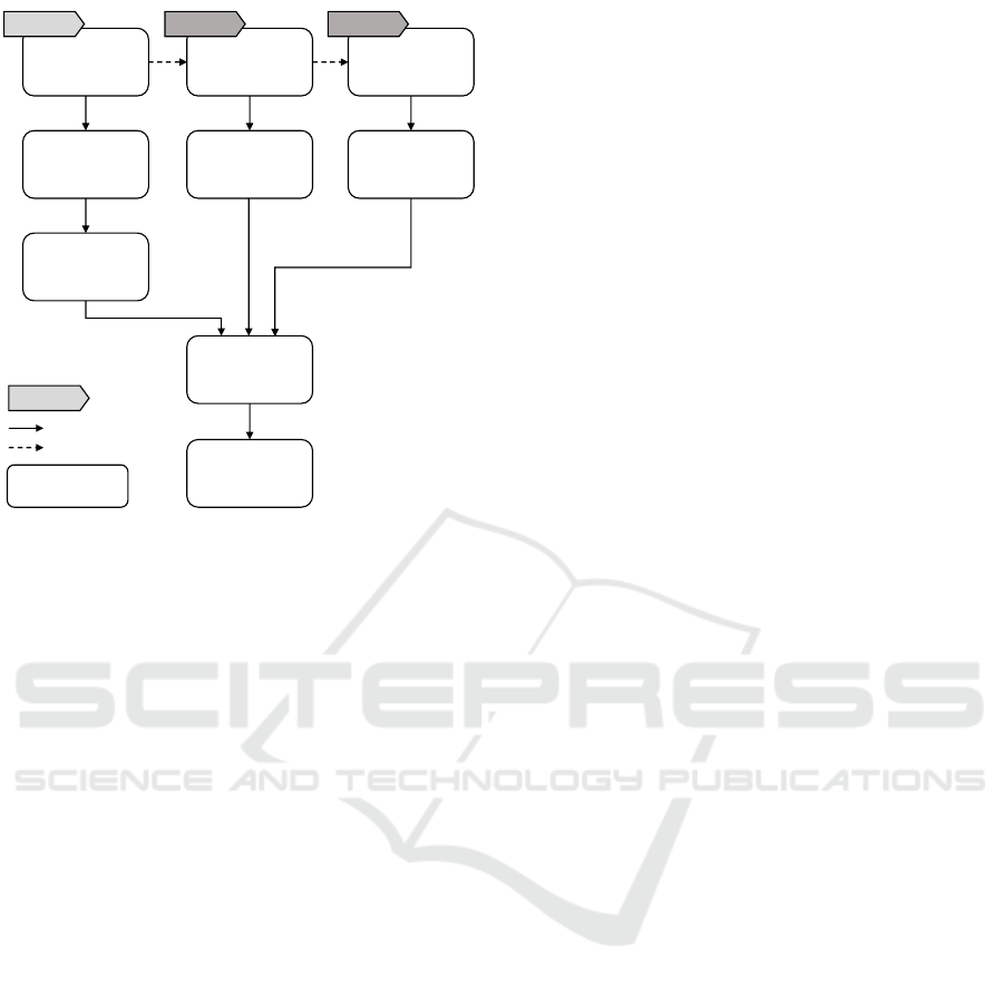
Model
Topology
Add Target
Labels
Validate
Specified Split
Split
Topology
Match Topology
with Target
Deploy
application
1 2 3 4 5 6
1
2
1
2
1
2
1
2
1
2
2
1
2
1
2
1
2
1
Provider
Repositories
Figure 2: Overview of the Split and Match Method.
3 SPLIT AND MATCH METHOD
To deal with the mentioned challenges, we introduce
the Split and Match Method. The method splits a
topology according to the specified targets providers
and matches the resulting topology fragments with
the cloud providers’ services to support an automated
deployment of the application to multiple clouds. Fig-
ure 2 provides an overview of the method.
The goal of the Split and Match Method is to en-
able a customized distribution of the components of
an application to different cloud providers. For each
usage of the application an individual distribution is
possible. The benefits over a distribution-specific mod-
eling are that (1) the final distribution has not to be
known at modeling time and (2) in case the distribu-
tion preferences change, the application can be split
and deployed accordingly in an automated manner.
3.1 Step 1: Model Topology
In the first step, a topology model representing (i) the
components of the application as well as (ii) their rela-
tionships has to be created. As seen in Figure 1, compo-
nents can be, e.g., a PHP web application (application-
specific component), an Apache web server (middle-
ware component), or an OpenStack hypervisor (infras-
tructure component). The application-specific compo-
nents form the highest level of the topology.
In the example depicted in Figure 1, only hostedOn
and connectsTo relationships are used to describe the
relations between components. In this work, we focus
only on these two abstract types as we have found that
they are sufficient to model the general dependencies
between components. Of course, further subtypes, e.g.,
installedOn, that refine the abstract semantics can be
created, too. As they inherit these abstract semantics,
they do not influence the presented algorithms.
3.2 Step 2: Add Target Labels
In the second step, target labels are attached to the
application-specific components. Each target label
specifies the desired target on which the respective
component shall be deployed. In this work, a target
may be a public cloud provider such as Amazon, a pri-
vate cloud, or even a certain virtualization technology
installation such as a running OpenStack. Depending
on the distribution objective, the target can be chosen
on different levels of granularity: The method as well
as the presented algorithms are not restricted to infras-
tructure offerings but can also target, for example, a
platform service such as AWS Elastic Beanstalk
1
.
The distribution and selection of providers can be
specified manually or automatically based on optimal
distribution approaches, for example, as presented by
Andrikopoulos et al. (2014a) . However, the distribu-
tion decision is not part of the method.
3.3 Step 3: Validate Specified Split
In step three, the topology model and the attached
target labels have to be checked on whether or not the
specified splitting is possible. For a valid topology
split, (i) all application-specific components must have
a target label and (ii) all direct or transitive successors
of a component connected by hostedOn relations must
have either the same label or no label assigned. The
reasons for these requirements are as follows: In case
an application-specific component is not labeled, it can
not be matched to a cloud provider. Furthermore, a
component can not be hosted on a component which
is deployed on a different cloud provider. Thus, the
deployment of components connected by hostedOn
relations at the same cloud provider is mandatory. The
modeled split of the motivating scenario in Figure 1 is
valid, i.e., this distribution of the topology is possible.
1
https://aws.amazon.com/de/elasticbeanstalk/
Topology Splitting and Matching for Multi-Cloud Deployments
249
OpenStack_OnP
(OpenStack-
Liberty-12)
Ubuntu
(Ubuntu-14.04-
VM)
Apache Web
Server
(Apache-2.4)
Amazon RDS
(Amazon RDS)
MySQL-DB
(MySQL-DB)
REST API
(WAR)
PHP Container
(Apache PHP-5-
Module)
PHP WebApp
(PHP-5- Web
Application)
onPrem AWSPaaS AWSPaaS
onPrem
onPrem
Beanstalk
(AWS Elastic
Beanstalk)
AWSPaaS AWSPaaS
onPrem
onPrem
OpenStack
(OpenStack-
Liberty-12)
Ubuntu
(Ubuntu-14.04-
VM)
Apache Web
Server
(Apache-2.4)
MySQL-DBMS
(MySQL-DBMS-
5.5)
MySQL-DB
(MySQL-DB)
REST API
(WAR)
PHP Container
(Apache PHP-5-
Module)
PHP WebApp
(PHP-5- Web
Application)
onPrem AWSPaaS AWSPaaS
onPrem
onPrem
Tomcat
(Tomcat)
Ubuntu
(Ubuntu-14.04-
VM)
OpenStack
(OpenStack-
Liberty-12)
AWSPaaS AWSPaaS
AWSPaaS
AWSPaaS
onPrem
onPrem
VSphere OnP
(VSphere)
Openstack OnP
(OpenStack-
Liberty-12)
Amazon RDS
Beanstalk
(AWS Elastic
Beanstalk)
OnPrem
Provider Repo
AWSPaaS
Provider Repo
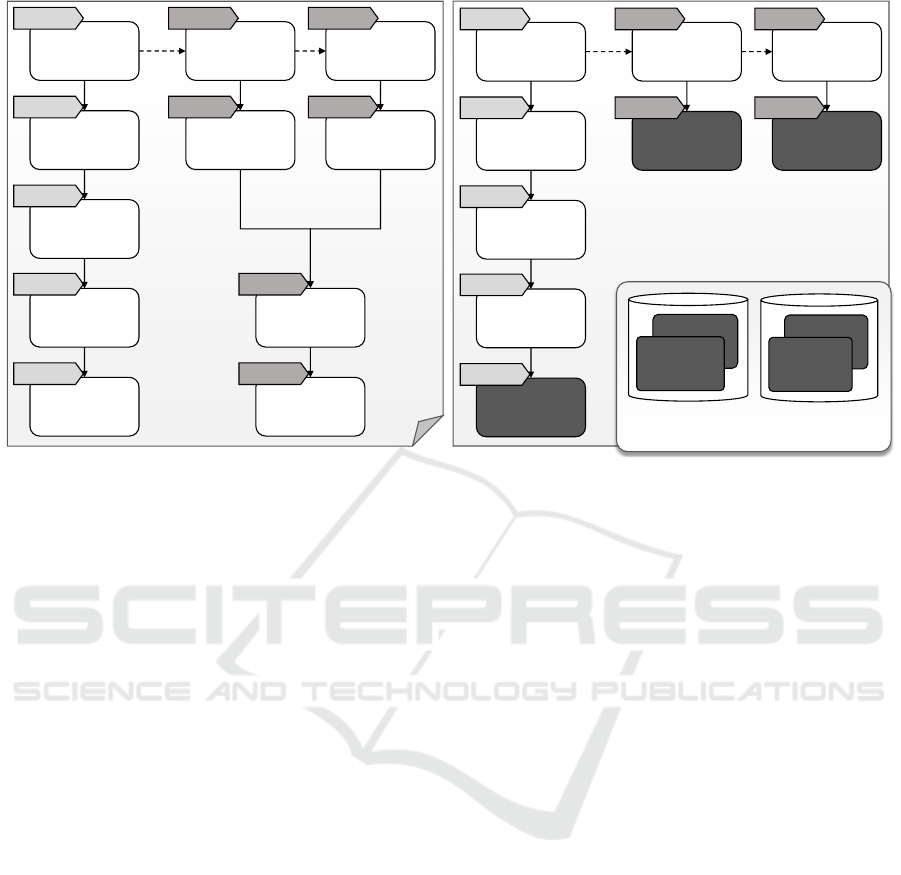
Figure 3: Split topology model (left) and matched topology model (right) based on motivating scenario.
3.4 Step 4: Split Topology
If the verification confirms that the specified distribu-
tion is valid, the topology can be split according to
the target labels. To functionally preserve valid stacks,
each component hosting components with different
labels has to be duplicated for each target label of the
hosted components. The same applies to the relations
of the duplicated components. Applying this to the
motivating scenario results in the split topology model
shown in Figure 3 on the left. Comparing the original
topology model with the split model shows that the
components Ubuntu and OpenStack are duplicated for
each target label. Additionally, the target label of the
application-specific components are propagated down
to the middleware and infrastructure components, so
that this distribution information is available at each
component. In the motivating scenario, the right stack
has been annotated with the target label AWSPaaS but
the infrastructure component is still OpenStack after
the split as shown in Figure 3 and it remains a deploy-
able topology. Nevertheless, this OpenStack will be
replaced in the next step to fulfill the desired target
label of using Amazon’s platform offerings.
3.5 Step 5: Match Topology with Target
In the fifth step, the split model is matched to the
respective providers. Provider Repositories store in-
formation about the types of components a provider
supports. In Figure 3 on the right, two Provider Reposi-
tories are shown: One for Amazon’s platform offerings
containing the components AWS Elastic Beanstalk and
Amazon RDS, the other one contains all components
that are running in the own on-premise infrastructure –
in this case, a locally running OpenStack and VSphere.
The supported components are stored as component
templates that also provide access information, e.g.,
the company’s Amazon account. The repositories are
identified by target labels and, thus, a lookup of com-
ponent templates supported by a provider is possible
to deploy the components having this target label.
The matching procedure under the objective to pre-
serve as much information as possible of the original
topology is as follows. Starting from the bottom com-
ponents upwards, for each component it is checked (i)
if the target provider’s repository contains a template
capable to host the component. If a template can be
found, it is added to the topology. (ii) If former does
not apply, the procedure tries to replace the component
by a template from the provider repository. (iii) If both
do not apply, the component gets removed and the
procedure goes upwards the stack to check this pro-
cedure for the hosted components. The procedure is
repeated until each component either has been replaced
by a template or is hosted on an inserted component
template. In Figure 3 on the right, this matching is
illustrated for the motivating scenario in Figure 1.
3.6 Step 6: Deploy Application
Following the resulting topology model, the compo-
nents are deployed using a deployment system. We
show a possible implementation in Section 5.
CLOSER 2017 - 7th International Conference on Cloud Computing and Services Science
250
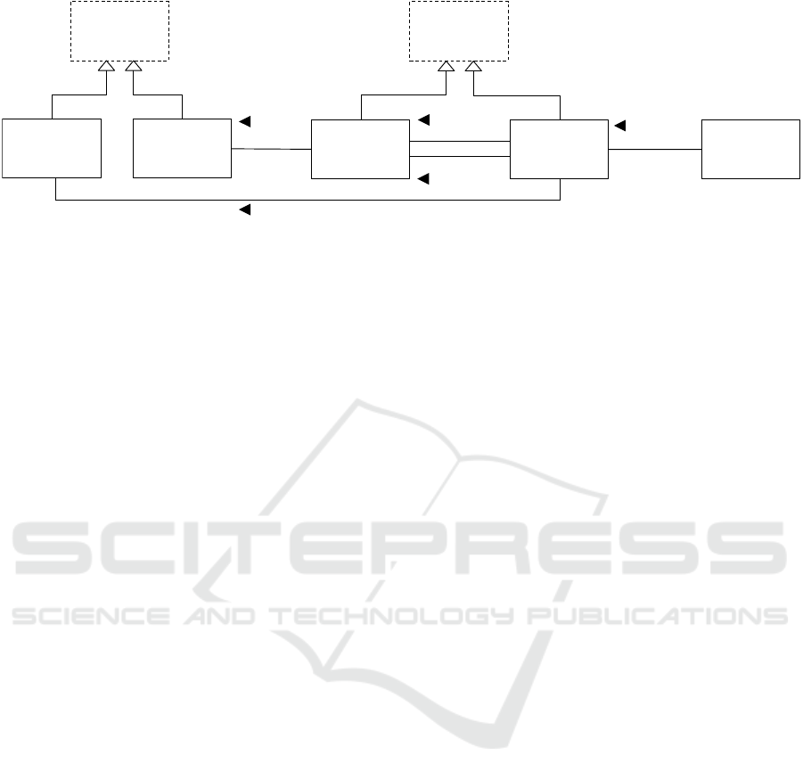
Target Label
Relation
Type
Relation
Component
assigned to
0..1
1
is source of
1
*
is target of
1
*
Component
Type
1
*
is of type
Topology
Element
1
*
is of type
Topology
Element
Type
Figure 4: Metamodel of a topology.
4 FORMALIZATION &
ALGORITHMS
Steps 3 to 5 of the proposed method can be automated.
Algorithms to enable an automated validation check
(step 3), splitting (step 4), and matching (step 5) of
the topology are presented in this section. Based on a
metamodel with a formal definition of a topology and
its elements (Section 4.1), descriptive algorithms are
presented (Section 4.2) which enable the automated
execution. The approach is graph-based and generic
in terms of the complexity of the topology as well as
the concrete cloud providers. The metamodel as well
as the descriptive algorithms are shown in this section.
4.1 Metamodel
The metamodel represents the formal definition of
a topology and its elements. The metamodel is ab-
stracted from the DMMN (Declarative Application
Management Modeling and Notation) metamodel (Bre-
itenbücher, 2016). In order to be independent of a
concrete definition language and to enable the adapta-
tion of this approach to all graph-based languages, the
TOSCA standard has not been chosen as metamodel.
Other approaches such as GENTL (Andrikopoulos
et al., 2014b) are too close to TOSCA or too generic
to be a suitable formalization basis. Figure 4 gives
an overview on the metamodel, which is presented in
the following. Thereby, we render class names of the
metamodel by a starting capital letter.
A Topology is a directed, weighted, and possibly
disconnected graph and describes the structure of an
application. Let
T
be the set of all Topologies, then
t ∈ T is defined as tuple:
t = (C
t
,R
t
,CT
t
,RT
t
,L
t
,type
t
,label
t
) (1)
The elements of the tuple t are defined as follows:
• C
t
: The set of Components in
t
, whereby each
c
i
∈ C
t
represents a component of the application.
• R
t
⊆ C
t
×C
t
: The set of Relations in
t
, whereby
each
r
i
= (c
s
,c
t
) ∈ R
t
represents the relationship
between two of the application’s components:
c
s
is the source and c
t
the target component.
• CT
t
: The set of Component Types in
t
, whereby
each
ct
i
∈ CT
t
describes the semantics for each
Component having this Component Type.
• RT
t
: The set of Relation Types in t, whereby each
rt
i
∈ RT
t
describes the semantics for each Relation
having this Relation Type.
• L
t
: The set of Target Labels in
t
, whereby each
l
i
∈ L
t
specifies the cloud provider a component
can be deployed on.
• type
t
: The mapping, which assigns to each Com-
ponent and Relation of
t
its Component Type and
Relation Type, respectively. Let the set of Topol-
ogy Elements
TE
t
:= C
t
∪R
t
be the union of the set
of Components and Relations of
t
. Let the set of
Topology Element Types
TET
t
:= CT
t
∪RT
t
be the
union of the set of Component Types and Relation
Types of
t
. Then, the mapping
type
t
maps each
te
i
∈ TE
t
to one
tet
j
∈ TET
t
, which specifies the
semantic of the Topology Element.
• label
t
: The mapping, which assigns each Com-
ponent
c
i
∈ C
t
to one or no Target Label
l
j
∈ L
t
:
label
t
: C
t
→ L
t
∪ {⊥}.
Let
L
be the set of all globally available Target
Labels, which may be used to assign Target Labels
to the Components of a Topology t. Let
C T
be the
set of all globally available Components Types and
R T
the set of all globally available Relation Types.
Consequently, the following applies:
L
t
⊆ L
,
CT
t
⊆
C T , and RT
t
⊆ R T .
Based on this metamodel, algorithms are proposed
for validation, splitting, and matching a topology.
Topology Splitting and Matching for Multi-Cloud Deployments
251

Algorithm 1: TopologyValidationCheck(t ∈ T).
1: // Topology is invalid if components without hostedOn-predecessors are not labeled
2: if (∃c
i
∈ C
t
: C
−hostedOn
t
(c
i
) = ∅ ∧ label
t
(c
i
) = ⊥) then
3: return false
4: end if
5: // The transitive closure have to be computed only for the hostedOn relations
6: t
0
:= (C
t
, {r
i
∈ R
t
| type
t
(r
i
) = hostedOn}, CT
t
, {hostedOn}, L
t
, type
t
, label
t
)
7: compute R
+
t
0
8: // Topology is invalid if the transitive closure contains a relation between components with different labels
9: if (∃(c
i
,c
j
) ∈ R
+
t
0
: label
t
0
(c
i
) 6= ⊥ ∧ label
t
0
(c
j
) 6= ⊥ ∧ label
t
0
(c
i
) 6= label
t
0
(c
j
)) then
10: return false
11: end if
12: return true
4.2 Algorithms
For automating steps 3 to 5 of the Split and Match
Method, three algorithms are proposed. They are
based on the metamodel introduced previously.
In addition to the formal definitions in Section 4.1,
a formal definition of the direct predecessors and suc-
cessors of a Component in a Topology
t
is provided.
A predecessor and successor, respectively, is a Com-
ponent which is connected with the Component by a
Relation. The predecessor serves as source and the
successor as target of a Relation.
The set of predecessors of a Component
c
i
∈ C
t
of
a Topology t ∈ T is defined as follows:
C
−
t
(c
i
) = {c
j
∈ C
t
| ∃r
i
∈ R
t
: π
1
(r
i
) = c
j
∧π
2
(r
i
) = c
i
}
(2)
The predecessors of a component connected by a
hostedOn relation, so called hostedOn-predecessors,
are defined as follows:
C
−hostedOn
t
(c
i
) = {c
j
∈ C
t
| ∃r
i
∈ R
t
:
π
1
(r
i
) = c
j
∧ π
2
(r
i
) = c
i
∧type
t
(r
i
) = hostedOn}
(3)
The set of successors of a Component
c
i
∈ C
t
of a
Topology t ∈ T is defined equivalently as follows:
C
+
t
(c
i
) = {c
j
∈ C
t
| ∃r
i
∈ R
t
: π
2
(r
i
) = c
j
∧π
1
(r
i
) = c
i
}
(4)
Thus, the hostedOn-successors are defined as:
C
+hostedOn
t
(c
i
) = {c
j
∈ C
t
| ∃r
i
∈ R
t
:
π
2
(r
i
) = c
j
∧ π
1
(r
i
) = c
i
∧type
t
(r
i
) = hostedOn}
(5)
4.2.1 Topology Validation Check Algorithm
This subsection presents an algorithm, which checks
whether a valid splitting of a given topology is pos-
sible. For the verification of the direct and transitive
successors connected by hostedOn relations the transi-
tive closure is used. It contains all direct and transitive
relations. Let R
+
t
be the transitive closure of R
t
.
The topology validation check is described in Algo-
rithm 1 in pseudo code. The algorithm gets a Topology
t ∈ T
as input. The output is a Boolean value indicating
whether the topology is valid.
First it is checked, if any application-specific com-
ponent is not labeled (lines 1 to 4). Is a label missing
on this level, it is not possible to match this compo-
nent to a cloud provider and, thus, a valid splitting
and matching is not possible. Components on a lower
level in the topology, however, may be unlabeled. Dur-
ing the splitting step, the labels of the highest level
components are propagated to the lower levels.
Secondly, the transitive closure based on the
hostedOn relations are computed (lines 5 to 7). There-
fore, if the transitive closure contains a relation be-
tween two components which have different labels, a
valid splitting is not possible (lines 8 to 11).
A topology is valid, i.e., a splitting is possible,
if all components without hostedOn-predecessors are
labeled and no direct or indirect hostedOn-successor
of a component has a different label assigned (line 12).
4.2.2 Splitting Algorithm
A valid topology can be split according to the target
labels. The splitting procedure is described in Algo-
rithm 2, which gets a Topology
t ∈ T
as input. After-
wards, the split topology is returned.
A working copy
t
0
of
t
is generated (line 1). New
components are added to both, but processed compo-
nents are removed from
t
0
only. To ensure that each
CLOSER 2017 - 7th International Conference on Cloud Computing and Services Science
252

Algorithm 2: Splitting(t).
1: t
0
:= t
2:
// Consider each component whose hostedOn-predecessor components have no further hostedOn-predecessors
3: while (∃c
i
∈ C
t
0
: C
−hostedOn
t
0
(c
i
) 6= ∅ ∧ (∀c
j
∈ C
−hostedOn
t
0
(c
i
) : @c
k
∈ C
−hostedOn
t
0
(c
j
))) do
4: // If all predecessors have the same label assign this label to the considered component
5: if (∃l
i
∈ L
t
0
: ∀c
j
∈ C
−hostedOn
t
0
(c
i
) : label(c
i
) = l
i
) then
6: label
t
(c
i
) := l
i
; label
t
0
(c
i
) := l
i
7: else
8: // Otherwise, duplicate the considered component for each target label
9: for all (l
i
∈ L
t
0
| ∃c
j
∈ C
−hostedOn
t
0
(c
i
) : label
t
0
(c
j
) = l
i
) do
10: let c
new
/∈ C
t
11: C
t
:= C
t
∪ {c
new
}; C
t
0
:= C
t
0
∪ {c
new
}
12: type
t
(c
new
) := type
t
(c
i
); type
t
0
(c
new
) := type
t
(c
i
)
13: label
t
(c
new
) := l
i
; label
t
0
(c
new
) := l
i
14: // Duplicate the relations and assign them accordingly
15: b
1
(r) := ((π
2
(r) = c
i
) ∧ ∀c
j
∈ C
−hostedOn
t
0
(c
i
) : (π
1
(r) = c
j
) ∧ (label
t
0
(c
j
) = l
i
))
16: b
2
(r) := ((π
2
(r) = c
i
) ∧ ∀c
j
∈ C
−hostedOn
t
0
(c
i
) : π
1
(r) 6= c
j
)
17: for all (r
i
∈ R
t
0
: b
1
(r
i
) ∨ b
2
(r
i
)) do
18: r
new
:= (π
1
(r
i
),c
new
)
19: R
t
:= R
t
∪ {r
new
}; R
t
0
:= R
t
0
∪ {r
new
}
20: type
t
(r
new
) := type
t
(r
i
); type
t
0
(r
new
) := type
t
(r
i
)
21: end for
22: for all (r
i
∈ R
t
0
: π
3
(r
i
) = c
i
) do
23: r
new
:= (c
new
,π
2
(r
i
))
24: R
t
:= R
t
∪ {r
new
}; R
t
0
:= R
t
0
∪ {r
new
}
25: type
t
(r
new
) := type
t
(r
i
); type
t
0
(r
new
) := type
t
(r
i
)
26: end for
27: end for
28: // Remove the original component and its relations
29: C
t
:= C
t
\ {c
i
}; C
t
0
:= C
t
0
\ {c
i
}
30: R
t
:= R
t
\ {r
i
| π
1
(r
i
) = c
i
∨ π
2
(r
i
) = c
i
}; R
t
0
:= R
t
0
\ {r
i
| π
1
(r
i
) = c
i
∨ π
2
(r
i
) = c
i
}
31: end if
32:
// Remove the hostedOn-predecessors of the considered component and their relations in the working copy
33: C
t
0
:= C
t
0
\ {c
j
| c
j
∈ C
−hostedOn
t
0
(c
i
)}
34: R
t
0
:= R
t
0
\ {r
j
| ∀c
j
∈ C
−hostedOn
t
0
(c
i
) : π
1
(r
j
) = c
j
∨ π
2
(r
j
) = c
j
}
35: end while
36: return t
label is propagated correctly from the top to the bot-
tom of the topology, each component whose hostedOn-
predecessors have no further hostedOn-predecessors
is considered (line 2 to 35). For the example being
discussed in Figure 1, the PHP container, the Tomcat
servlet container, or the MySQL DBMS component
are considered in any order in the first iteration.
For each considered component the labels of the
hostedOn-predecessors are checked. If all have the
same label, this label is assigned to the component
(line 5-6). Otherwise, the component and its relations
are duplicated for each assigned label (lines 7 to 31).
First of all, the component is duplicated (lines 7 to
13). Then the relations have to be duplicated, so that
all hostedOn-predecessors with the same label are as-
signed to the appropriate duplicate (lines 15 to 21).
The same applies to all other incoming relations (lines
16 to 21) and outgoing relations (lines 22 to 26) of the
original component.
Finally, the original component and its relations
are removed from the topology (lines 28 to 30). This
component will not be considered again in an iteration.
Additionally, the hostedOn-predecessors of the consid-
ered component and their relations are removed from
the working copy t
0
(lines 32 to 34).
After one iteration the duplicated components are
without hostedOn-predecessors. The whole iteration
(lines 3 to 35) is repeated until no more components
with hostedOn-predecessors are contained in t
0
.
Topology Splitting and Matching for Multi-Cloud Deployments
253

Algorithm 3: Matching(t,CR
L
t
).
1: // Matching
t
contains all cloud provider components matched to the topology
2: Matching
t
:= ∅
3:
// Consider each component without hostedOn-successors which can be hosted by a cloud provider component
4: while (∃c
i
∈ C
t
: C
+hostedOn
t
(c
i
) = ∅ ∧ (∃c
new
∈ CR
l
i
: l
i
= label
t
(c
i
) ∧ type(c
k
) ∈ canhost(c
new
))) do
5: if (c
new
/∈ Matching) then
6: C
t
:= C
t
∪ {c
new
}; label
t
(c
new
) := label
t
(c
i
)
7: Matching
t
:= Matching
t
∪ {c
new
}
8: end if
9: // Add a new hostedOn relation
10: r
new
:= (c
i
, c
new
)
11: R
t
:= R
t
∪ {r
new
}; type
t
(r
new
) := hostedOn
12: end while
13: // Try to find for each component without hostedOn-successor a suitable replacement component
14: while (∃c
i
∈ C
t
: C
+hostedOn
t
(c
i
) = ∅ ∧ c
i
/∈ Matching
t
∧ (∀c
j
∈ C
t
: C
−hostedOn
t
(c
j
) 6= ∅)) do
15:
// Find for each predecessor of the component a cloud provider component which can host the predecessor
16: for all (c
k
∈ C
−hostedOn
t
(c
i
)) do
17: b
1
:= (∃c
new
∈ Matching
t
: label
t
(c
new
) = label
t
(c
i
) ∧ type(c
k
) ∈ canhost(c
new
))
18: b
2
:= (∃c
new
∈ CR
l
i
: l
i
= label
t
(c
i
) ∧ type(c
k
) ∈ canhost(c
new
))
19: if (b
1
∨ b
2
) then
20: // If a suitable cloud provider component is already in the matching set take this component
21: if (b
1
) then
22: let c
new
∈ Matching
t
23: else
24: // Otherwise, add a suitable component from the provider repository
25: let c
new
∈ CR
l
i
\ Matching
t
26: C
t
:= C
t
∪ {c
new
}
27: label
t
(c
new
) := label
t
(c
i
)
28: Matching
t
:= Matching
t
∪ {c
new
}
29: end if
30: // Change the target of the hostedOn relation of the considered predecessor
31: for all (r
i
∈ R
t
| π
1
(r
i
) = c
k
∧ π
2
(r
i
) = c
i
)) do
32: π
2
(r
i
) := c
new
33: end for
34: // For the considered component, duplicate all incoming relations not being hostedOn
35: for all (r
i
∈ R
t
| π
2
(r
i
) = c
i
∧ type
t
(r
i
) 6= hostedOn) do
36: r
new
:= (π
1
(r
i
), c
new
)
37: R
t
:= R
t
∪ {r
new
}; type
t
(r
new
) := type
t
(r
i
)
38: end for
39: // For the considered component, duplicate all outgoing relations
40: for all (r
i
∈ R
t
| π
1
(r
i
) = c
i
) do
41: r
new
:= (c
new
, π
2
(r
i
))
42: R
t
:= R
t
∪ {r
new
}; type
t
(r
new
) := type
t
(r
i
)
43: end for
44: end if
45: end for
46: // Remove the original component and all its relations from the topology
47: C
t
:= C
t
\ {c
i
}
48: R
t
:= R
t
\ {r
i
| π
1
(r
i
) = c
i
∨ π
2
(r
i
) = c
i
}
49: end while
50: if (∃c
i
∈ C
t
: C
+hostedOn
t
(c
i
) = ∅ ∧ c
i
/∈ Matching
t
) then
51: // Throw fault because the desired distribution is not possible
52: throw fault
53: end if
54: return t
CLOSER 2017 - 7th International Conference on Cloud Computing and Services Science
254

4.2.3 Matching Algorithm
For each cloud provider represented by a Target Label
l
t
∈ L
t
there exists a repository. A repository contains
Components provided by the cloud provider to host
other Components. These may be either infrastructure
components, e.g., vSphere or OpenStack, or platform
components, e.g., AWS Elastic Beanstalk.
Let
CR
L
t
be the set of all Provider Repositories for
all Target Labels
L
t
assigned to a Topology
t
, then one
Provider Repository
CR
l
i
∈ CR
L
t
is defined as follows:
CR
l
i
= (C
cr
l
i
,CT
cr
l
i
,canhost
cr
l
i
,type
cr
l
i
) (6)
The set
C
cr
l
i
contains all provided Components. The
set
CT
cr
l
i
⊆ C T
contains all Component Types which
can be hosted by the Components as well as the
types of the contained Components. The mapping
canhost
cr
l
i
maps to each
c
i
∈ C
cr
l
i
the set of Compo-
nent Types, which can be hosted by the Component.
canhost
cr
l
i
: C
cr
l
i
→ ℘(CT
cr
l
i
) (7)
For each topology fragment of the split topology, it is
attempted to match the topology fragment to compo-
nents of the respective cloud provider. The procedure
is described in Algorithm 3.
The set
Matching
t
is declared to collect all compo-
nents from the provider repositories matching a compo-
nent of the topology (lines 1 to 2). Since the objective
is to retain as much information as possible of the
original topology, the algorithm starts at the bottom of
the topology. In the topology, it is not required that
all components on the lowest level are infrastructure
components. Thus, firstly, repositories are queried for
components being capable to host the components on
the lowest level (lines 3 to 12). This is done for each
individual component. If a matching component is
found, it is added to the topology and connected to
the respective existing component with a hostedOn
relation (lines 5 to 11). Additionally, each matching
component from a repository is added to the matching
set (lines 6 to 7). Before a new component from the
repositories is added to the topology the matching set
is browsed for a suitable component from the right
cloud provider (line 5). This minimize the overhead
of components with the same capabilities.
Secondly, if a component on the lowest level has
no matching component in the repository, for each
hostedOn-predecessor a replacement for this compo-
nent is queried (lines 13 to 49). The component can
be replaced either by one component or multiple com-
ponents for each hostedOn-predecessor (lines 15 to
45). Before a new component from the provider repos-
itory is added, the matching set is checked for suitable
components (lines 17 to 19). A suitable component
is a component of the matching set (line 17) or the
provider repository (line 18) capable to host the con-
sidered component (type matches) provided by the
respective cloud provider (label matches). In case an
appropriate component is found, the relation to the
considered hostedOn-predecessor is switched to the
matching component (lines 30 to 33) and all other rela-
tions of the replaced component are duplicated (lines
34 to 43). Note that the matching component does not
have any outgoing hostedOn relations.
After this is done for each hostedOn-predecessor,
the original component is removed with all its relations
(lines 46 to 48). If components are still not matched,
it is attempted to find a replacement for the compo-
nents on the next higher level. In case no matching
is possible for one or more components, the intended
distribution is not possible (lines 50 to 53). Otherwise,
the matched topology is returned (line 54).
4.2.4 Limitation of the Approach
The introduced algorithms base on the assumption
that components can be deployed on arbitrary cloud
providers with the exception of components connected
by hostedOn relations. Nevertheless, there are sce-
narios, in which the distribution of components to
different providers connected by, e.g., connectsTo re-
lations, results in an invalid topology. To prevent such
an invalid distribution, the deployment model or the
distribution has to be modeled appropriately.
Furthermore, the presented approach is a static
approach and a dynamic redistribution during runtime
due to changing preferences is not considered. In case
of redistributing the application the Split and Match
method has to be applied again and the new matched
topology has to be deployed while the previously split
topology has to be terminated.
5 VALIDATION & EVALUATION
The algorithms presented in Section 4.2 are imple-
mented prototypically. The prototype is based on the
TOSCA standard (OASIS, 2013b) and extends the
Winery (Kopp et al., 2013), a graphical tool to model
TOSCA. A TOSCA-compliant prototype is chosen to
show the mapping to an existing standard and make use
of the available TOSCA-based Open Source toolchain.
Since the underlying metamodel of this paper (Sec-
tion 4.1) abstracts from the TOSCA notation, the al-
gorithms can be mapped to a TOSCA-compliant pro-
totype. We first describe the mapping to TOSCA and
then the system architecture and the prototype.
Topology Splitting and Matching for Multi-Cloud Deployments
255

5.1 Mapping to TOSCA
For the mapping of the metamodel in Section 4.1 to
the TOSCA standard, details, which are not relevant
for the understanding, are omitted. More details can
be found in the TOSCA specification (OASIS, 2013b).
A Topology Template corresponds to a Topology
and describes the application’s structure. The Node
Templates represent the Components and the Relation-
ship Templates the Relation between them. The seman-
tic of Node Templates and Relationship Templates are
determined by their types: Node Types, equivalent to
Component Types, and Relationship Types, equivalent
to Relation Types. A set of base Node and Relationship
Types are defined for TOSCA (OASIS, 2013a). The
base Relationship Types include inter alia HostedOn
and ConnectsTo. It is assumed, that these types are
available in each TOSCA-based system and all speci-
fied types derives from them.
The concept of requirements and capabilities in
TOSCA can be used for the match making of Node
Templates (Hirmer et al., 2014). Requirements and
Capabilities can be added to Node Templates. The
semantic and structure are specified by Requirement
Types and Capability Types. To fulfill a Requirement
of a Node Template, a Node Template with a suitable
Capability has to be connected to it. The element
requiredCapabilityType of the Requirement Type de-
termines which type of Capability matches and, thus,
the canhost mapping is implemented. For instance,
the Node Template OpenStack has the Capability Cap-
CanHostUbuntu. The Node Template Ubuntu in turns
has the Requirement ReqCanHostUbuntu with the re-
quiredCapabilityType CapCanHostUbuntu.
Furthermore, TOSCA provides an extension mech-
anism to add domain-specific information. For the
mapping to TOSCA, the Node Template definition is
extended by an element, called targetLabel. This ele-
ment specifies the cloud provider, which shall host the
Node Template. The Provider Repositories are simple
Topology Templates in a specific namespace. They
contain the Node Templates provided by this cloud
provider. These provided Node Templates has to ex-
pose their hosting Capabilities. In addition, all Node
Templates of the split Topology Template, which could
be hosted by other components, have to expose their
Requirement. These are the basic elements of TOSCA
required to implement the proposed algorithms.
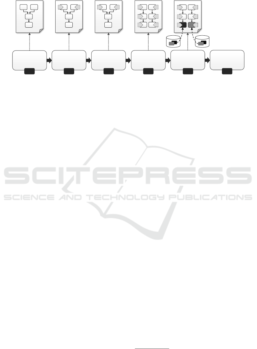
5.2 System Architecture
Winery is a graphical modeling tool for modeling
and managing applications using TOSCA. Figure 5
presents existing components and the newly devel-
HTTP REST API
Winery Backend System Components
Winery UI Components
Application,
Templates, Types &
Plans Database
CSAR Importer
TOSCA
Topology Model Editor
Templates, Types, Plans &
CSARs Management UI
CSAR
Packager
TOSCA Topology
Splitting &
Matching
Cloud Provider
Database
Application, Templates,
Types, Plans Management
Cloud Provider Management
Figure 5: Enriched Winery Architecture.
oped components. The TOSCA Topology Model Edi-
tor is used for modeling application topologies. The
Templates, Types, Plans & CSARs Management UI
offers managing all TOSCA artifacts. Both UI com-
ponents communicate with the backend using a HTTP
REST API. The backend itself is capable of importing
TOSCA artifacts by importing Cloud-Service Archives
(CSARs). The management component offers an in-
terface to access the database and to package CSARs.
Winery stores everything in the Application, Templates,
Types & Plans Database. The CSAR Packager exports
CSARs, which are consumable by the OpenTOSCA
container (Binz et al., 2013).
Winery has been extended to include the splitting
and matching functionality.
2
First of all, a function-
ality to define and manage cloud providers has been
developed. The idea is to store all components of-
fered by each cloud provider using TOSCA-compliant
Node Templates and group the provider repositories
in namespaces. These repositories are stored in the
Cloud Provider Database. The component for model-
ing topologies has been extended to support specifying
target labels at Node Templates. After completing the
model and setting the desired target labels, the user re-
quests a split and match using the split button. This re-
quest is received by the HTTP REST API which in turn
routes the request to the TOSCA Topology Splitting &
Matching component. This component first checks the
validity of the input topology (Algorithm 1). There-
after, the splitting algorithm (Algorithm 2) is executed,
which produces and stores a new Service Template
taking the suffix “-split” in the name. This Service
Template is then used as input for the matching algo-
2
https://github.com/eclipse/winery
CLOSER 2017 - 7th International Conference on Cloud Computing and Services Science
256

rithm (Algorithm 3), which produces and stores a new
separate Service Template taking the suffix “-matched”
in the name. This Service Template can then be ex-
ported using Winery’s CSAR packaging functionality.
That CSAR can then be used in the OpenTOSCA con-
tainer for deployment.
5.3 Evaluation
The automation of the method enables a splitting and
matching without the need for a manual intervention.
Using the presented prototype, the duration of split-
ting and matching topologies with different amount of
components (10, 20, and 30) at different matching lev-
els (IaaS and PaaS) to 3 cloud providers is measured.
Thus, six cases are distinguished.
In the test series, the median based on 10 mea-
surements for each case is calculated. For matching
a topology with 10 components to IaaS providers the
median is
40 ms
(lowest value) and for matching a
topology with 30 components to PaaS providers the
median is
772 ms
(highest value). Thus, we showed
that the required time is significantly reduced by the
automation compared to the manual execution.
6 RELATED WORK
Different approaches dealing with the requirements
of multi-cloud applications exist (Petcu, 2013). Petcu
categorizes requirements by development, deployment,
and execution. The deployment category includes the
selection and the deployment in multiple clouds. Our
approach falls in the deployment category.
The MOCCA method (Leymann et al., 2011) and
the optimal distribution framework presented by An-
drikopoulos et al. (2014a) are examples for approaches
dealing with the optimal cloud distribution. Both ap-
proaches facilitate an optimal distribution of compo-
nents based on a given set of parameters. However,
automated splitting of middleware and infrastructure
components as well as a matching with cloud provider
components is not considered. The optimal distribu-
tion framework determines a distribution based on
topology fragments, which represent cloud offerings
for application-specific components. Components on
a lower level are not considered.
The approach for distributing applications by
Kaviani et al. (2014) is based on code and data parti-
tioning, but matching with cloud providers is not con-
sidered. Architectures for selecting the optimal IaaS
for required VMs are provided by Chaisiri et al. (2009)
and Subramanian and Savarimuthu (2016). Algorithms
for optimal distribution are introduced, but only for a
VM-based deployment at IaaS cloud offerings.
The TOSCA-based approach by Carrasco et al.
(2014) to deploy multi-cloud applications also pro-
vides a TOSCA extension similar to targetLabels: a
location element is added to Node Templates to indi-
cate the target cloud. Again, only application-specific
components are considered.
A topology completion approach by Hirmer et al.
(2014) based on a requirement and capability matching
enables the completion of incomplete TOSCA topolo-
gies. The first step of our matching algorithm is in-
spired by this approach: in case of open requirements
on the lowest level a suitable hostedOn-successor is
determined in a similar way. Arnold et al. (2008) pro-
vide abstract topology fragments as patterns,6 which
can be used to complete target topologies by mapping
virtual components to existing components. A similar
approach are multi-image cloud templates matched to
the source system with potential modifications of the
source system (Pfitzmann and Joukov, 2011). Proper
solutions are mappings with these prepared templates,
a flexible distribution and splitting is not possible.
There are also multi-cloud development ap-
proaches such as Uni4Cloud (Sampaio and Men-
donça, 2011) or MODAClouds (Ardagna et al., 2012).
Uni4Cloud is focused on matching IaaS cloud offer-
ing only, whereas MODAClouds enables a dynamic
matching to all deployment models. The splitting of
whole application stacks in accordance with chosen
cloud providers is not in the focus of these approaches
Both explicitly model applications for multi-cloud en-
vironments and do not treat lower-level components.
7 CONCLUSIONS
In this paper we presented the Split and Match Method
that enables splitting of deployment models based on
a manually specified distribution on the business layer
and the automated deployment of the resulting model.
Therefore, a formalization and algorithms to automate
the method steps were presented. The method eases
the redistribution of application components and, thus,
reflecting strategical decisions on the technical deploy-
ment layer. The approach is validated by a TOSCA-
compliant prototype. Nevertheless, the approach is
not restricted to TOSCA and can be applied to any
graph-based modeling language.
We plan to extend this approach to cope with more
relation types reflecting tight coupling as well as inter-
preting other ways of expressions for tight coupling.
These could be inter alia Quality of Service aspects,
like security or response time constraints.
Topology Splitting and Matching for Multi-Cloud Deployments
257

ACKNOWLEDGEMENTS
This work is partially funded by the BMWi project
SmartOrchestra (01MD16001F).
REFERENCES
Andrikopoulos, V., Gómez Sáez, S., Leymann, F., and Wet-
tinger, J. (2014a). Optimal Distribution of Applications
in the Cloud. In Proceedings of the 26
th
International
Conference on Advanced Information Systems Engi-
neering (CAiSE 2014), pages 75–90. Springer.
Andrikopoulos, V., Reuter, A., Sáez, S. G., and Leymann,
F. (2014b). A GENTL approach for cloud application
topologies. In Service-Oriented and Cloud Computing,
pages 148–159. Springer Nature.
Ardagna, D., Di Nitto, E., Casale, G., Petcu, D., Mohagheghi,
P., Mosser, S., Matthews, P., Gericke, A., Ballagny, C.,
D’Andria, F., et al. (2012). Modaclouds: A model-
driven approach for the design and execution of ap-
plications on multiple clouds. In Proceedings of the
4th International Workshop on Modeling in Software
Engineering (MiSE 2012), pages 50–56. IEEE Press.
Arnold, W., Eilam, T., Kalantar, M., Konstantinou, A. V., and
Totok, A. A. (2008). Automatic Realization of SOA
Deployment Patterns in Distributed Environments. In
Proceedings of the 6
th
International Conference on
Service-Oriented Computing (ICSOC 2008), pages
162–179. Springer.
Binz, T., Breitenbücher, U., Haupt, F., Kopp, O., Leymann,
F., Nowak, A., and Wagner, S. (2013). OpenTOSCA
– A Runtime for TOSCA-based Cloud Applications.
In Proceedings of the 11
th
International Conference
on Service-Oriented Computing (ICSOC 2013), pages
692–695. Springer.
Breitenbücher, U. (2016). Eine musterbasierte Methode zur
Automatisierung des Anwendungsmanagements. Dis-
sertation, Universität Stuttgart, Fakultaet Informatik,
Elektrotechnik und Informationstechnik.
Breitenbücher, U., Binz, T., Kopp, O., Leymann, F., and
Schumm, D. (2012). Vino4TOSCA: A Visual Notation
for Application Topologies based on TOSCA. In On
the Move to Meaningful Internet Systems: OTM 2012
(CoopIS 2012), pages 416–424. Springer.
Breitenbücher, U., Binz, T., Kopp, O., Leymann, F., and
Wettinger, J. (2013). Integrated Cloud Application Pro-
visioning: Interconnecting Service-Centric and Script-
Centric Management Technologies. In On the Move to
Meaningful Internet Systems: OTM 2013 Conferences
(CoopIS 2013), pages 130–148. Springer.
Carrasco, J., Cubo, J., and Pimentel, E. (2014). Towards a
flexible deployment of multi-cloud applications based
on TOSCA and CAMP. In Proceedings of the Third
European Conference on Service-Oriented and Cloud
Computing (ESOCC 2014), pages 278–286. Springer.
Chaisiri, S., Lee, B.-S., and Niyato, D. (2009). Opti-
mal virtual machine placement across multiple cloud
providers. In Proceedings of the 2009 IEEE Asia-
Pacific Services Computing Conference (APSCC 2009),
pages 103–110. IEEE.
Hirmer, P., Breitenbücher, U., Binz, T., Leymann, F., et al.
(2014). Automatic Topology Completion of TOSCA-
based Cloud Applications. In GI-Jahrestagung, volume
P-251 of GI, pages 247–258. GI.
Kaviani, N., Wohlstadter, E., and Lea, R. (2014). Partition-
ing of web applications for hybrid cloud deployment.
Journal of Internet Services and Applications, 5(1):1–
17.
Kopp, O., Binz, T., Breitenbücher, U., and Leymann, F.
(2013). Winery – A Modeling Tool for TOSCA-based
Cloud Applications. In Proceedings of the 11
th
Inter-
national Conference on Service-Oriented Computing
(ICSOC 2013), pages 700–704. Springer.
Leymann, F. (2009). Cloud Computing: The Next Revolu-
tion in IT. In Proceedings of the 52
th
Photogrammetric
Week, pages 3–12. Wichmann Verlag.
Leymann, F., Fehling, C., Mietzner, R., Nowak, A., and
Dustdar, S. (2011). Moving Applications to the Cloud:
An Approach based on Application Model Enrichment.
International Journal of Cooperative Information Sys-
tems, 20(3):307–356.
OASIS (2013a). Topology and Orchestration Specification
for Cloud Applications (TOSCA) Primer Version 1.0.
Organization for the Advancement of Structured Infor-
mation Standards (OASIS).
OASIS (2013b). Topology and Orchestration Specification
for Cloud Applications (TOSCA) Version 1.0. Organi-
zation for the Advancement of Structured Information
Standards (OASIS).
Petcu, D. (2013). Multi-Cloud: expectations and current
approaches. In Proceedings of the 2013 International
Workshop on Multi-Cloud Applications and Federated
Clouds, pages 1–6. ACM.
Pfitzmann, B. and Joukov, N. (2011). Migration to Multi-
Image Cloud Templates. In Proceedings of the IEEE
International Conference on Services Computing (SCC
2011), pages 80–87. IEEE.
Sampaio, A. and Mendonça, N. (2011). Uni4Cloud: An Ap-
proach Based on Open Standards for Deployment and
Management of Multi-cloud Applications. In Proceed-
ings of the 2
nd
International Workshop on Software
Engineering for Cloud Computing (SECLOUD 2011),
pages 15–21. ACM.
Subramanian, T. and Savarimuthu, N. (2016). Application
based brokering algorithm for optimal resource pro-
visioning in multiple heterogeneous clouds. Vietnam
Journal of Computer Science, 3(1):57–70.
Wettinger, J., Binz, T., Breitenbücher, U., Kopp, O., and
Leymann, F. (2014). Streamlining Cloud Management
Automation by Unifying the Invocation of Scripts and
Services Based on TOSCA. International Journal of
Organizational and Collective Intelligence (IJOCI),
4(2):45–63.
CLOSER 2017 - 7th International Conference on Cloud Computing and Services Science
258
