
An Integrated Inspection System for Belt Conveyor Rollers
Advancing in an Enterprise Architecture
Richardson Nascimento
1,3
, Regivaldo Carvalho
1,3
, Saul Delabrida
2
, Andrea G. C. Bianchi
2
,
Ricardo Augusto Rabelo Oliveira
2
and Luis G. Uzeda Garcia
3
1
School of Mines, Federal University of Ouro Preto (UFOP/PROFICAM), Ouro Preto, Brazil
2
Department of Computing (DECOM), UFOP, Ouro Preto, Brazil
3
Instituto Tecnol´ogico Vale (ITV), Ouro Preto, Brazil
Keywords:
EA Integration, Maintenance Planning, Monitoring System, Conveyor Belt Rollers.
Abstract:
One of the most criti cal equipment used by mining companies i s the belt conveyor. Thousands of kilometers
of these elements are used for bulk material transportation. A belt conveyor system is composed of several
components, and the maintenance process is not trivial and usually reactive. Thousands of dollars are lost
per hour with the failure of a conveyor belt system. This occurs due to the lack of appropriate mechanisms
for efficient monitoring and integration of this process to the enterprise systems. This paper presents a novel
monitoring and integration architecture for a Brazilian mining company. The challenge is to provide a mobile
control system and its integration with the current enterprise solutions. We also describe a set of restrictions
for the particular component (rollers) in order to identify methods for the integration. Preliminary r esults
demonstrate our solution is a feasible alternative for the case study.
1 INTRODUCTION
Belt conveyors are the most common m e ans used
to transport bulk material in the mineral industry.
Despite their im portance, there are still significant
challenges to guaranteeing their op eration under re-
asonable and safe conditions. Part of the problem re-
fers to the equipment extent that ranges from a f ew
meters to several kilometers. A sm all num ber of com-
ponen ts is grouped on the head or the tail of the con-
veyor belt system, but most of them are sprea d al-
ong the belt conveyor extension , posing difficulties
to their monitor ing an d serv ic ing. One of the com-
ponen ts that requires particular attention is the rol-
ler. A small conveyor belt of 150 meters has nearly
450 carryin g rollers and 50 return rollers. Curre ntly,
the company has no solution to remotely evaluate the
condition of a roller and trig ger adequate actions on
enterprise systems, such as opening work orders o r
requesting the purchase of n ew rollers, so inspectors
manually input all the data resulting from inspecti-
ons on such systems. This lack of integration leads
to a wide range of problems, which vary from low-
consequence typing errors to serious situatio ns, where
a defective roller is no t replaced and may result in a
belt catching fire. Therefore, the condition monito-
ring solution needs to be seamlessly integrated with
enterprise systems. In this context, this paper reviews
some of the available solutions to monitoring the sta-
tus of rollers in conveyor belt systems a nd proposes an
architecture to addre ss the main requirements related
to the integration of such solutions with enterprise sy-
stems used in the company. A Data Cap turing Layer
is proposed with the use of an Unmanned Aerial Vehi-
cle (UAV) carrying different sensors to obtain condi-
tion data from the rollers. On-field preliminary tests
demonstra te that the utilization of the UAV is feasible,
as it can quickly get h igh-resolu tion images from se-
veral c ompon ents; thus, reducing inspectio n time and
increasing safety. Therefore, the main contributions
of this paper are:
• A review of the main techniques to monitor the
status of rollers and a discussion about some of
the solutions
• An architecture to integrate the condition monito-
ring of rollers to enterprise systems
This paper is structured as follows: Section 2 sta-
tes the main difficulties to monitor the condition of
rollers and the conseque nces of the lack of integra-
190
Nascimento, R., Carvalho, R., Delabrida, S., Bianchi, A., Oliveira, R. and Garcia, L.
An Integrated Inspection System for Belt Conveyor Rollers - Advancing in an Enterprise Architecture.
DOI: 10.5220/0006369101900200
In Proceedings of the 19th International Conference on Enterprise Information Systems (ICEIS 2017) - Volume 2, pages 190-200
ISBN: 978-989-758-248-6
Copyright © 2017 by SCITEPRESS – Science and Technology Publications, Lda. All rights reserved
tion with enterprise systems. Section 3 describes key
aspects of the rollers status monitoring scheme and
discusses so me of the solutions and their applicability
as the Data Capturing layer of the integrated archi-
tecture. Sec tion 4 presents the main requir e ments of
related companies in the area and proposes a system
architecture to address them. Sectio n 5 reviews the
concept of Enterprise Service Bus (ESB) and its role
as a key component to integrate c ondition monitoring
with enterprise systems. Section 6 describes the on-
field te sts performed with the UAV and related senso rs
to confirm the feasibility of the Data Capturing lay er.
2 PROBLEM STATEMENT
Assets monitorin g can follow two different strate-
gies. One of the mode ls currently in use is based
on the type of inspection, in which tasks are split
into several teams, such as mechanical, ele ctrical,
and hydraulic. Each team walks through the en tire
port and assess equipment conditions without using
instruments. After that, they register the data in
the Compute rized Maintenance Management System
(CMMS) requesting to repair or replace the faulty
components through a Work Order (WO). This sen-
sory and subjective proced ure is known as sensitive
inspection. This type of inspection uses tacit kn o-
wledge of the operators to identify problems on the
components. Another approach is the so-called pre-
dictive inspection, in which tea ms use instruments to
collect data from vibration , noise, and temperature for
subsequen t analysis in a specialist software. If neces-
sary, a WO is manually cr eated in the CMMS.
Regardless of the inspection type, the lack of inte-
gration b e tween the collected da ta , the specialist sy-
stems and the CMMS presents several problems for
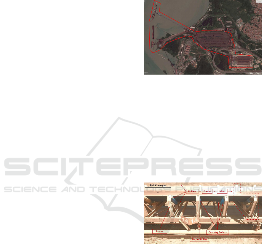
the compa ny. This is particularly critical in hetero-
geneous environments, such as th e Maritime Termi-
nal of Ponta da Madeira (TMPM), located in the S˜ao
Lu´ıs, the ca pital of Mara nh˜ao State. The po rt is the
end point of the logistical system that transports the
iron ore extracted in the Caraj´as mining complex to
load sh ips bound for Asia and Europe. This is the
biggest port for the export o f Brazilian iron ore and
one of the largest in the world (ANTAQ - Agˆencia
Nacional de Transporte Aquavi´arios, 2015). The fo-
recast is to embark 170 million tons (Mt) in 2017,
which pushes its extensive and complex infrastructure
to the limit. This infrastructure is composed by: 8
ship loader s, 8 car dumpers, 7 reclaimers, 5 stackers,
4 stacker-reclaimers, and 149 belt conveyor lines, to-
taling 120 kilometers of conveyor belts and arou nd
200,000 rollers, scattered on approximately 500 hec-
tares. Figure 1 shows the entire port area, which is
bounded by the red polygon .
Figure 1: Maritime Terminal of Ponta da Madeira (TMPM).
Captured from Google Earth.
Although it is not complex equ ipment, the belt
conveyor lines are the p rimary asset of the port since
stopping o ne of them impacts an entire embark route.
The rollers are the most numerous and critical compo-
nents, whose function is to support the conveyor belt
and the material it carries, as well to receive the im-
pact of material that is transferred between belt c on-
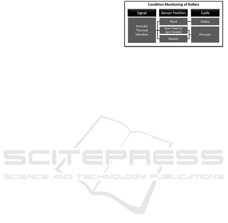
veyors and the transfer points (i.e. chutes). Taking
into consideration the enormous quantity of rollers in
the mining industry, monitoring their condition beco-
mes a significant challenge. Figure 2 shows some of
critical points to be monitored, includ ing rollers.
Figure 2: Section of a belt conveyor line.
Rollers suffer from severe wear and demands a
higher frequency of inspection. Usually, the TMPM
only uses sensitive inspection, where each one of the
rollers installed in the conveyor belts is ch ecked visu-
ally. Given that it is impossible to view the rollers on
the other side of the belt, both conveyor sides should
be covered. Given the large n umber o f rollers, the use
of a predic tive instrument to collect thermal, a c oustic,
or vibration data becomes pr ohibitive because of the
time it would take to collect such information manu-
ally for each roller. An other problem caused by the
lack of integration between the specia list systems of
instruments and the CMMS is the time required to
create a manual WO for each roller. Without externa l
An Integrated Inspection System for Belt Conveyor Rollers - Advancing in an Enterprise Architecture
191

tools to measure data, defect location depends on in-
spector experience. Furthermore, the unc ertainty may
lead to the replacement of all three roller s of an idler,
resulting in unnecessary costs to the co mpany.
Given that the port’s resources and capacity to
execute maintenance are limited, prior planning of all
requested services must be carried out with mastery.
The Maintenance Planning and Control (MPC) is re-
sponsible for prioritizing the WO from different in-
spection groups and regular maintenance plans. Due
to a predominance of subjective criteria over several
sources of in formation, it is difficult to define clear
policies for resource allocation, including human re-
sources. Therefore, the meetings with all stakehol-
ders to d etermine the prioritization may not a lways
achieve the b e st results since prioritization is defined
by the persuasive power of the participa nts and not by
technical aspects. The consequence is that if a critical
task is not prioritized , the probability of equipment
breakd own dramatically increases and may cause un-
desired operatio nal shutdown resulting in a dditional
costs and production loss.
A remarkable occurrence of a critical case was the
fire that occurred in the belt conveyor TR-315K-36.
Rollers were da maged and there was the loss of 300
meters of belt, as well as d amage to all the electri-
cal and automation systems. The fire was caused by
a broken bearing of a roller of the catenary table. Fi-
gure 3 shows the damage caused by a maintenance
failure. In this case, a n inspection was performed a
few days earlier, but the problem was not identified or
the roller was not damaged at the time of in spection.
A higher inspection frequency could have detec te d the
problem, but due the large amount of equipment, and
the limited human resources available its impossible
to increase visiting frequency with the current in-
spection methods.
Figure 3: Fire on belt conveyor system TR-315K-36.
The fire of the TR-315K-36 was not an unfortu -
nate coincidence, but a recurring problem w hose con-
sequence of the damage can be catastrophic. Data
extracted from company’s internal systems show that
between 2014 and 2016, only in the ports of Ponta
da Madeira (Norther n System) and Tubar˜ao (So uthe-
ast System), there was more than R$ 2.7 million in
material losses due to fires caused by rollers failures,
accounting for 600 hours of operational stops.
The o c currence of a high number of undesirable
breaks can lead to a vicious cycle, since any unex-
pected breakdown causes the cancellation of a pre-
ventive service to attend the emergency service, and
failure to perform preventive tasks can generate fur t-
her breaks. Furthermore, it elevates the maintenance
cost and operating losses, as well as the exposure of
employees to risk.
Even with an autom a te d and assertive inspection
system, but without a robust integration between col-
lected data and enterprise systems leads the company
to face the same management and plannin g problems
previously mentioned. On the other hand, an auto-
mated inspection process integrated with such sys-
tems will contribute to a greater assertiveness in the
diagnosis of the failures, a llowing gre a te r inspec tion
frequency of the assets, and finally technical prioriti-
zation criteria to be used by the PCM. Such impro-
vements can contribute to new levels of equipment
reliability, reducing maintenance costs and increasing
production.
Considering that the belt conveyor rollers are the
most numerous components of the TMPM and they
present the bigge st challenges in its inspection, this
paper prop oses an architecture to address the pro-
blems related to the rollers’ data ac quisition and the
integration flow to enterprise systems.
3 BACKGROUND
This section presents the techn iques to monitor the
condition of rollers and some of the available soluti-
ons, discussing wh e ther they can be adopted or not
regarding the data capturing layer on the study case.
3.1 Techniques for Rollers Condition
Monitoring
Before introducing the techniques to monitor the con-
dition of a roller, it is important to present a brief
explanation of its parts. A roller is composed of an
outer cylindrical surface (cladding) with a pair of be-
arings (left and right) mounted on a stationary shaft
(Reicks, 2008). With such stru cture, three prim a ry
defects can affect a roller: breaking, overheating, and
ICEIS 2017 - 19th International Conference on Enterprise Information Systems
192
locking. While the latter affects only the bearings and
can lead to overheating, remaining failures affect both
the be a rings and the cla dding (Xiao-ping Jiang and
Guan-qiang Cao, 2015).
Since most o f the failures originate on the be-
arings, the rollers’ condition monitoring techniques
must be primarily capable of assessing their state. Li-
terature highlig hts three main monitoring methods ac-
cording to the signal used: a coustic (Xiao-ping Ji-
ang and Guan-qiang Cao, 2015), vib ration (Tan et al.,
2015) a nd thermal(Yang, 2014). Both acoustic and vi-
bration analysis rely on the principle detailed by (Gi-
rdhar and Scheffer, 2004 ) where freque ncies emitted
by the bearing depend on its construction chara c te -
ristics and faulty behaviors can be detected by unex-
pected freque ncies with specific signatures. In brief,
such techniques consist of signal capturing, treatment,
and the extraction of features that indicate current de-
fects or future failures. On the other han d, thermal
monitoring consists of obtaining the temperature of
the bearing at a specific in stant, given tha t tempera-
tures above a clear-cut threshold indicate that the id-
ler roll has to be replaced immediately. An important
consideration is that vibration and acou stic monito -
ring can detect failures at an early stage whereas ther-
mal monitoring is reactive, as tem perature r ises only
occur when the defect is already in a critical phase and
there is little reaction time (Hawksworth et al., 20 03).
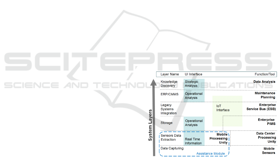
This behavior refers to the discussion of o nline
monitoring versus periodic inspections, which are
performed in cycles defined by assets criticality and
the availability of resources (human, tools, sensors).
Sensor position and installation characteristics, such
as fixed, semi-fixed/semi-mobile or mobile (Liu et al.,
2014) change the monitoring cycle a nd are decisive
in categorizing the system as online or periodic, as
demonstra te d in Figure 4. Fixed sensor s are conti-
nuously monitoring the system (online) while mobile
sensors (o r semi-fixed) can monitor the system only
during the periodic inspection. Although online mo-
nitoring is preferable in most situ a tions, their adop-
tion for belt conveyor systems poses significant is-
sues that cannot be overlooked, particularly becau se
of the following restrictions: a) the ability to obtain
data from multip le components without yielding add i-
tional maintenance, and b) the installation and main-
tenance costs c annot be proportional to the number of
monitored components.
This stu dy describes the background technologies
for the development of a solution integrated into the
architecture proposed in the Sectio n 4. This section
represents a guide to define the techno logies able to
provide the final settlement for the Data Capturing
layer.
Figure 4: Diagram of the condition monitoring of rollers.
3.2 Available Solutions for Assessing a
Rollers’ Condition
One of the main discussed r estrictions is th e sensors
installation and main tenance costs that can be prohibi-
tive due to the huge volume present at the port of this
study case, which is close to 200,00 0 rollers. In this
scenario, the a doption of fixed sensors must be ca-
refully appraised. Nevertheless, in 20 07, (Lodewijks
et al., 2007) proposed the concept of a ”smart idler”,
an Io T solution that consists of a roller embedded with
an electronic circuit containing a batter y power sup-
ply, a RFID identification tag, a temperature sensor,
and a radio for data transmission. As a prototype on
early development stages, the author recog nizes that
the costs are forbidding (around 40% to 50% of th e
roller value) and requires battery replacement.
To ad dress some of these issues, (Pang and Lode-
wijks, 2011) presents an evolution, w here each roller
(with sensors) ha s an energy harvesting system and
roller-to-roller communication using self-healing net-
works. This strategy reduces the number of commu-
nication gateways and improves system’s reliability.
The autho rs do not detail the costs, but the incorpo-
ration of an energy harvesting system is prone to in-
crease acquisition price and to reduce sustaining c osts
since the battery is no longer requ ired. Some manu-
facturers, such as (Ing enuity, 2016; Vayero n Pty Ltd,
2016) already market similar technologies. The main
handicap is the requirement to replace each roller of
a conveyor system with a Smart m odel to obtain on-
line monitoring ; if a sin gle ro ller is not replaced, the
whole system is imp aired. Conceded that the average
lifetime of a roller is around 3 to 4 ye ars, new p ro-
jects ar e more likely to ad opt such technology since
it is hard to support scrapping the existing rollers to
install Smart ones.
Another approach using fixed sensors, but which
aims to reduce the number of sensing elements, is de-
tailed by (Li et al., 20 13). The au thors p ropose to
install a limited number of accelerometers on the ou-
ter structure of the belt conveyor system to obtain the
vibration data of multiple rollers. They used Wavelet
An Integrated Inspection System for Belt Conveyor Rollers - Advancing in an Enterprise Architecture
193

Packet Decomposition (WPD) (Coifman a nd Wicker-
hauser, 1992 ) to decompose the vibration signals and
determine the energy of each ban d as the feature of in-
terest. Finally, they adopted Support Vector Machine
(SVM) (Cortes and Vapnik, 1995) to cla ssify faulty
signals in different failure modes. The approach is
promising, but they had to install one sensor for each
three frames, corresponding to a distance of approxi-
mately 6 meters; what still means a significant num-
ber o f sensors since some of the belt conveyor systems
can extend th e mselves fo r kilometers.
Still discussing fixed sensors, (Hu et al., 2011)
performed tests in an underground coal mine of a rol-
ler’s temperature monitoring system based on optical
fiber. The Distributed Optical Fiber Sensor (DOFS)
uses optical fibe r both as sensing and transmission
media for roller temperature; an interesting appro-
ach to reducing the total number of sensing elements.
The system is ca pable of self-diagnosis, detecting sig-
nal degradatio n and fiber disruption; another positive
characteristic du e to the ha rsh environment where it
is used and th e possibility of accidental damage du -
ring maintenance activities. (Yang, 2014) c onducted
a series of trials on a similar system and concluded
that the technology is indeed su itable to perform con-
dition monitoring on rollers, but requires a detailed
analysis to defin e optical cable positioning in order to
enhance temperature detection a nd insulate environ-
mental influence (humidity, ambient temperature va-
riance, ventilation, dust, etc.) from the results. This
can pose a challenge to operations because of the di-
versity of belt conveyor systems and conditions found
on mining operations, even though some c ommercial
solutions w ith this technology are already available
(AP Sensing, 2017; Yokogawa, 2017).
(Yang et al., 2 016) describes an intermediate solu-
tion b etween fixed and mobile sensing. Th e authors
developed a mobile robot that uses the existing struc-
ture of a belt conveyor system to perform inspections
using infrared thermography of different components
(rollers, pulleys, and mo tors). An inspection track
is attached to both sides of the belt conveyor frame
and vertically positioned between the carrying idlers
and lower b elt. The robot has an infrared camera
and employs the gear-and-rack method to move along
the track while con tinuously capturing images, which
are processed with a combination of pattern recogni-
tion algorithms to identify components of interest and
temperature. The use of the belt conveyor system’s
own structure can simultaneously be seen as the met-
hod’s main advantage and disadvantage. While long
belt conveyor systems can benefit from having a con-
tinuous monitoring system as proposed, it may not
be economical to install one on all conveyor systems,
particularly the short ones. It is reasonable to employ
maintenan ce efforts to inspect and maintain a robot
that can autonomously monitor a 900-meter conveyor
system, but it is not feasible to d o the same for a 20-
meter belt conveyor line. Regardless of the extension,
the existing belt conveyor systems can also present
challenges regarding the required adaptions to instal-
ling the robot as proposed .
An alternative to installing sensors on each belt
conveyor system is the use of mobile sensors. In this
direction, the pe riodic inspections that mainte nance
personn el performs today can illustrate this method
as long as they use adequate tools to collect acou-
stic, therm al, or vibration signals. Due to the risks,
inefficiency, and other drawbacks alread y explained,
it is preferable to adopt an inspection method that mi-
nimizes the need for humans on the field. Thereby,
the patent requested by (Yong et al., 2014) claims
the use of a multi-rotor UAV (i.e. d rone) to carry
out in spection missions. The m ain innovation is the
autonomous navigation system, which uses reflective
adhesives installed on the belt conveyor system and
other structu res to obtain the vertical and horizontal
orientation of the route and the a ctions to be perfor-
med at each point. The UAV is equipped with a high-
resolution camera for navigation, an infrared camera
for inspection, a RFID reader, and gas concen tration
sensors for the use in coal underground mines, where
methane can cause explosions. It also sends captured
data to ba se stations, wh ic h can perform signal pro-
cessing and retransmission. A similar solution is clai-
med by (ABB Technology AG, 2014), which propo-
ses the employment of ground-eng a ging vehicles and
cable drones for carryin g the sensor structure besides
UAV’s.
The main ad vantage of these proposals when com-
pared to the work of (Yang et al., 2016) is that the
vehicle, aerial or not, can be used to insp ect multiple
belt conveyor systems in an industrial plant since they
are not tied to one of them. On the other hand, an im-
portant q uestion that a rises is the limited battery au-
tonomy, particularly with the adoption of UAV’s. The
fact that the vehicles have to carry a sensor structure
and transmit data significantly contributes to the pro-
blem. Such limitation can be mitig a te d by the use of
battery repla cements and rec harge stations, as discus-
sed in (Suzuki et al., 2012) and (Michini et al., 201 1).
Finally, althou gh online monitoring methods are
preferable, employing them on belt conveyor systems
is not trivial. Even techniques that do not require in -
stalling individual sensors demands adjustments and
individual assessment for each system to be monito -
red. Thus, we und e rstand that mobile sensing using
UAV’s is the best alternative to carrying out the tran-
ICEIS 2017 - 19th International Conference on Enterprise Information Systems
194
sition between status quo with a full dependence of
humans to p erform inspections at a whole new level
where rou tine inspection is automated. Moreover, the
proposed a rchitecture plans to deliver seamless com-
munication between the data capturing layer and other
systems in the organization, which seeks to address
several of the problems caused by the lack of inte-
gration. This can compensate some of the benefits of
online monito ring, while the company prepares itself
to adopt fully monitored systems using fixed sensors.
The next section describes in mor e detail the require-
ments and the proposed architecture to address them.
4 PROPOSED SOLUTION
This section describes current enterprise requirements
for belt c onveyor inspection systems and proposes a
new integration architecture between the new moni-
toring and existent enterprise systems.
4.1 System Requirements
System requirements were discussed together with
the technical staff of the enterprise, while some of the
authors have met the staff on site. Although techni-
cians report several kinds of problems relate d to the
belt conveyor system, roller monitoring was defined
as the priority and focus o f this paper. Due to this
fact, Section 3 presents an evaluation of the kind of
problems and the state-of-the-art solutions p roposed.
This assessment was necessary for the desig n of the
integrated architecture.
A second req uirement of the c ompany is to reduce
the need for human interferenc e a nd presence in the
belt conveyor system while obtainin g technological
platforms for remote monitoring. This fact signifi-
cantly reduces human risks.
Static sensors are not a choice to be considered al-
ong with the b elt conveyor system. T his approach in-
creases the demand for maintenance. For instance, if
cameras are placed on the belt conveyor system, they
should require periodic maintenance, as do the rollers.
In this case, the use of mobile sensors should be the
better solution.
Mobile Robots and Unmanned Aerial Vehicles
(UAV’s, i.e., drones) are alter natives for the monito-
ring system. On the other hand, these d evices bring
the challenge to integrate them with the enterprise sy-
stems. At the same time, a friendly user interface is
necessary fo r the specialist technicians to evaluate the
need of roller maintenance during remo te assessments
and to give support for the m on the inspection. The
board requested a software inter face that provides the
informa tion for the user in real time through an algo-
rithm that is able to make the analysis based on data
captured from the sensors. This module was name d
as Assistance Module (AM).
The next section presents the system architecture
as a proposal to solving the problem. The structure is
shown in layers and represents the integration of all
the monitoring process from the sensor equipment to
the strategic analysis. Although this paper focused on
the rollers, since they are the main assets of the port,
the architecture here proposed is generic and can be
adapted to address other industrial problems, such as
the inspection of transmission lines, wagons, confined
spaces, and others.
4.2 System Architecture
Figure 5 shows th e propo sed architecture for an in-
tegrated monitoring system. All layers have a user
interface except the Data Capturing and Legacy Sy-
stem Integration layer. The user interface appears af-
ter processing the data collected by the sen sors on the
Sensors Data Extraction layer. The shaded area in
the Figure 5 represents the user interface level. The
dashed area represents the IoT components presented
on the architectu re. Both components are discussed in
the Section 4.3. Afterward, each layer and the co m-
ponen ts are described.
Figure 5: System Architecture.
Data Capturing: This layer represents the sen sors
used to ca pture data on the belt conveyor system. A
mobile sensor for monitoring should be utilized as
described in the system req uirements. We should use
many kinds of sensor s, according to what is shown
in the Section 3 when connecting to a robot and a
drone. For in stance, a drone c an use a cam e ra as a
sensor providing images or streaming videos for the
manual/au tomatic analysis. Besides, the video stream
should be processed in order to identify and notify
some anomaly to the operator. This procedure is exe-
cuted by the next layer and is described below.
An Integrated Inspection System for Belt Conveyor Rollers - Advancing in an Enterprise Architecture
195

Sensors Data Extraction: processes the raw d a ta
captured on the previous layer. We define two
subclasses of pr ocessing unity on this layer: Mobile
Processing Unit, and Data Center Processing Unit.
The mobile proce ssing unit represents em bedded har-
dware with power computing capability connected to
the robots or UAVs. This component is necessary
due to the use of mobile platfor ms, and the raw data
collected by sen sors should be processed into MPU.
For instance, the stream obtained from a microphone
can be processed, and an unusual noise tha t repre-
sents a roller’s anomaly can be detected; then, an
event should be generated. The environment moni-
tored can have no con ditions for providing the con-
nection among the sensors and information techno-
logy (IT) infrastructure. The absence of this compo-
nent makes the assistance module an unfeasible al-
ternative. Algorithms unable to be executed on em -
bedded platforms have to be performed in data center
processing units. In this case, the data collected from
the sensors are stored in the secondary memory of the
mobile platform an d transferred wh en the mobile p la t-
form has a connection available.
Storage: This is the first layer of the architecture
that demands integration with third-party systems.
The process information management system or plant
informa tion management system (PIMS) is a histo-
rical database that receives data from several sour-
ces. In a second phase, this data is used for the
production of statistical information provided by the
PIMS functionalities. The current version stores data
from many different in dustrial components an d the
data collecte d from the mobile sensors should also be
stored into PIMS. This way, the engineers and techni-
cians can make an operational analysis about the sta-
tus of the belt conveyor system.
Legacy Systems Integration: The current systems
available in the company can re c eive data from legacy
systems using the concept of Service-Oriented Archi-
tecture (SOA). Several services are alre a dy available
on the Enterprise Service Bus (ESB) via API’s, web
services, message queues, etc. They can receive data
from bottom layers and provide it to enter prise sys-
tems, and can send information from such systems to
the layers below. Due to this feature , a Sensor Data
Extraction layer can release sensor data to these sys-
tems without creating additional services. This layer
is essential for the integration of the new components
of the monitoring system a nd the other systems avai-
lable in the company. Due to this fact, the Section 5
provides more details of th is layer.
ERP/CMMS: Layer of the integrated system used
for main te nance planning. The main bottleneck of the
current practice in the company is to rece ive data from
the systems contained in the previously mentioned
layers. In some cases, there are no sensors to iden-
tify maintenance deman ds and the process is wholly
dependent of human verification. Currently, the com-
pany uses the SAP Plant Maintenance (SAP-PM) as
its CMMS system, which is part of the SAP ERP. No
further details can be discussed about the ERP and ot-
her systems due to company r estrictions.
Knowledge Discovery: This is an additional layer
compare d with the current version of the co mpany’s
enterprise system. This new layer uses da ta mining
and mach ine learning algorithms in order to identify
and extract new features and knowledge. Such re-
sults can be used in expert systems or modules at the
ERP/CMMS layer for ope rational analysis, making
decision-making smarter and more autonom ous.
4.3 User Interface and IoT Components
Besides the services that each layer provides, they
may interact with User Interface ser vices and IoT In-
terface services. This section describes these relati-
onships.
User Interface: Users can re c eive information
about the mainten ance status in distinct granularity.
This means that the architecture p rovides different le-
vels of analysis. Real Time Inform ation represents the
informa tion retrieved for the user while a conveyor
belt line is on inspection . Operational An a lysis pro-
vides information about the status of the compon ents
from a short p eriod of observation, and Strategic Ana-
lysis is information retrieved for the user related to
the long-term maintenance planning as well as new
informa tion generated by the use of data-min ing al-
gorithms.
All layers, except Data Capturing and Legacy Sy-
stems Integration, include a User Interface. Table 1
summarizes the relationship between each layer, the
type of hu man analysis, and a user inte rface example.
IoT Interface: Some components of the belt con-
veyor system have machine-to-machine communica-
tion and can perform an IoT application, such as the
smart-idlers, discussed on Section 3. Although it is
not the focus of this paper to incorporate these ele-
ments, they are represented in the architecture pro-
posed for further integration. Relevant information
ICEIS 2017 - 19th International Conference on Enterprise Information Systems
196
should be delivered to the users, considering the ag-
gregation of the data collected fr om IoT components
and th e monitored rollers.
5 SYSTEMS INTEGRATION
As discu ssed on Section 2, a central contr ibutor to
the existing problems is the lack of effective integra-
tion between inspections and enterprise systems, thus
impairing the information flow from different sour-
ces and jeop a rdizing maintenance planning, procure-
ment, and other processes. The company already has
in place an Enterp rise Service Bus (ESB) with diffe-
rent services that can be used to seamlessly integrate
the Sensor Data Extraction layer (at this moment, re-
ferred to as SDE) with corporate systems. The reuse
of existing services on the ESB brings several be ne-
fits to the company: (i) the deployment of new tools is
faster and cheaper, considering that most of the inte-
gration capabilities can be delivered without creating
additional services and (ii) also facilitates commu ni-
cation with the use of adapters for different standards
and protocols.
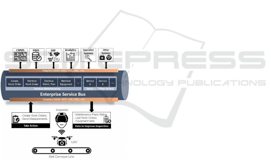
Figure 6: U se of an ESB to integrate inspection to enterprise
systems.
Figure 6 presents a practical example of how the
proposed architecture takes a dvantage of the exis-
ting ESB. Some of the available services expose the
CMMS data, such as work orders, maintenance plans,
and master data of equipment. As the UAV inspects
the belt conveyor system, the SDE can use a combi-
nation of these serv ic es to display information to the
inspector, such as the status of the latest work order
created for the inspected roller combined with man u-
facturer information and the component’s installation
date. As the CMMS also exposes services that allow
external systems to manipulate its entities securely,
the SDE can send the current temperature of a rol-
ler and allow the inspector to create work orders right
from the user interface as soon as it detects a failure.
This set of possibilities reduc es rework an d give main-
tenance plan ners a view of the situation right from
the inspection, addressing most of the gaps d iscus-
sed. Such benefits are n ot restricted to the CMMS
system and maintenance processes. The integration
with environmental monitoring systems ca n display
live information of weathe r forecasts, wind speed and
direction, aiding in UAV teleoper a tion avoiding pos-
sibly dangerous situations.
Finally, all the raw data captured during the in-
spection can be stored on PIMS using its services. La-
ter, specialists, along w ith a nalytics systems, can r ead
and analyze inspection results from PI MS. This redu-
ces the effort to deliver the architecture of Section 4,
as such systems also use the ESB to communicate
among them with several services alr eady available.
6 PRELIMINARY EVALUATION
In order to improve awareness of the difficulties fa-
ced by the inspector on the field and to confirm the
feasibility of the proposed Data Capturing Layer of
the architecture, some preliminary tests were execu-
ted. The equipment used to perform the evaluations
was composed of DJI 3 Professional UAV, equipped
with a full- HD camera mounted on a gimbal stabili-
zer, an UltraProbe 10000 for audio acquisition, and
an FLIR i5 th ermogra phic camera. As a preliminary
evaluation, each eq uipment was tested independently.
The integration of all components, data transmission
and integration with enterprise systems are not the fo-
cus of these specific tests an d they are planned as sub -
sequent steps of the project.
A c ertified an d experienced operator piloted the
UAV, keeping a constant altitud e while positioning the
UAV parallel to the belt conveyor line (BCL) and fo-
cusing the full-HD camera to obtain lateral images
of the BCL that contain central and lateral rollers.
Despite the wind, the oper a tor was able to make the
UAV follow the desired route, capturing high-quality
images o f the belt, the roller s (both central and late-
ral), and th e complete lateral structure of the BCL. A
second flight obtained images of carrying and return
rollers. The simple execution of this test demonstrates
an imp rovement on operator safety as th e simulated
inspection was performed from a fixed pilot location,
eliminating risks related to incidents with venomous
animals and drops. Besides, the total time spent to si-
An Integrated Inspection System for Belt Conveyor Rollers - Advancing in an Enterprise Architecture
197
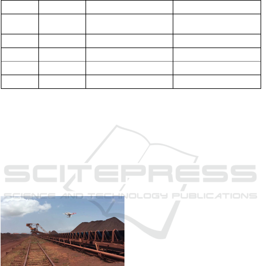
Table 1: User Interaction by layer.
Layer
Type of
Analysis
Description Interface Example
Sensors Data
Extraction
Real time/Online
data
Provided by embedded algorithms
Head Mo unted Displays, tablets,
smartphones with virtual reality
and augmented reality capabilities.
Storage
Operationa l
Analysis
Statistics information from PIMS Reports and graphics
ERP/CMMS
Operationa l
Analysis
Statistics information from
ERP/CMMS
Reports and graphics
Knowledge
Discovery
Strategic
Analysis
Resulting inf ormation data mining
and machine learning algorithms
Reports and graphics
User
Application
Strategic
Analysis
Use of the new information for
creation new expert systems
Experts systems
mulate the inspection was 3min 40s, with 456 rollers
filmed. Comparatively, an average walking along the
BCL at a walking speed of 1. 4m/s plus two second s
to assess each ro ller would take 17min 54s (Long and
Srinivasan, 2013). During the simulated inspection,
the pilot was not flying at full speed and made several
stops, but the quality of images obtained shows that
no stop is required and the UAV could fly at a hig her
speed, red ucing even more the inspection time . Ta-
king into account that the flight was over 228 m and
the maximum speed is 16 m/s, the UAV used can co-
ver this distance in only 14.25 s. Figure 7 shows the
UAV per forming the flight besides a belt conveyor on
a r eal production environment.
Figure 7: Simulated inspection with an UAV over a real
production environment.
The second test obtained audio signals from eight
lateral rollers. The average setup and recording time
using the Ultr aProbe 10000 for eac h roller was 20 se-
conds. During the tests, an e arly-stage defect on the
bearing of on e of the rollers was identified - so an
additional time of 4 0 seconds was spent to confirm
which roller was originating th e signal. The defect
identification depends on the experience of the in-
spector who needs to concentrate on the aud io repro-
duced by the headset. The instrument has an alarm,
but this does not reduce the required attention while
listening to the audio.
Finally, a thermal shooting was performed. The
thermographic camera allows to assess multiple rol-
lers at once, but the inspector needs some time to
identify the hottest p oint of the image and its tempe -
rature. Since the tests were perfo rmed on a hot day,
sometimes the came ra identified the soil in the back -
ground of the BCL as the hottest point. This is an
additional p roblem because sometimes the soil tem-
perature mixed with the bearing temperature, and the
inspector took lo nger to confirm roller failure. For sa-
fety rea sons, to avoid stumbles and drops, the inspec-
tor needed to stop on each id le r to evaluate the imag e,
which increased the total time required fo r inspection.
According to the results of the individual evalua-
tion o f the sensors and the UAV, the Data Capturing
layer of the proposed architecture is feasible regar-
ding equipment. The merging of individual sensors
with the UAV, the adoption of algorithms to aid the in-
spection, and the integration with enterprise systems
will bring more accurate defects de te c tion, reduce re-
work, and improve the maintenance pla nning routine.
7 CONCLUSION
This paper presented several cha llenges related to the
data acquisition of rollers installed on belt conveyors
and how the lack of integration of such information
with enter prise systems a ffects the ma nagemen t and
maintenan ce activities. We proposed a mobile data-
capturing layer with the use of a UAV with embed-
ded sensors that seeks to bring more accuracy in de-
fects detection and reduce manual steps in the main te -
nance processes. We also proposed an Enterprise Ar-
chitecture to integrate the condition monitoring with
existing enterprise system s, improving the on-field in-
spection and providing a holistic view of all belt con-
ICEIS 2017 - 19th International Conference on Enterprise Information Systems
198

veyors present in the port of the study case. A set of
preliminar y on-field tests to evaluate individual equip-
ment d emonstrated that the feasibility of the mobile
data cap turing unity has promising results regarding
inspection time and assertiveness. Although, to em-
bed sensors in the UAV, to develop algorithms to pro-
cess and present data to inspectors are still challenges
to overco me. Therefore, futu re work will concentrate
on the following:
(i) Embed different sensors in the UAV and perform
on-field testing to validate data acquisition
(ii) Create and e mbed algorithms in the UAV to ef-
ficiently d etect defects on rollers, integrating the
outputs with the user interface to improve in-
spection
(iii) Evaluate power consumption of UAV and sen-
sors, developing solutions to improve battery au-
tonomy
(iv) Develop API’s on the ESB to integrate the mo-
bile data capturing unity with enterprise systems
(v) Develop semi-autonomous and fully autonomous
navigation algorithms in the UAV
ACKNOWLEDGMENTS
The authors would like to thank the Federal Univer-
sity of Ouro Preto, Instituto Tecnol´ogico Vale, Vale
S.A., CNPq, Capes and FAPEMI G for support and
providing fun ding for the development of this work.
REFERENCES
ABB Technology AG (2014). Conveyor I nspection With
Unmanned Vehicle Carying Sensor Structure.
ANTAQ - Agˆencia Nacional de Transporte Aquavi´arios
(2015). Estat´ıstico Aquavi´ario da ANTAQ.
AP Sensing (2017). AP Sensing - Fire Detection.
https://www.apsensing.com/application/fire-
detection/. Last accessed on January 11, 2017.
Coifman, R. R. and Wickerhauser, M. V. (1992). Entropy-
based algorithms for best basis selection. IEEE Tran-
sactions on Information Theory, 38(2):713–718.
Cortes, C. and Vapnik, V. (1995). Support-vector networks.
Machine Learning, 20(3):273–297.
Girdhar, P. and Scheffer, C. (2004). 5 – Machinery fault di-
agnosis using vibration analysis. In Practical Machi-
nery Vibration Analysis and Predictive Maintenance,
chapter 5, pages 89–133. Newnes, Oxford.
Hawksworth, S. J., Gummer, J., Davidson, J., and Williams,
M. (2003). Ignition from conveyor idler rollers. In
Proceedings 30th International Conference of Safety
in Mines Research Institutes, pages 461–470, Johan-
nesburg.
Hu, C., Wang, J., Zhang, Z., Yu, X., Gong, H., and Jin,
S. (2011). Applications S tudy of Distributed Optical
Fiber Sensor System in Coal Mine. 2011 Symposium
on Photonics and Optoelectronics (SOPO), (6):1–4.
Ingenuity (2016). Smart-Idler
TM
. http://www.ingenuity-
design.com.au/portfolio-posts/smart-idler/. Last
accessed on January 13, 2017.
Li, W., Wang, Z., Zhu, Z., Zhou, G., and Chen, G. (2013).
Design of online monitoring and fault diagnosis sy-
stem for belt conveyors based on wavelet packet de-
composition and support vector machine. Advances
in Mechanical Engineering, 2013:10.
Liu, X., Lodewijks, G., and Pang, Y. (2014). Intelligent
Maintenance of Large-scale Belt Conveyor Idler Rolls
: State-of-the-art and Opportunities. Symposium on
Automated Systems and Technologies, pages 95–104.
Lodewijks, G., Duinkerken, M. B., de la C ruz, A. M. L.,
and Veeke, H. P. M. (2007). The application of RFID
technology in belt conveyor systems. Proceedings of
BeltCon, 14:1–17.
Long, L. L. and Srinivasan, M. (2013). Walking, run-
ning, and resting under time, distance, and average
speed constraints: optimality of walk–run–rest mix-
tures. Journal of The Royal Society Interface, 10(81).
Michini, B., Toksoz, T., Redding, J., Michini, M., How, J.,
Vavrina, M., and Vi an, J. (2011). Automated Battery
Swap and Recharge to Enable Persistent UAV Missi-
ons. Infotech@Aerospace 2011, (March):1–10.
Pang, Y. and Lodewijks, G. ( 2011). The application of
RFID technology in large-scale dry bulk material
transport system monitoring. In EESMS 2011 - 2011
IEEE Workshop on Environmental, Energy, and Struc-
tural Monitoring Systems, Proceedings, pages 5–9.
IEEE.
Reicks, A. (2008). Belt conveyor idler roll behaviors. In Al-
spaugh, M., editor, Bulk Material Handling by Con-
veyor Belt, chapter 1, pages 35–40. Society for Mi-
ning Metallurgy & Exploration, Littleton, Colorado,
7th edition.
Suzuki, K. A. O ., Kemper Filho, P., and Morrison, J. R.
(2012). Automatic battery replacement system for
UAVs: Analysis and design. Journal of Intelligent
and Robotic Systems: Theory and Applications, 65(1-
4):563–586.
Tan, J., Lu, W., An, J., and Wan, X. (2015). Fault diag-
nosis method study i n roller bearing based on wavelet
transform and stacked auto-encoder. In The 27th Chi-
nese Control and Decision Conference (2015 CCDC),
pages 4608–4613. IEEE.
Vayeron Pty Ltd (2016). Smart Idler Technology.
http://vayeron.com.au/tech/. Last accessed on January
13, 2017.
Xiao-ping Jiang and Guan-qiang Cao (2015). Belt conveyor
roller fault audio detection based on the wavelet neural
network. In 2015 11th International Conference on
Natural Computation (ICNC), pages 954–958. IEEE.
Yang, B. (2014). Fibre optic conveyor monitoring system.
PhD thesis, The University of Queensland.
Yang, W., Zhang, X., and Ma, H. (2016). An inspection
robot using infrared thermography for belt conveyor.
In 2016 13th International Conference on Ubiquitous
An Integrated Inspection System for Belt Conveyor Rollers - Advancing in an Enterprise Architecture
199

Robots and Ambient Intelligence (URAI), pages 400–
404, Xi’an. IEEE.
Yokogawa (2017). Fiber Optic Sensor.
https://www.yokogawa.com/solutions/products-
platforms/field-instruments/fiber-optic-sensor/. Last
accessed on January 11, 2017.
Yong, R., Gong, W., Shen, M. Z., and Guoan, G. (2014).
Belt conveyor automatic inspection system and met-
hod based on multi-rotor unmanned aerial vehicle.
ICEIS 2017 - 19th International Conference on Enterprise Information Systems
200
