
A Linear Logic based Synchronization Rule for Deadlock Prevention in
Web Service Composition
Vin
´
ıcius Ferreira de Oliveira
1
, St
´
ephane Julia
1
,
L
´
ıgia Maria Soares Passos
2
and K
ˆ
enia Santos de Oliveira
1
1
Computing Faculty, Federal University of Uberl
ˆ
andia, Uberl
ˆ
andia, MG, Brazil
2
Computer Science Department, Federal Rural University of Rio de Janeiro, Nova Iguac¸u, RJ, Brazil
Keywords:
Petri Nets, Linear Logic, Deadlock Situation, Web Services, Composition, Synchronization Rule.
Abstract:
This paper presents a prevention method for deadlock situations in Web Services composition. This method
considers the Petri net theory and is based on the analysis of Linear Logic proof trees. Initially, it is necessary
to detect deadlock scenarios by analyzing the Linear Logic proof trees built for each different scenario of the
modules from which the composed system is built. Following on from this, a synchronization rule is proposed
in order to prevent deadlock situations in these deadlock scenarios. The basic principle of such a rule is to
force workflow modules to execute specific tasks respecting a local scheduling policy in order to remove the
situations responsible for the deadlocks. This paper therefore presents a synchronization strategy to prevent
deadlock situations in Web Services composition that are deadlock-free within the local workflow modules
but not necessarily deadlock-free when considering the entire composed system.
1 INTRODUCTION
There exists an increasing acceptance of Service-
Oriented Architecture (SOA) as a paradigm for the
integration of disparate software components within
and across organizational boundaries using Internet
protocols (Klai et al., 2013), (Xiong et al., 2010).
These components, called Web Services (WS), are
available in the distributed environment of the In-
ternet. As consequence, the organizations attempt
to provide their own services through complex tasks
which can be resolved using a combination (or com-
position) of several WS (Klai et al., 2013).
In many cases, multiple WS need to invoke each
other dynamically to accomplish service requestors
manifold requirements (Xiong et al., 2010). Orches-
tration and choreography are two different viewpoints
for WS interactions (Barros et al., 2005). The former
considers one particular service that directs the logical
order of all other services, while the latter considers
the case where individual services work together in a
loosely coupled network (Xiong et al., 2010), (Barros
et al., 2005).
When two services are composed through a kind
of Petri net modeling, the common elements are
merged becoming the new interface of the system
(Martens, 2005). Even if services have a syntactically
compatible interface, the resulting distributed process
may lead to a deadlock situation (Martens, 2005). Ac-
cording to (Klai et al., 2013), this is also due to the
fact that whilst the control flow constructs of WS have
been designed in a way to ensure that no “individual”
service process execution can deadlock, some combi-
nations of structured activities with control links can
lead to situations where some activities are “unreach-
able”.
Many studies have already considered Petri nets
as an appropriate model for specifying and analysing
WS composition. In (Martens, 2005), a framework
for modeling and analyzing WS based business pro-
cesses by help of Petri nets is presented. In this ap-
proach, the services, named modules, are classified as
usable or not usable (modules that can not be used
in any composition). In (Klai et al., 2013), the au-
thors address the problem of abstracting and checking
correctness of WS composition, taking into consid-
eration four variants of Soundness property (van der
Aalst et al., 2011) (Soundness, Weak Soundness, Re-
laxed Soundness and Easy Soundness). For additional
information concerning these variations, see (van der
Aalst et al., 2011). This approach only considers the
analysis of the composed model. Since one criteria
is not satisfied, it is necessary to redesign the whole
model in order to satisfy the required property. In
316
Oliveira, V., Julia, S., Passos, L. and Oliveira, K.
A Linear Logic based Synchronization Rule for Deadlock Prevention in Web Service Composition.
DOI: 10.5220/0006308303160323
In Proceedings of the 19th International Conference on Enterprise Information Systems (ICEIS 2017) - Volume 2, pages 316-323
ISBN: 978-989-758-248-6
Copyright © 2017 by SCITEPRESS – Science and Technology Publications, Lda. All rights reserved

(Passos and Julia, 2015), an approach is presented
to ensure that the existing deadlock-free scenarios in
WS composition guarantee the business relationship,
avoiding in particular deadlock situation. In such an
approach, the scenarios that can lead the system to a
deadlock situation are not removed from the model.
In this paper, an approach based on Linear Logic
is proposed to deal with deadlock situations in the
WS composition modeled by Petri nets, where the
workflow modules are deadlock-free but not neces-
sarily the composed system. The method set in this
paper is to replace some of the asynchronous com-
munication places of the composed system (the ones
responsible for the deadlock situation) by a kind of
synchronous communication mechanism, forcing lo-
cal workflow modules to initiate specific tasks at the
same time. In particular, the detection of the com-
munication places of the composed system respon-
sible for the deadlock situations and the non respect
of the deadlock-freeness is based on the analysis of
the proof trees of Linear Logic sequents which corre-
spond to deadlock scenarios in the composed system.
The remainder of this paper is presented as fol-
lows. In section 2 the definitions of WorkFlow net,
module and composed system along with an overview
of Linear Logic are provided. The synchronization
rule based on Linear Logic for deadlock prevention in
composed systems is presented in section 3. Finally,
the last section concludes this work with a short sum-
mary, an assessment of the presented approach and an
outlook for future work.
2 THEORETICAL BACKGROUND
A Web Service (WS) consists, according to (Martens,
2005), of internal structures that realize local pro-
cesses and of an interface that allows for communi-
cation with other WS. Thus, a WS can be modeled
through the help of a WorkFlow net (WF-net) (van der
Aalst et al., 2011) supplemented by an interface; such
a model is called a workflow module (Martens, 2005).
As the definition of a workflow module is based on the
definition of WF-nets, these nets are also presented.
In the following, the formal definition of WF-nets
is presented.
Definition 1 (WorkFlow Net). A Petri net PN =
(P,T,F) is a WF-net if and only if (van der Aalst et al.,
2011):
1. PN has two special places: i and o. Place i is
a source place: •i = φ. Place o is a sink place:
o• = φ.
2. Every node x ∈ P ∪ T is on a path from i to o.
The formal definition of workflow module is the
following.
Definition 2 (Workflow Module). A finite Petri net
M = (P,T,F) is called a workflow module (module
for short), if and only if (Martens, 2005):
1. The set of places is divided into three disjoint
sets: internal places P
N
, input places P
I
and out-
put places P
O
.
2. The flow relation is divided into internal flow
F
N
⊆ (P
N
× T ) ∪ (T × P
N
) and communication
flow F
C
⊆ (P
I
× T ) ∪ (T × P
O
).
3. The net N(M) = (P
N
,T, F
N
) is a WF-net.
4. No transition is connected both to an input place
and an output place.
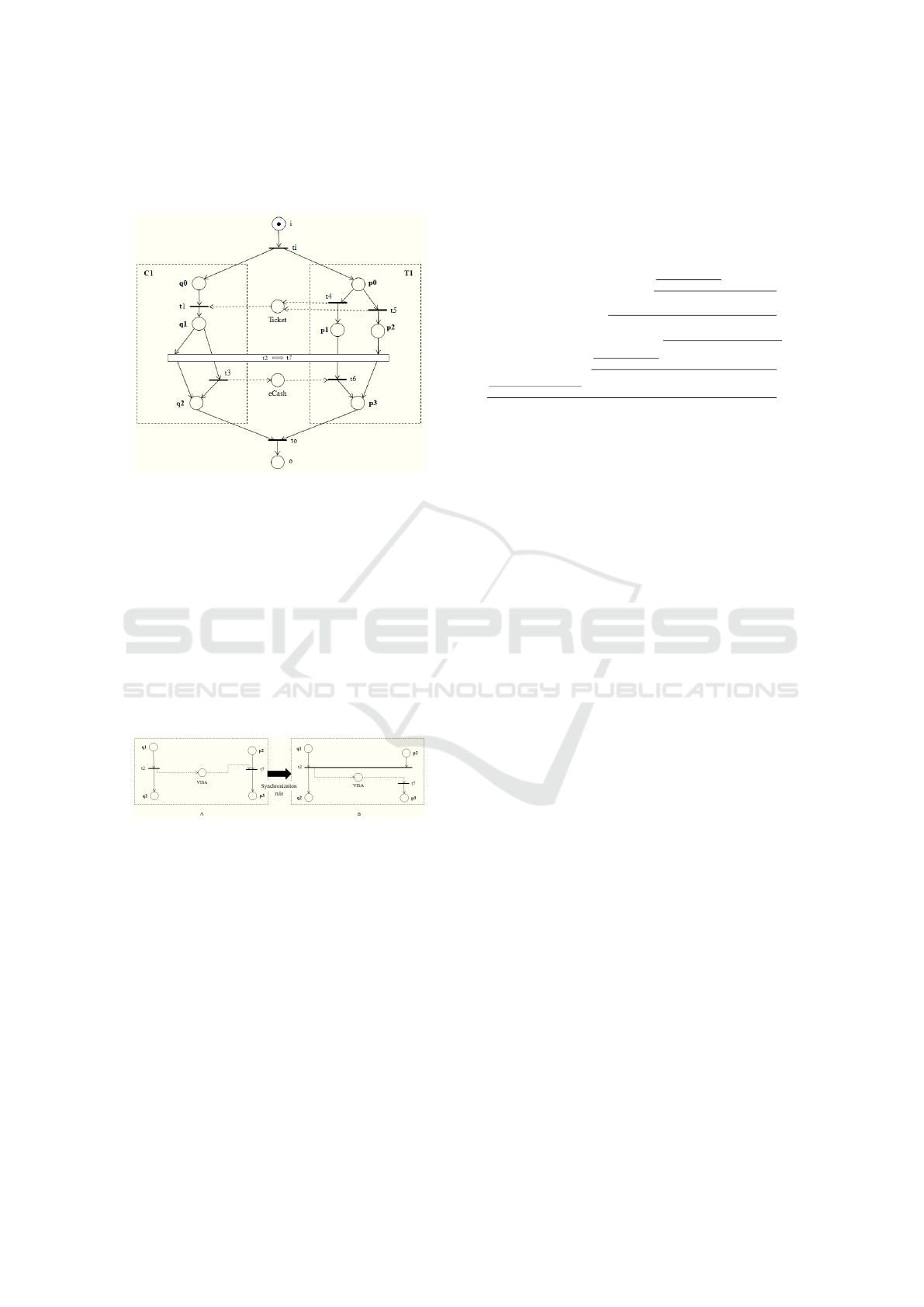
Figure 1: Modules Customer (C1) and Ticket (T1).
To clarify the concept defined above, consider
the modules C1 and T1 of Figure 1, presented in
(Martens, 2005). The module C1 represents a cus-
tomer and the module T1 models a Ticket service.
The internal places of C1 are places q0, q1 and q2.
The input place of C1 is the place Ticket and the out-
put places of C1 are V ISA and eCash.
According to (Martens, 2005), two modules are
called syntactically compatible if both internal pro-
cesses are disjoint and each common place is an out-
put place of one module and an input place of the
other. By considering the modules C1 and T1 shown
in Figure 1, it is easily recognizable that these mod-
ules are syntactically compatible. In the approach
presented in (Martens, 2005), when two modules are
composed, their common places are merged and the
dangling input and output places become the new
interface. To achieve a syntactically correct work-
flow module, it is necessary to add new components
for initialization and termination. In this context,
(Martens, 2005) defined the composed system con-
cept presented in Definition 3.
Definition 3 (Composed System). Let A =
(P
a
,T
a
,F
a
) and B = (P
b
,T
b
,F
b
) be two syntacti-
cally compatible modules. Let i,o /∈ (P
a
∪ P
b
)
be two new places and t
i
,t
o
/∈ (T
a
∪ T
b
) two
new transitions. The composed system A ⊕ B
is given by (P
s
,T
s
,F
s
), such that P
s
= P
a
∪ P
b
∪
A Linear Logic based Synchronization Rule for Deadlock Prevention in Web Service Composition
317

{i,o}, T
s
= T
a
∪ T
b
∪ {t
i
,t
o
} and F
s
= F
a
∪ F
b
∪
{(i,t
i
),(t
i
,α
a
),(t
i
,α
b
),(ω
a
,t
o
),(ω
b
,t
o
),(t
o
,o)}.
Figure 2: The composed system C1 ⊕ T1.
As an example, Figure 2 shows the composed sys-
tem C1 ⊕ T1. Note that the Ticket service (T1) solves
an internal conflict and sends the Ticket to the cus-
tomer module C1. Thereafter, module T1 is either in
state p1 waiting for eCash only, or in state p2 waiting
for V ISA only. The customer (C1) receives the Ticket
and has the choice between either kind of payment,
V ISA or eCash. It is important to note that module C1
does not know the internal state of module T1, i.e. p1
or p2. According to (Martens, 2005), when an inter-
nal decision is made and is not communicated prop-
erly to an external WS, a problem, already well un-
derstood by literature happens - the non local choice
problem that can be responsible for the occurrence of
deadlock situations.
Linear Logic was proposed in 1987 by Girard (Gi-
rard, 1987). In Linear Logic, propositions are consid-
ered as resources which are consumed and produced
at each state change (Riviere et al., 2001). In this pa-
per just two connectives of Linear Logic will be used:
• The times connective, denoted by ⊗, represents
simultaneous availability of resources.
• The linear implies connective, denoted by (,
represents a state change.
The translation of a Petri net into formulas of Lin-
ear Logic (Riviere et al., 2001) is a relatively simple
process: a marking M is a monomial in ⊗ and is rep-
resented by M = A
1
⊗ A
2
⊗ ... ⊗ A
k
where A
i
are
place names; a sequent M,t
i
` M’ represents a sce-
nario where M and M’ are respectively the initial and
final markings, and t
i
is a list of non-ordered transi-
tions; a sequent can be proven by applying the rules of
the sequent calculus. It was proven in (Girault et al.,
1997) that a proof of the sequent calculus is equiva-
lent to a reachability problem in a Petri net model.
In this paper, just some Linear Logic rules will be
considered. These rules will be used to build proof
trees. To achieve this, F, G, and H will be consid-
ered as formulas and Γ and ∆ as blocks of formulas.
The following rules will be those used in this paper
(Riviere et al., 2001):
• The (
L
rule,
Γ ` F ∆,G ` H
Γ,∆, F ( G ` H
(
L
, expresses a
transition firing and generates two sequents, such
that the right sequent represents the subsequent,
which remains to be proven and the left sequent
represents the tokens consumed by this firing.
• The ⊗
L
rule,
Γ,F,G ` H
Γ,F ⊗ G ` H
⊗
L
transforms a
marking in a list of atoms.
• The ⊗
R
rule,
Γ ` F ∆ ` G
∆,Γ ` F ⊗G
⊗
R
transforms a se-
quent such as A,B ` A ⊗ B into two identity se-
quents A ` A and B ` B.
In the approach presented in this paper, a Linear
Logic proof tree is read from the bottom-up. The
proof stops when the atom that represents the place
o is produced, i.e. the identity sequent o ` o appears
in the proof tree, when there is not any rule that can
be applied or when all the leaves of the proof tree are
identity sequents.
3 SYNCHRONIZATION RULE
The approach proposed in this paper considers the
WS composition modeled by workflow modules that
are deadlock-free. Such a statement does not neces-
sarily mean that the composed system is deadlock-
free. In such systems, the addition of the interface
(common places merged among modules) can lead
to situations where some activities are “unreachable”
(Klai et al., 2013), causing the deadlock situation. Ac-
cording to (van der Aalst, 1998), in the context of WF-
nets, a deadlock situation can be corrected by replac-
ing an asynchronous communication element (a com-
munication place) by a synchronous communication
element (a transition of synchronization).
The approach in this paper consists of replacing
some of the asynchronous communication places (in-
terface) of the composed system with new commu-
nication mechanisms partially synchronous in order
to prevent the occurrence of lost messages that, in
case of deadlock situations, are generally trapped in-
side one of the communication places, thus preventing
the composed system from respecting the deadlock-
freeness property. Such a substitution can be seen
therefore as a kind of synchronization rule.
ICEIS 2017 - 19th International Conference on Enterprise Information Systems
318

To apply such a synchronization rule, it is nec-
essary first to identify scenarios responsible for
deadlock situations and more specifically the asyn-
chronous communication elements that can lead the
system to inconsistent states (terminal states with a
token trapped in one or more of the asynchronous
communication places). The detection of inconsistent
states in this work will be based on Linear Logic se-
quent proof trees that correspond to potential scenar-
ios in a composed system.
Initially, the elements of the composed system
have to be represented through the use of Linear Logic
formulas. For each potencial scenario of the com-
posed system, a Linear Logic sequent is then pro-
duced. The detailed method for the obtaining of all
Linear Logic sequent candidates for possible collab-
orations among two or more workflow processes was
presented in (Passos and Julia, 2013).
As shown in (Passos and Julia, 2013), a scenario in
the context of WF-nets corresponds to a well defined
route mapped into the corresponding module, and if
the module has more than one route (places with two
or more output arcs), it is necessary then to build a
different Linear Logic sequent for each existing sce-
nario. After the definition of the Linear Logic se-
quents that represent all the possible scenarios of the
composed system, these Linear Logic sequents need
to be proven through the building of Linear Logic
proof trees.
If the last sequent of a Linear Logic proof tree
built for a specific scenario is different from the iden-
tity sequent o ` o, then there is no token in the sink
place of the composed system, i.e. a deadlock situa-
tion occurs before the termination of the process (Pas-
sos and Julia, 2013).
In the present method, it is necessary to identify
the last transition fired before the occurrence of the
deadlock situation. This transition will be called t
d1
.
To identify such a transition t
d1
, it is necessary to ver-
ify in a Linear Logic proof tree leading to a deadlock
situation, the transition firing that produces the atom
which remains in one of the communication places
(interface) until the conclusion of the Linear Logic
proof tree. For each transition of type t
d1
, a corre-
sponding transition of type t
d2
exists. Such a tran-
sition, when a deadlock situation occurs, is the out-
put transition of a marked communication place that
corresponds to an atom trapped in the interface of
the composed system. The deadlock situation corre-
sponds therefore to the death of transition t
d2
(tran-
sition not enabled until the end of the Linear Logic
proof).
In order to prevent the death of transition t
d2
, it is
necessary to introduce a kind of synchronization rule
that corresponds to the following scheduling strategy:
each time a transition of type t
d1
is fired, the corre-
sponding transition of type t
d2
has to be fired in se-
quence in order to empty the communication place
in which an atom was produced. In practice, such
a policy corresponds to the guarantee that for each
message (the activity associated to the transition t
d1
)
sent by a local process WS, the corresponding answer
of the local workflow module (the activity associated
to the transition t
d2
) will occur with certainty. After
the synchronization rule application, the cause of the
deadlock (a token trapped in a communication place)
is removed and the Linear Logic proof can be cor-
rectly finalized with, as the final state, a single atom
produced in the place o (last place of the composed
system).
To illustrate the approach, the composed sys-
tem shown in Figure 2 is considered. As shown
in (Martens, 2005), the modules Customer (C1) and
Ticket (T1) shown in Figure 1 that make up the com-
posed system are deadlock-free but the composed sys-
tem of Figure 2 is not deadlock-free.
For the composed system shown in Figure 2, there
exist four different scenarios to be studied. The first
scenario, Sc
1
, where transitions t
3
and t
4
will be fired.
The second scenario, Sc
2
, where transitions t
2
and t
5
will be fired. The third scenario, Sc
3
, where transi-
tions t
2
and t
4
will be fired. Finally, the fourth sce-
nario, Sc
4
, where transitions t
3
and t
5
will be fired.
Each one of these scenarios is then represented by
a specific Linear Logic sequent that considers the ini-
tial and final markings of the composed system and
a non-ordered list of transitions involved in it (Passos
and Julia, 2015).
The transitions of the composed system shown in
Figure 2 are represented by the following formulas of
Linear Logic:
t
i
= i ( q0 ⊗ p0, t
1
= q0 ⊗ Ticket ( q1,
t
2
= q1 ( V ISA ⊗ q2, t
3
= q1 ( eCash ⊗ q2,
t
4
= p0 ( Ticket ⊗ p1, t
5
= p0 ( Ticket ⊗ p2,
t
6
= p1 ⊗ eCash ( p3, t
7
= p2 ⊗V ISA ( p3,
t
o
= q2 ⊗ p3 ( o.
The four different scenarios, and consequently
Linear Logic sequents, are thus the following:
Sc
1
= i, t
i
, t
1
, t
3
, t
4
, t
6
, t
o
` o,
Sc
2
= i, t
i
, t
1
, t
2
, t
5
, t
7
, t
o
` o,
Sc
3
= i, t
i
, t
1
, t
2
, t
4
, t
6
, t
o
` o,
Sc
4
= i, t
i
, t
1
, t
3
, t
5
, t
7
, t
o
` o.
Presented in the following are the Linear Logic
proof trees for each of these scenarios. For a better
analysis of the approach, the proof tree for scenario
Sc
1
was divided into two parts, remembering that a
Linear Logic proof tree is read from the bottom-up.
Part 1 of the proof tree for scenario Sc
1
is in black
A Linear Logic based Synchronization Rule for Deadlock Prevention in Web Service Composition
319

text, while Part 2 of the proof for scenario Sc
1
is in
blue text. The proof tree for scenario Sc
1
is as follows:
q2`q2 p3`p3
q2,p3`q2⊗p3
⊗
R
o`o
(
L
p1`p1 eCash`eCash
p1,eCash`p1⊗eCash
⊗
R
q2,p3,q2⊗p3(o`o
(
L
p1,eCash,q2,p1⊗eCash( p3,t
o
`o
⊗
L
q1`q1 p1,eCash⊗q2,t
6
,t
o
`o
(
L
q0`q0 Ticket`Ticket
q0,Ticket`q0⊗Ticket
⊗
R
p1,q1,q1(eCash⊗q2,t
6
,t
o
`o
(
L
q0,Ticket,p1,q0⊗Ticket(q1,t
3
,t
6
,t
o
`o
⊗
L
p0`p0 q0,Ticket⊗p1,t
1
,t
3
,t
6
,t
o
`o
(
L
q0,p0,t
1
,t
3
,p0(Ticket⊗p1,t
6
,t
o
`o
⊗
L
i`i q0⊗p0,t
1
,t
3
,t
4
,t
6
,t
o
`o
(
L
i,i(q0⊗p0,t
1
,t
3
,t
4
,t
6
,t
o
`o
For a better analysis of the approach, the Linear
Logic proof tree for scenario Sc
2
was also divided into
two parts. Part 1 of the proof tree for scenario Sc
2
is
in black text, while Part 2 of the proof for scenario
Sc
1
is in blue text. The proof tree for scenario Sc
2
is
as follows:
q2`q2 p3`p3
q2,p3`q2⊗p3
⊗
R
o`o
(
L
p2`p2 VISA`VISA
p2,V ISA`p2⊗V ISA
⊗
R
q2,p3,q2⊗p3(o`o
(
L
p2,VISA,q2,p2⊗V ISA( p3,t
o
`o
⊗
L
q1`q1 p2,VISA⊗q2,t
7
,t
o
`o
(
L
q0`q0 Ticket`Ticket
q0,Ticket`q0⊗Ticket
⊗
R
p2,q1,q1(VISA⊗q2,t
7
,t
o
`o
(
L
q0,Ticket,p2,q0⊗Ticket(q1,t
2
,t
7
,t
o
`o
⊗
L
p0`p0 q0,Ticket⊗p2,t
1
,t
2
,t
7
,t
o
`o
(
L
q0,p0,t
1
,t
2
,p0(Ticket⊗p2,t
7
,t
o
`o
⊗
L
i`i q0⊗p0,t
1
,t
2
,t
5
,t
7
,t
o
`o
(
L
i,i(q0⊗p0,t
1
,t
2
,t
5
,t
7
,t
o
`o
The proof tree for scenario Sc
3
is the following:
p1,VISA,q2,t
6
,t
o
`o
⊗
L
q1`q1 p1,VISA⊗q2,t
6
,t
o
`o
(
L
q0`q0 Ticket`Ticket
q0,Ticket`q0⊗Ticket
⊗
R
p1,q1,q1(VISA⊗q2,t
6
,t
o
`o
(
L
q0,Ticket,p1,q0⊗Ticket(q1,t
2
,t
6
,t
o
`o
⊗
L
p0`p0 q0,Ticket⊗p1,t
1
,t
2
,t
6
,t
o
`o
(
L
q0,p0,t
1
,t
2
,p0(Ticket⊗p1,t
6
,t
o
`o
⊗
L
i`i q0⊗p0,t
1
,t
2
,t
4
,t
6
,t
o
`o
(
L
i,i(q0⊗p0,t
1
,t
2
,t
4
,t
6
,t
o
`o
And finally the proof tree for scenario Sc
4
is as
follows:
p2,eCash,q2,t
7
,t
o
`o
⊗
L
q1`q1 p2,eCash⊗q2,t
7
,t
o
`o
(
L
q0`q0 Ticket`Ticket
q0,Ticket`q0⊗Ticket
⊗
R
p2,q1,q1(eCash⊗q2,t
7
,t
o
`o
(
L
q0,Ticket,p2,q0⊗Ticket(q1,t
3
,t
7
,t
o
`o
⊗
L
p0`p0 q0,Ticket⊗p2,t
1
,t
3
,t
7
,t
o
`o
(
L
q0,p0,t
1
,t
3
,p0(Ticket⊗p2,t
7
,t
o
`o
⊗
L
i`i q0⊗p0,t
1
,t
3
,t
5
,t
7
,t
o
`o
(
L
i,i(q0⊗p0,t
1
,t
3
,t
5
,t
7
,t
o
`o
The last sequent in the proof trees for scenarios
Sc
1
and Sc
2
is o ` o; then these are deadlock-free sce-
narios. The last sequent for scenario Sc
3
is p1, V ISA,
q2, t
6
, t
o
` o and the last sequent for scenario Sc
4
is
p2, eCash, q2, t
7
, t
o
` o; then scenarios Sc
3
and Sc
4
are the scenarios where the deadlock situations occur.
It is then necessary to apply the synchronization rule
in each of these scenarios to remove the deadlock.
Considering first scenario Sc
3
, the last transition
that was fired before the deadlock situation is transi-
tion t
2
marked in bold type in the proof tree. In partic-
ular, the last atoms q2 and V ISA of the last sequent of
the proof tree for scenario Sc
3
are produced when the
transition t
2
is fired. However, due to the deadlock sit-
uation, these atoms are not consumed at the end of the
proof. Hence, transition t
2
will correspond to a transi-
tion of type t
d1
of the approach, transition t
7
to a tran-
sition of type t
d2
, and the atom V ISA to the marked
asynchronous communication place (interface).
The asynchronous communication place VISA,
present in the last sequent of the proof tree of scenario
Sc
3
, is an output place of transition t
2
(last transition
fired in the proof tree). This communication place is
the input place of transition t
7
of module T1. There-
fore, transition t
7
corresponds, in scenario Sc
3
, to a
dead transition.
Figure 3 shows the synchronization rule applica-
tion in scenario Sc
3
of the composed system shown in
Figure 2. The synchronization rule, shown in Figure
3, is not a true transition; it is a transition rule that
synchronizes part of the communication structure be-
tween the modules C1 and T1. The transformation
of the pure asynchronous communication mechanism
into a partial synchronous mechanism after the appli-
cation of the synchronization rule is presented in Fig-
ure 4. In Figure 4A, the firing of transition t
2
(transi-
tion of type t
d1
) corresponds only to a necessary con-
dition for the firing of transition t
7
(transition of type
t
d2
). Such an asynchronous communication protocol
does not provide a guarantee for the receiving of a
ICEIS 2017 - 19th International Conference on Enterprise Information Systems
320
sent message; in particular, for scenario Sc
3
, after the
firing of transition t
2
, a token will remain trapped in
the communication place V ISA.
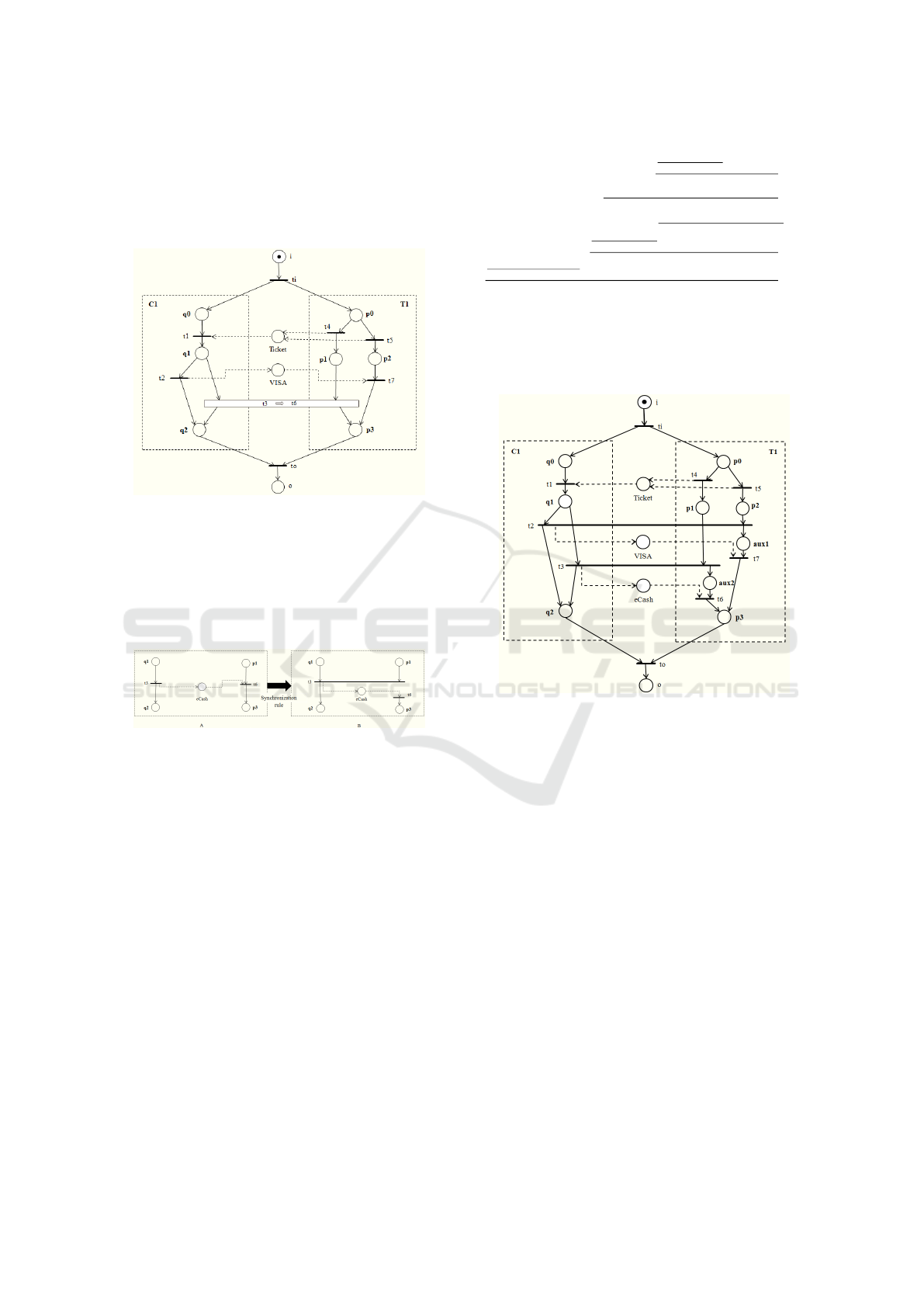
Figure 3: Applying the synchronization rule in scenario Sc
3
of the composed system shown in Figure 2.
On the contrary, in Figure 4B, the fact of synchro-
nizing the execution of the first activity associated to
transition t
2
(transition of type t
d1
) on both modules
C1 and T1, corresponds to guaranteeing the execu-
tion of the called activity t
7
(transition of type t
d2
). In
fact, the firing of a transition of type t
d1
, after the ap-
plication of the synchronization rule, corresponds to
a necessary and sufficient condition for the firing of
the transition of type t
d2
, and at the end of the associ-
ated scenario, no token will remain in any intermedi-
ary communication place.
Figure 4: Before and after the application of the synchro-
nization rule to scenario Sc
3
.
After the synchronization rule application, the
deadlock situation is removed and scenario Sc
3
will
not be able to occur in the composed system. In prac-
tice, scenario Sc
3
is then removed from potential sce-
narios that exist when considering the composed sys-
tem shown in Figure 2.
According to Figure 4B, transitions t
2
and t
7
of the
composed system are modified after the synchroniza-
tion rule. They are now represented by the following
new formulas of Linear Logic:
t
2
= q1 ⊗ p2 ( V ISA ⊗ q2, t
7
= V ISA ( p3.
Transitions t
2
and t
7
do not appear in the Linear
Logic sequents of scenario Sc
1
and Sc
4
, and the alter-
ation of the model does not modify the proof trees of
the corresponding scenarios. On the other hand, both
transitions appear in scenario Sc
2
. Part 1 of the proof
tree for scenario Sc
2
continues unchanged after the
application of the synchronization rule. Part 2 of the
proof tree needs to be computed again and becomes
then:
q2`q2 p3`p3
q2,p3`q2⊗p3
⊗
R
o`o
(
L
V ISA`V ISA q2,p3,q2⊗p3(o`o
(
L
V ISA,q2,V ISA( p3,t
o
`o
⊗
L
q1`q1 p2`p2
q1,p2`q1⊗p2
⊗
R
V ISA⊗q2,t
7
,t
o
`o
(
L
q0`q0 Ticket`Ticket
q0,Ticket`q0⊗Ticket
⊗
R
p2,q1,q1⊗p2(V ISA⊗q2,t
7
,t
o
`o
(
L
.
.
.
The last sequent in the proof tree for the new sce-
nario Sc
2
is o ` o; as a consequence, after the applica-
tion of the synchronization rule, scenario Sc
2
is still a
deadlock-free scenario.
Since the model has more than one deadlock sce-
nario, it is also necessary to apply the synchronization
rule to scenario Sc
4
. Considering now scenario Sc
4
,
the last transition that was fired before the deadlock
situation is transition t
3
marked in bold type in the
proof tree. In particular, the last atoms q2 and eCash
of the last sequent of the proof tree for scenario Sc
4
are produced when the transition t
3
is fired. How-
ever, due to the deadlock situation, these atoms are
not consumed at the end of the proof tree. Therefore,
transition t
3
will correspond to a transition of type t
d1
,
transition t
6
to a transition of type t
d2
, and atom eCash
to the marked asynchronous communication place.
The asynchronous communication place eCash
present in the last sequent of the proof tree of scenario
Sc
4
is an output place of transition t
3
(last transition
fired in the proof tree). This communication place is
the input place of transition t
6
of module T1. Hence,
transition t
6
corresponds, in scenario Sc
4
, to the dead
transition.
Figure 5 shows the synchronization rule applica-
tion in scenario Sc
4
of the composed system as shown
in Figure 2. As mentioned in scenario Sc
3
, the syn-
chronization rule, shown in Figure 5, is not a true tran-
sition; it is a transition rule that synchronizes part of
the communication structure between the modules C1
and T1. The transformation of the pure asynchronous
communication mechanism into a partial synchronous
mechanism after the application of the synchroniza-
tion rule is presented in Figure 6. In Figure 6A, the
firing of transition t
3
(transition of type t
d1
) corre-
sponds only to a necessary condition for the firing of
transition t
6
(transition of type t
d2
). Such an asyn-
A Linear Logic based Synchronization Rule for Deadlock Prevention in Web Service Composition
321
chronous communication protocol is therefore, not a
guarantee for the receiving of a sent message. In par-
ticular, for scenario Sc
4
, after the firing of transition
t
3
, a token will remain trapped in the communication
place eCash.
Figure 5: Applying the synchronization rule to scenario Sc
4
of the composed system as shown in Figure 2.
On the contrary, in Figure 6B, the fact of synchro-
nizing the execution of the first activity associated to
transition t
3
(transition of type t
d1
) on both modules
C1 and T1, corresponds to guaranteeing the execution
of the called activity t
6
(transition of type t
d2
).
Figure 6: Before and after the application of the synchro-
nization rule in scenario Sc
4
.
After the synchronization rule application, the
deadlock situation is removed and scenario Sc
4
will
not be able to occur in the composed system. In prac-
tice, scenario Sc
4
is then removed from potential sce-
narios that exist when considering the composed sys-
tem as shown in Figure 2.
According to Figure 6B, transitions t
3
and t
6
of the
composed system are modified after the synchroniza-
tion rule. They are now represented by the following
new formulas of Linear Logic:
t
3
= q1 ⊗ p1 ( eCash ⊗q2, t
6
= eCash ( p3.
Transitions t
3
and t
6
do not appear in the Linear
Logic sequents of scenario Sc
2
and the alteration of
the model do not modify the proof tree of the corre-
sponding scenario. On the other hand, both transi-
tions appear in scenario Sc
1
. Part 1 of the proof tree
for scenario Sc
1
continue unchanged after the appli-
cation of the synchronization rule. Part 2 of the proof
tree needs to be computed again, and becomes then:
q2`q2 p3`p3
q2,p3`q2⊗p3
⊗
R
o`o
(
L
eCash`eCash q2,p3,q2⊗p3(o`o
(
L
eCash,q2,eCash( p3,t
o
`o
⊗
L
q1`q1 p1`p1
q1,p1`q1⊗p1
⊗
R
eCash⊗q2,t
6
,t
o
`o
(
L
q0`q0 Ticket`Ticket
q0,Ticket`q0⊗Ticket
⊗
R
p1,q1,q1⊗p1(eCash⊗q2,t
6
,t
o
`o
(
L
.
.
.
The last sequent in the proof tree for the new sce-
nario Sc
1
is o ` o; then after the application of the
synchronization rule, scenario Sc
1
is still a deadlock-
freeness scenario.
Figure 7: Final model after the application of the synchro-
nization rule.
Figure 7 shows the final model after the synchro-
nization rule application in scenario Sc
3
and Sc
4
of
the composed system shown in Figure 2. Note that
additional places aux1 e aux2 were produces in the fi-
nal model in order to respect the workflow module
definition (as a matter of fact, transitions t
6
and t
7
need at least one input transition in order to respect
the basic structure of a WF-net). Such places, con-
sidering the Petri net theory (Murata, 1989), are im-
plicit places and do not alter the good properties of
the corresponding model; then the results produced
by the study of Linear Logic proof trees (removal of
the scenarios leading to deadlock situations) will still
be valid. In particular, the deadlock scenarios Sc
3
and
Sc
4
are removed from the final model, with only the
two deadlock-free scenarios remaining, Sc
1
and Sc
2
.
Remembering here that scenarios Sc
1
and Sc
2
were
slightly modified after the synchronization rule appli-
cation.
A great advantage of the Linear Logic based ap-
proach presented in this paper is that when a deadlock
ICEIS 2017 - 19th International Conference on Enterprise Information Systems
322

situation occurs, only the asynchronous part of the
net altered by the synchronous rule needs to be repro-
cessed; the rest of the Linear Logic proof tree will re-
main unaltered. Therefore, the analysis of the model
only happens on the modified part of the model.
4 CONCLUSIONS
This paper presented an approach to prevent dead-
lock situations in WS compositions modeled by Petri
nets. In WS Composition where the workflow mod-
ules are deadlock-free, deadlock problems can occur
at the level of a composed system (collaboration be-
tween at least two workflow modules). Generally, it
is the interface (communication places between the
workflow modules) that provokes the deadlock situa-
tion. The synchronization rule presented in this paper
implements a kind of local scheduling strategy that
guarantees that each time a message is sent, the corre-
sponding answer of the local workflow module will,
in fact, occur.
The advantages of such an approach are diverse.
The proposed method is based on the construction and
analysis of proof trees of Linear Logic that represent
scenarios of a composed system. As was shown in
(Passos and Julia, 2009), the time complexity to prove
a Linear Logic sequent that corresponds to a scenario
of a workflow process is linear. The fact of working
with Linear Logic permits the identification of com-
munication places (interface) responsible for the oc-
currence of deadlock situations. Furthermore, work-
ing with Linear Logic, it is possible to reuse unaltered
fragments of a proof tree produced before the appli-
cation of the synchronization rule i.e. the analysis of
the model is only executed on the part of the model
responsible for the deadlock.
As a future work proposal, it will be interesting to
propose a kind of quantitative analysis based on sym-
bolic dates, considering in this manner the proof trees
of Linear Logic with dates, as presented in (Riviere
et al., 2001). Such an analysis will be able to evaluate
the effect of the synchronization rule on the perfor-
mance of the system.
ACKNOWLEDGEMENTS
The authors would like to thank FAPEMIG, FAPERJ,
CNPq and CAPES for financial support.
REFERENCES
Barros, A., Dumas, M., and Oaks, P. (2005). Standards
for Web Service Choreography and Orchestration:
Status and Perspectives. In International Confer-
ence on Business Process Management, pages 61–74.
Springer.
Girard, J.-Y. (1987). Linear logic. Theoretical computer
science, 50(1):1–101.
Girault, F., Pradier-Chezalviel, B., and Valette, R. (1997).
A logic for Petri nets. Journal europ
´
een des syst
`
emes
automatis
´
es, 31(3):525–542.
Klai, K., Ochi, H., and Tata, S. (2013). Formal abstraction
and compatibility checking of Web services. In Web
Services (ICWS), 2013 IEEE 20th International Con-
ference on, pages 163–170. IEEE.
Martens, A. (2005). Analyzing Web Service Based Busi-
ness Processes. In International Conference on Fun-
damental Approaches to Software Engineering, pages
19–33. Springer.
Murata, T. (1989). Petri nets: Properties, Analysis and Ap-
plications. Proceedings of the IEEE, 77(4):541–580.
Passos, L. M. S. and Julia, S. (2009). Qualitative Analy-
sis of WorkFlow nets using Linear Logic: Soundness
Verification. In Systems, Man and Cybernetics, 2009.
SMC 2009. IEEE International Conference on, pages
2843–2847. IEEE.
Passos, L. M. S. and Julia, S. (2013). Qualitative Analy-
sis of Interorganizational WorkFlow nets using Linear
Logic: Soundness Verification. In 2013 IEEE 25th
International Conference on Tools with Artificial In-
telligence, pages 667–673. IEEE.
Passos, L. M. S. and Julia, S. (2015). Deadlock-Freeness
Scenarios Detection in Web Service Composition.
In Information Technology-New Generations (ITNG),
2015 12th International Conference on, pages 780–
783. IEEE.
Riviere, N., Pradin-Chezalviel, B., and Valette, R. (2001).
Reachability and temporal conflicts in t-time Petri
nets. In Petri Nets and Performance Models, 2001.
Proceedings. 9th International Workshop on, pages
229–238. IEEE.
van der Aalst, W. M. P. (1998). Modeling and Analyzing
Interorganizational Workflows. In International Con-
ference on Application of Concurrency to System De-
sign, pages 262–272.
van der Aalst, W. M. P., van Hee, K. M., ter Hofstede, A.
H. M., Sidorova, N., Verbeek, H. M. W., Voorhoeve,
M., and Wynn, M. T. (2011). Soundness of workflow
nets: classification, decidability, and analysis. Formal
Aspects of Computing, 23(3):333–363.
Xiong, P., Fan, Y., and Zhou, M. (2010). A Petri Net
Approach to Analysis and Composition of Web Ser-
vices. IEEE Transactions on Systems, Man, and
Cybernetics-Part A: Systems and Humans, 40(2):376–
387.
A Linear Logic based Synchronization Rule for Deadlock Prevention in Web Service Composition
323
