
Model-based Development of Modular Complex Systems for
Accomplishing System Integration for Industry 4.0
Kunal Suri
1,2
, Arnaud Cuccuru
1
, Juan Cadavid
1
, Sebastien Gerard
1
, Walid Gaaloul
2
and Samir Tata
3,2
1
CEA, LIST, Laboratory for Model-driven Engineering for Embedded Systems, P.C. 174, 91191, Gif-sur-Yvette, France
2
Telecom SudParis, UMR 5157 Samovar, Université Paris-Saclay, Evry, France
3
IBM Research, San Jose, CA, U.S.A.
Keywords:
Industry 4.0, Smart Factory, Model-driven Engineering, MDE, Model Execution, UML, Modularity, Integra-
tion, CPS, Lego EV3 Robot.
Abstract:
Industry 4.0 provides a framework for integration of cyber-physical systems (CPS), internet of things (IoT),
internet of services (IoS) and internet of data (IoD) with the manufacturing domain so as to make it smart, flex-
ible and adaptable to the dynamic market changes and the customer requirements. It will enable companies
to form a connected "smart manufacturing" ecosystem having interconnections between the suppliers, manu-
facturers, distributors and even the products in order to provide better services to the end customer. However,
due to the presence of heterogeneous systems that might not adhere to the industrial standards, there is a gap
in achieving this vision of an interconnected ecosystem. In this paper, we focus on providing a solution for
the modularity and interoperability issues related to the Industry 4.0 from a systems integration viewpoint.
We propose a model-based approach for modular complex systems development by separating (1) the behav-
ior model and (2) the implementation logic (execution) of the system. Moreover, we use unified modeling
language (UML) based modeling techniques to model system behavior and connect the behavior models to
the application programming interface (API) of the CPS. Thus, instead of generating source code for the CPS
using models, we directly execute the CPS in the physical world via model execution. The model execution is
supported by the standard execution semantics of UML. Using our approach, multiple heterogeneous systems
can be modeled and integrated together to create a "plug and play" ecosystem needed for achieving the vision
of Industry 4.0.
1 INTRODUCTION
In recent years, the dawn of the forth Industrial rev-
olution (Industry 4.0) has created a great enthusiasm
among companies and researchers by providing them
an opportunity to pave the path towards the vision of
the "smart factory". This interest in Industry 4.0 is due
to the fact that, it is for the first time in the history of
an industrial revolution that, it has been predicted a-
priori, rather than being observed ex-post (Hermann
et al., 2016). Industry 4.0 provides a framework for
integration of CPS, IoT, IoS, IoD with the manufac-
turing domain to make it smart, flexible and adapt-
able to the dynamic market changes and the customer
requirements. It is envisioned to have a great eco-
nomic impact for companies in many ways, such as,
enabling factories to be reconfigured over a weekend
instead of taking a month, creating customized prod-
ucts for the end users, reducing wastage of resources
such as energy. It will provide the possibility of cre-
ating new business opportunities by making efficient
use of human resources and having end to end con-
nected supply chain management. Additionally, In-
dustry 4.0 is based on six design principles which
are, interoperability, virtualization, decentralization,
real-time capability, service orientation and modular-
ity (Hermann et al., 2016). Moreover, it is this very
need for creation of new business opportunities that
requires the factories to be flexible (for e.g. easy re-
configuration) in context of Industry 4.0.
Furthermore, the system integration can be seen
from two viewpoints, as shown in figure 1, (1) hor-
izontal integration and (2) vertical integration. The
horizontal integration (or inter-company integration)
will be the base for a strong collaboration between
various companies and their stake-holders. These
companies will interact with each other and create a
seamless inter-connected ecosystem. Moreover, for
Suri K., Cuccuru A., Cadavid J., Gerard S., Gaaloul W. and Tata S.
Model-based Development of Modular Complex Systems for Accomplishing System Integration for Industry 4.0.
DOI: 10.5220/0006210504870495
In Proceedings of the 5th International Conference on Model-Driven Engineering and Software Development (MODELSWARD 2017), pages 487-495
ISBN: 978-989-758-210-3
Copyright
c
2017 by SCITEPRESS – Science and Technology Publications, Lda. All rights reserved
487
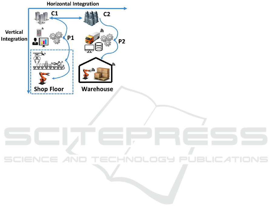
these systems to be interoperable they need to be de-
veloped in a platform-independent manner based on
industrial standards. This will enable them to ex-
change data or information and avoid vendor lock-
in issues. In the same way, the vertical integration
(or intra-company integration) shall also be based on
standards.
Figure 1: Vertical and Horizontal Integration.
In this paper, we focus on the "vertical integration"
of system using the model-driven engineering (MDE)
approach. In vertical integration the models (for e.g.
a production process model) that are modeled by a
certain stakeholder (for e.g. production analysts) will
have a traceable link with other fine-grained models
(for e.g. a robots behavior models) modeled by an-
other stakeholder (for e.g. a systems engineer). This
traceability will help in achieving a better manage-
ment of information between various layers within an
organization along with a better impact analysis of
the changes made in different layers. Moreover, as
these models are based on standards, the same mod-
els can be used for the purpose of simulation and
also for execution of the systems that they depict.
For instance, the execution of a industrial robot on
a shop floor will benefit from the model-based execu-
tion approach wherein, there is a separation between
its behavior model (control flow) and its actual im-
plementation logic. The behavior can be modeled us-
ing industrial standard such as, the unified modeling
language (UML) activity diagram that will describe
"how to achieve a certain task". These models can
be used to perform simulations for depicting how the
system works. The same models will then be exe-
cuted based on the standardized semantics of UML
model execution. As, the semantics of UML model
execution provides a standard mechanism to connect
and communicate with external software and tools, it
will allow the models to communicate and execute the
robots in the physical world via standard APIs of the
robots firmware .
In contrast to the state of the art of model-driven
approaches in robotics, we view our approach based
on model execution as an "on-line" execution. In
our approach the CPS executes live in sync with the
model being executed, where as, in most of the other
model-based approaches the models are used to create
source code for the CPS which is then installed on it
making it a "of-line" execution. In other words, rather
than creating source code from our models, we di-
rectly execute the CPS in the physical world through
model execution. This provides a good mechanism
for tackling co-simulation problem for CPS (Rahman
and Mizukawa, 2013)
Moreover, for simplicity reasons, we consider a
simple robot as one of the concrete depiction of a
CPS in context of the Industry 4.0. We validated our
approach by using a Lego EV3 robot (EV3, 2013)
installed with an open-source java based firmware
called LeJOS (Lejos, 2015). The model design and
model execution is performed using Papyrus frame-
work (Papyrus, 2016) .
This article is structured as follows. Section 2 de-
scribes the context of this work in relation to com-
plex system development and model-driven engineer-
ing (MDE) for Industry 4.0. Section 3 provides some
insight on the related work. Section 4 describes our
approach followed with experimentation in Section 5.
This is followed by discussion in Section 6. We con-
clude our paper in Section 7.
2 CONTEXT
2.1 Industry 4.0 and Smart Factory
One of the goals for the Industry 4.0 vision is to cre-
ate manufacturing ecosystems that are smart, flexible
and adaptable to dynamic market changes and cus-
tomer requirements. Such smart factories will under-
stand the state of a production process and will react
accordingly with minimal human intervention. More-
over, in case of system fault if the cyber-physical sys-
tem (CPS) or the cyber-physical production systems
(CPPS) needs human support, the system itself will
assist the humans with appropriate contextual infor-
mation to avoid cognitive overload on them (Wieland
et al., 2010).
Recently, various research in context of Industry
4.0 is being focused towards understanding howMDE
can benefit the Industry 4.0 vision as a key technol-
ogy enabler. In their recent work, the authors (Ca-
david et al., 2015) provide arguments about the im-
portance of MDE for smart manufacturing and how
MODELSWARD 2017 - 5th International Conference on Model-Driven Engineering and Software Development
488

MDE with its underlying concepts such as, domain
specific modelling languages, modelling abstractions
based on view-points, model-based formal analysis
and automated model transformations would help to
transform the vision of Industry 4.0 into a reality.
2.2 Model-Driven Engineering for
Complex Systems
A complex system, such as a cyber-physical system
(CPS), an industrial robot or a service robot, con-
sists of a large number of component such as, actu-
ators, sensors, auxiliary tools along with the firmware
that are all seamlessly integrated together and need
to work as a single entity. These complex systems
would also interact with other complex systems to
perform certain tasks. Thus, it is very important to
design these complex systems keeping the principle
of modularity in mind so as to allow ease of integra-
tion between various systems.
In addition to above, a complex system also con-
sists of different parts relating to different kinds of
engineering disciplines such as, mechanical, electri-
cal, software. Thus, these systems are required to be
verified and tested both (1) at the componentlevel and
(2) at a system level. Therefore, MDE can help in re-
ducing the inherent complexity of these systems by
providing standard modeling languages, and provid-
ing tools and frameworks that supports various design
principles. For example, using the principles of "sep-
aration of concerns" we can abstract various aspects
of a system and can view only the things that are im-
portant to us, thus reducing complexity.
3 RELATED WORK
In recent years, a number of research contributions in
MDE have been looking at the applications of MDE
in design and execution of complex systems such
as, industrial robots. On the same lines, the authors
(Steck et al., 2011) put forward the importance of
moving from code-driven to model-driven engineer-
ing for industrial-strength service robotic systems.
Their work is focused on the entire life-cycle of robot
development wherein they provide a model-centric
view on the whole (robotic) system covering both the
design time and the run time of the robot. The model-
driven development will support the decision mak-
ing process of a robot during its run-time based on
parameters, properties and resource information that
were modelled at design-time. This will enable it
to handle a large number of situations. Plus, mod-
eling would help to reduce the complexity for differ-
ent stakeholders based on the principle of "separation
of concerns". Similarly, in the work done by (Rah-
man and Mizukawa, 2013), the authors describe the
difficulty faced in achieving a holistic system-level
verification along with the problem of fulfilling the
requirements of different stakeholders using only de-
scriptive systems models (SysML). Thus, they pro-
posed to combine the descriptive and simulation mod-
els by providing a collaborative design framework
which brings SysML, Simulink, and Simscape pro-
files within the domain of robotic modeling.
Likewise, (Inglés-Romeroet al., 2013) express the
need to create a domain specific language (DSL) for
expressing variability for the non-functional proper-
ties for a robotic system. They argue that in con-
text of a service robot there will always be unfore-
seen situations that are needed to be tackled at run-
time but, may have not been modelled at design time.
They used the variability modelling language (VML)
at design time to resolve such problems. The authors
(Gherardi and Brugali, 2014), provide a development
process containing guidelines to exploit existing best
practices and reference architectures for robotic soft-
ware. Similarly, in their work (Romero-Garcés et al.,
2013) present four DSLs wherein each DSL has a
specific perspective for defining a robot component
and are all based on model-driven techniques. They
compare and analyse the effort based on lines of code
for robot development before and after making use of
these DSLs. They argue that these DSLs, reduce the
workload of the developers depending on what "con-
cerns" they need to focus during the robots life-cycle.
They also describe the improvements in flexibility,
scalability and maintenance for RoboComp frame-
work using MDE along with the benefit from model-
to-model, model-to-text transformations approaches
and to generate source code automatically. Other au-
thors, such as, (Schlegel et al., 2015), have described
steps need to create a software business ecosystem
in robotics using model-driven software development
and model-driven software systems integration
Furthermore, in their work (Harrand et al., 2016),
the authors reinforce the benefits of model-based sys-
tems engineering (MBSE) for increasing productiv-
ity by automated code generation from models. They
provide an open-source project called "ThingML"
which includes a modelling language and tool de-
signed for supporting code generation using highly
customizable multi-platform code generator targeting
heterogeneous platforms. Their work may benefit the
heterogeneous systems environment in context of the
Industry 4.0. Other researchers like (Kovalenko et al.,
2015) explored the AutomationML format which is
an emerging data exchange standard for supporting
Model-based Development of Modular Complex Systems for Accomplishing System Integration for Industry 4.0
489
the Industry 4.0 vision. This standards can be repre-
sented via two modelling approaches, MDE and Se-
mantic Web. They pointed out the differences in these
approaches and provide the applications of these ap-
proached for improving the production processes in
manufacturing domain. In context of real-time sys-
tems, the authors (Perseil et al., 2011), presented a
modeling and execution framework through which it
will be possible to analyse, design and verify com-
plex systems. This approach would help to tackle spe-
cific concerns of the real-time and embedded systems
(RTE) domain.
In particluar, (Tatibouët et al., 2014) discussed the
use of UML profile mechanism for designing a DSL
in their work. They arguedthe need for having an exe-
cution semantics for UML profiles as the current pro-
file design methodology only considers the syntactic
part of the language, keeping the execution semantics
description as informal. In their work, they provide
a systematic approach to formalize the execution se-
mantics of UML profiles. To realize their approach
they make use of foundational UML (normative spec-
ification) which defines a precise semantics for a sub-
set of UML.
4 APPROACH
In this section, we describe our approach for de-
velopment and executing of a model-based modu-
lar system using open standards. This approach will
enable heterogeneous systems to communicate with
each other in a cohesive but loose coupled manner.
For our approach, we used Unified Modeling Lan-
guage (UML2.5, 2015), which is a general-purpose,
developmental, modeling language in the field of soft-
ware engineering. Additionally, in this work we de-
pict a cyber-physical system (CPS) as a simple robot
that will expose its functionality using standard APIs
which will be called by the executingbehavior models
(activity model in our case).
4.1 Conceptual Approach
In context of Industry 4.0, we have already estab-
lished the need to develop systems based on indus-
trial standards keeping the principle of modularity in
mind. This will help to achieve interoperability and
a plug and play kind of environment as envisioned
for Industry 4.0. In our approach, we separated the
concerns of developing and executing the robot. The
robot executes based on instructions (events) it re-
ceives from the control flow layer. This, separation
helps to achieve a loose coupled system. In particu-
lar, this approach has been developed keeping indus-
trial robots in mind which perform standard repetitive
tasks. But, these robots need to be flexible (for e.g.
easy to reconfigure) so as to perform new tasks as and
when needed. Also, these robots should be able to
communicate with other similar or non-similar robots
present in the ecosystem of a smart factory.
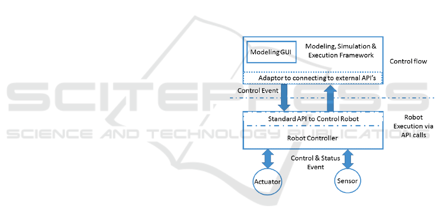
In the figure 2, we show the two separate layers
i.e. the model-based behavior layer (control flow)
and robots implementation layer. In our approach, the
software layer on the robot will be kept as minimal as
possible. The execution of the robot is done using API
calls through an executing model (on-line execution)
rather than deploying the source code on the complex
system (of-line execution). This approach will allow
creation of complex systems having sensors and actu-
ators with low computational power and low energy
usage. In such a setting, the models while executing
would send control events to the software (middle-
ware or firmware) layer of the robots and the robots
should respond to them with status event.
Figure 2: Conceptual Approach for Modular Complex Sys-
tem Development.
4.2 Refinement of the Approach
To concretize the above conceptual approach, we
make use of the Papyrus framework for designing
the models and execution of the EV3 robot. Papyrus
framework is a part of the Eclipse foundation and
PolarSys (PolarSys, 2016). It provides a graphical
editing tool for UML as defined by Object Manage-
ment Group (OMG, 2016). Additionally, it provides
tool support for executable UML modeling through
the Moka execution engine (Moka, 2016) . Papyrus
provides a fully customizable environment to define
custom graphical, textual or tabular notation. Being
based on UML profile it allows reuse of standard lan-
guages or creation of new modeling language. Fur-
MODELSWARD 2017 - 5th International Conference on Model-Driven Engineering and Software Development
490
thermore, the execution and debugging of models is
handled by Moka which itself relies on an implemen-
tation of the OMG standards called "Semantics Of
A Foundational Subset For Executable UML Mod-
els" (FUML, 2013) and "Precise Semantics of UML
Composite Structures" (PSCS, 2015) . These specifi-
cations formalize the execution semantics of a UML
subset. In Papyrus, the editing part relies on the OMG
standard called "Action Language For Foundational
UML" (ALF, 2013), with an editor and compiler for
that language.
Most importantly, Papyrus framework provides
the possibility to connect with external softwares and
tools which is essential for our model-based devel-
opment approach. In particular, a robot is composed
of different components that need to work together
seamlessly. Many of these components belong to dif-
ferent kinds of engineering disciplines such as, me-
chanical, electrical, computers and will be built using
various software’s having their own simulation envi-
ronments. Normally, each component can be easily
modeled and simulated for verifying its correctness
at a component level but there are not many standard
frameworks available that provide a co-simulation ap-
proach to assess the correctness of the overall system
model. Thus, a FUML based simulation tool that con-
nects to different external tools would be very useful
for doing a system level co-simulation in context of
CPS in general.
Moreover, FUML 1.1 (FUML, 2013) provides
"opaque behaviors" which shall be hooked to a con-
crete "OpaqueBehaviorExecution" implementing its
own semantics and these implementations can be used
to communicate with external tools (Guermazi et al.,
2015). In context of Papyrus Moka, during a model
execution, when a call is made to an opaque behavior
from a model element, it drives the execution flow to
the logic that enables the connection to a specific tool
or library. Once the specific library (tool) executes the
execution flow comes back to the running model.
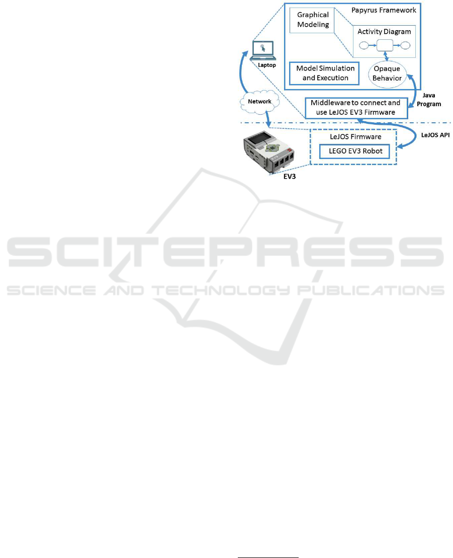
The figure 3 depicts the concretization of the con-
ceptual approach initially described in the figure 2. It
is visible from the figure 3 that the model-based con-
trol flow layered is based on the Papyrus framework,
which provides both (1) the modeling GUI and (2)
the model execution and simulation engine known as
Moka. We designed a UML activity diagram in pa-
pyrus modeler and then connected the model elements
to the opaque behaviors designed as plugins. The
opaque behavior follow the FUML semantics and en-
able the connection to the external tools (third party).
In the implementation part of the opaque behavior,
we created adaptors to connect to LeJOS firmware
(Lejos, 2015) which have been installed on Lego EV3
(EV3, 2013). LeJOS is an open-source java based op-
erating system (OS) for a Lego EV3 controller. There
are also other OS such as EV3Dev
1
but we chose
LeJOS as it was java based and provided remote APIs
to connect and control EV3.
Figure 3: Concrete Approach using Papyrus Framework
and Lego EV3 Robot.
5 EXPERIMENTATION
In this section, we implement our approach described
in section 4.2 by creating an experiment with a Lego
EV3 robot. A Lego EV3 might be a simplified exam-
ple of a CPS, but it useful in showing our approach
successfully and we can argue that the same approach
can be applied to more complex robots or multiple
heterogeneous robots. During our experimentation,
the models, the java based adaptors for LeJOS and the
model execution are all done using Eclipse Papyrus
framework.
5.1 Implementation: Lego EV3 Robot
5.1.1 Background
Firstly, we selected a Lego EV3 robot to implement
our approach for depicting a model-based execution
of a system as, (1) a Lego EV3 robot matches our
need to depict a system that can execute actuators and
sensors. (2) Lego EV3 is plug and play, not very ex-
pensive and can be easily build to depict different sce-
narios. (3) It has a strong community of users and de-
velopers along with the availability of various open-
source software. Additionally, it is important to men-
tion that Lego provides its own proprietary software
1
http://www.ev3dev.org/
Model-based Development of Modular Complex Systems for Accomplishing System Integration for Industry 4.0
491
tool called "Lego Mindstorms" based on LabVIEW
2
to build executable code for EV3 robot in a model-
driven manner. Moreover, Lego claims that the pro-
cess of using GUI based robot modeling technique
for modeling robot behaviour on their proprietary tool
is quite easy and intuitive. It is easy enough such
that a 10 year old can use it to build their own robot
(LEGO-Education, 2016). This reconfirms our point
that MDE is one of the good techniques available for
developing complex systems such as robots.
In contrast to the benefits, there are certain shortcom-
ings of the Lego Mindstorm software due to which we
can’t use it as such. These shortcomings are, (1) the
tool is proprietary and not open-source thus, we can-
not make changes to the APIs (2) it does not follow
any open standards (3) to the best of our knowledge,
the Lego Mindstorm software does not provide any
kind of standard API to control EV3 from external
tool (such as Papyrus framework) (4) the tool is used
to deploy the code directly on the EV3 (offline mode)
and doesn’t provide any mechanism to allow execu-
tion of EV3 from an executing model.
To tackle the above mentioned problem with Lego
proprietary software, we make use of an open-source
java based firmware for EV3 called LeJOS. We use
this tool for following reasons, (1) it provide connec-
tion to EV3 via its remote API using IP address (de-
picting the ideas of an IoT), (2) each actuator and sen-
sor can be controlled independently using the port id
and IP address.
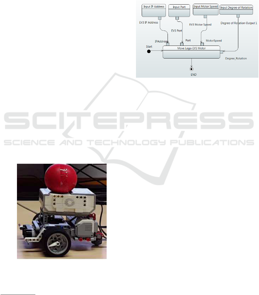
For our experimentation, we created a Lego
robotic car using two large motors (actuator) as shown
in the figure 4.
Figure 4: Lego EV3 Robotic Car.
2
http://www.ni.com/labview/
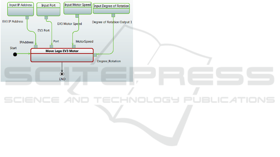
5.1.2 Setup
The figure 5 shows a behavior model (activity model)
having a behavior called "Move Lego EV3 Motor".
This activity has four input values. The input values
are used to providethe IP address of the robot, the port
of the actuator, the speed of the motor and the degree
of rotation for the robot (number of revolution).
Figure 5: Model showing the UML Activity Model to Move
the Car.
In order to execute the robotic Lego car, i.e. to
make it move in the physical world, we execute the
behaviour model by making use of the FUML based
Moka engine. This is achieved by creating an opaque
behavior called "RotateEV3MotorExecution". This
behavior extends "OpaqueBehaviorExecution" and
connects to the remote APIs of the LeJOS to control
and move the EV3 robot car. These opaque behav-
iors are reusable and can be used for any number of
separate models by providing different values for in-
put variables. In our case, the input values needed to
move the robot are, the IP address, port, motor speed
and the degree of rotation.
When the model is executed, it calls the above
mentioned opaque behavior and then passes the con-
trol to the adaptor created for the robot. The java
based adaptor in-return calls the LeJOS APIs and pro-
vide the incoming input values of the model to the
firmware. The LeJOS firmware on the EV3 robot gets
these values and executes the command to move the
actuator. As a note, Lego EV3 also has sensors for
data collection such as, color sensor, ultrasound sen-
sor but to keep our experiment simple we do not make
use any sensor data in this current work.
5.1.3 Model-based Execution
The figure 6 shows the execution of the UML be-
havior model (activity model) using FUML based Pa-
pyrus Moka engine. In the Papyrus framework, when
a model element has been executed (completed) the
MODELSWARD 2017 - 5th International Conference on Model-Driven Engineering and Software Development
492
color of the element changes to green. While the red
color indicates that a model element is currently be-
ing executed. While executing the model, Moka will
pass the input values to the underlying opaque behav-
ior and the robot will start moving as explained in the
above section. In case, of any kind of problem with
the underlying robot such as, issues with connection
between robot and computer, the same model can still
be executed like a normal simulation without the ac-
tual physical executing of the underlying robot. The
error handling will displaying the error message to the
developers for rectifying the problems. For e.g., one
of such common error message is "connection refused
to host: 10.0.1.1", which occurs when there is a prob-
lem in the wired connection between the robot and the
laptop.
Figure 6: FUML based Model Execution.
5.2 Evaluation
In this section, we evaluate some of the use cases for
EV3 robot using our approach as follows:
(1) Changes to the Behavior Model
Description: In case of a new system requirement,
how beneficial is the model-based execution ap-
proach?
Experience: Firstly, this approach provides loose
coupling between the control flow and execution
code. Secondly, as the execution of the robot is based
on execution of the models via API calls, we can
argue that the changes to the system can be tackled
easily. For e.g., initially, we created the "EV3 car
movement" process to move the EV3 car only in the
forward direction. This process consisted of a single
activity "Go Front". But, when there was a need to
move the EV3 in backward direction, we created a
new task called "Go Back" and used the same opaque
behavior created before with different input values.
In our experience, the addition of the new task and
the update to the model was fast and simple, like a
drag and drop of the activity task and then addition of
the opaque behavior to it with different input values.
Thus, using our approach a behavior model can be
updated quickly along with the reuse of existing
opaque behavior(s), creating a flexible and easy to
reconfigure complex systems environment.
(2) Interchanging Similar EV3 Robots or Actua-
tors
Description: In case of a need to change or update a
EV3 controller or an actuator, how beneficial is this
approach to manage such changes?
Experience: Due to the separation between the model
execution (control flow) and the robot execution us-
ing API calls, it is easy to manage such a need. To
change a problematic EV3 with a new EV3, only the
IP address of the new EV3 needs to be updated in
the activity model. Similarly, to change or update the
EV3 actuator, only the port id needs to be updated in
the behaviour model. Thus, we can argue that using
model-based execution it is possible to create a plug-
and-play environment.
Likewise, as this approach uses standard API calls
of the robot via IP address, we can argue that this ap-
proach can help to realize an IoT environment.
6 DISCUSSIONS
The following points are noteworthy for model-based
developmentfor complex systems in context of Indus-
try 4.0:
(1) Model-based development of CPS provides
easy system integration due to the use of standard tool
and languages (UML). It helps in creation of an inter-
operable and "plug and play" type ecosystem. More-
over, MDE provides need based abstraction of a sys-
tem to various stake holders for different concerns.
It also provide traceability between the various view-
points leading to a better management. For example,
exchange of information between strategy level (man-
agement) and business process analysts view in con-
text of Industry 4.0.
(2) Model-based execution of CPS using standard
execution semantics such as FUML provides a possi-
bility to connect to different software’s and external
tool and perform co-simulation using the same mod-
els.
(3) "Virtual factory" which is a "digital replica" of
the physical factory is an important feature of Industry
4.0. The model-based execution techniques will help
to create and use common model that can be used (A)
in the virtual factory to do simulations and (B) the
same models will be updated or enriched with data
coming form the virtual factory to do an optimized ex-
Model-based Development of Modular Complex Systems for Accomplishing System Integration for Industry 4.0
493

ecution of the real machines in the physical world, i.e.
a shop floor. Thus, knowledge gained via simulations
performed in the virtual factories will be transferred
to the physical factories for saving real materials and
resources in the physical world.
(4) Various software and tool providers involved
in Industry 4.0 will continue to build their solutions
based on industry standards. The use of standards
would help to resolve the issues related to interop-
erability between different tools. Moreover, instead
of creating dedicated middlewares, the model-based
approach for co-simulation can help to integrate and
exchange data between the various systems.
(5) Model-based CPS execution benefits from
concepts such as, "separation of concerns" that will
provide abstraction to various layer of the system
(viewpoints) along with concepts of loose coupling.
Thus, in case of replacement of the old system with
a new one, there will be no need to redesign the be-
havior models from scratch. The same models can be
reused by creation new connection or adaptors to the
external tool. However, this seamless change would
only be possible provided the new system provides
all the functionality of the old system.
(6) Furthermore, model-based execution enhances
understandability of the exact state of execution of a
machine. MBSE provides another advantages, such
as, a strong community and standards based open-
source tools. This help to achieve "digital continu-
ity" wherein, a system model created in one stan-
dard is transformed into another standards (model-to-
model or model-to-text). In context of Industry 4.0,
this is beneficial as, an activity model can be trans-
formed into a business process modeling and notation
(BPMN) model and can be executed on a manufac-
turing execution system (MES) which executes ma-
chines on industrial shop floor.
6.1 Limitations
Our work is based on the assumption that the CPS
will expose standard API for communication. More-
over, we map or glue the functionality of the CPS via
APIs to the opaque behavior(s) created in the mod-
eling framework (based on FUML semantics). How-
ever, a system model cannot execute a functionality
which is not provided by the API of the CPS.
Initially, this work was done keeping industrial
robots in the mind that perform standard repetitive
tasks. This approach was not built in context of au-
tonomous robots. Furthermore, at this stage we did
not create a domain specific language (DSL) for our
approach, but as this approach is based on UML stan-
dards, it is possible to extend this work for creating a
DSL without much effort. Most importantly, the im-
plementation of this approach is tightly coupled to the
modeling and execution framework or tool, thus the
model execution would be effected by the limitation
and performance issues of the tools.
7 CONCLUSION AND FUTURE
WORK
Industry 4.0 presents great opportunities for the man-
ufacturing sector, but it also lays great challenges on
the development of complex industrial systems that
will realize the vision of the connected, flexible and
smart industry. In this paper, we discussed several of
those challenges, namely, horizontal and vertical inte-
gration, interoperability and modularity. These chal-
lenges can be tackled through the use of model-driven
engineering, mainly, for the description or design and
execution of the industrial cyber-physical processes
and robotic systems.
The main contribution of this paper is a concep-
tual model-based approach for modular complex sys-
tem development, which can be applied to indus-
trial cyber-physical systems. This approach treats the
model as the first-class citizen of system develop-
ment, since the model is used for (1) modeling and
simulation (the "digital world") and (2) actual exe-
cution of industrial processes and robots (the "real
world"). The model thus becomes the pivot for both
horizontal and vertical integration. The approach was
validated with an implementation based on Lego EV3
robot and the Papyrus modeling environment with
Moka as model execution engine. The outcome is an
overall approach where the actual industrial automa-
tion systems are piloted from abstract models, while
keeping interoperability intact thanks to the use of a
standard API to communicate with the physical sys-
tems and its components.
In the future, we plan to extend this work and per-
form co-simulation with heterogeneous robots such
as, "NAO" the the humanoid robot. We also plan
to experiment and refine the approach with industrial
robots such as, Kuka. Plus, we plan to explore the
working of this approach in a service-oriented model-
driven way.
REFERENCES
ALF (2013). Action Language For Foundational UML
(ALF), Version 1.0.1. http://www.omg.org/spec/ALF/
1.0.1/PDF.
MODELSWARD 2017 - 5th International Conference on Model-Driven Engineering and Software Development
494

Cadavid, J., Alférez, M., Gérard, S., and Tessier, P. (2015).
Conceiving the model-driven smart factory. In Pro-
ceedings of the 2015 International Conference on
Software and System Process, pages 72–76. ACM.
EV3 (2013). LEGO Mindstorms. https://www.lego.com/en-
us/mindstorms.
FUML (2013). Semantics Of A Foundational Subset
For Executable UML Models (FUML), Version 1.1.
http://www.omg.org/spec/FUML/1.1/PDF.
Gherardi, L. and Brugali, D. (2014). Modeling and
reusing robotic software architectures: the hyperflex
toolchain. In 2014 IEEE International Conference on
Robotics and Automation (ICRA), pages 6414–6420.
IEEE.
Guermazi, S., Tatibouet, J., Cuccuru, A., Seidewitz, E.,
Dhouib, S., and Gérard, S. (2015). Executable mod-
eling with fuml and alf in papyrus: Tooling and ex-
periments. In Proceedings of the 1st International
Workshop on Executable Modeling co-located with
ACM/IEEE 18th International Conference on Model
Driven Engineering Languages and Systems (MOD-
ELS 2015), Ottawa, Canada, September 27, 2015.,
pages 3–8.
Harrand, N., Fleurey, F., Morin, B., and Husa, K. E. (2016).
Thingml: a language and code generation framework
for heterogeneous targets. In Proceedings of the
ACM/IEEE 19th International Conference on Model
Driven Engineering Languages and Systems, pages
125–135. ACM.
Hermann, M., Pentek, T., and Otto, B. (2016). Design
principles for industrie 4.0 scenarios. In 2016 49th
Hawaii International Conference on System Sciences
(HICSS), pages 3928–3937. IEEE.
Inglés-Romero, J. F., Lotz, A., Chicote, C. V., and Schlegel,
C. (2013). Dealing with run-time variability in service
robotics: towards a dsl for non-functional properties.
arXiv preprint arXiv:1303.4296.
Kovalenko, O., Wimmer, M., Sabou, M., Lüder, A., Ekapu-
tra, F. J., and Biffl, S. (2015). Modeling automationml:
Semantic web technologies vs. model-driven engi-
neering. In 2015 IEEE 20th Conference on Emerging
Technologies & Factory Automation (ETFA), pages 1–
4. IEEE.
LEGO-Education (2016). LEGO for Education.
https://education.lego.com/en-au.
Lejos (2015). LEJOS - Java for LEGO Mindstorms.
http://www.lejos.org.
Moka (2016). Papyrus Moka. Eclipse Papyrus Framework,
http://git.eclipse.org/c/papyrus/org.eclipse.papyrus-
moka.git/.
OMG (2016). Object Management Group (OMG). http://
www.omg.org/.
Papyrus (2016). Eclipse Papyrus Framework. https://
eclipse.org/papyrus/.
Perseil, I., Pautet, L., Rolland, J.-F., Filali, M., Delanote,
D., Baelen, S. V., Joosen, W., Berbers, Y., Mallet,
F., Bertrand, D., Faucou, S., Zitouni, A., Boufaida,
M., Seinturier, L., Champeau, J., Abdoul, T., Feiler,
P. H., Mraidha, C., and Gérard, S. (2011). An effi-
cient modeling and execution framework for complex
systems development. In Proceedings of the 2011
16th IEEE International Conference on Engineering
of Complex Computer Systems, ICECCS ’11, pages
317–331, Washington, DC, USA. IEEE Computer So-
ciety.
PolarSys (2016). PolarSys-Open Source Solutions for Sys-
tems Engineering and Embedded Systems. Eclipse In-
dustry Working Group, http://www.polarsys.org/.
PSCS (2015). Precise Semantics Of UML Composite
Structures (PSCS), Version 1.0. http://www.omg.org/
spec/PSCS/1.0/PDF.
Rahman, M. A. A. and Mizukawa, M. (2013). Model-based
development and simulation for robotic systems with
sysml, simulink and simscape profiles. International
Journal of Advanced Robotic Systems, 10.
Romero-Garcés, A., Manso, L., Gutierez, M. A., Cintas,
R., and Bustos, P. (2013). Improving the lifecy-
cle of robotics components using domain-specific lan-
guages. arXiv preprint arXiv:1301.6022.
Schlegel, C., Lotz, A., Lutz, M., Stampfer, D., Inglés-
Romero, J. F., and Vicente-Chicote, C. (2015). Model-
driven software systems engineering in robotics: cov-
ering the complete life-cycle of a robot. it-Information
Technology, 57(2):85–98.
Steck, A., Lotz, A., and Schlegel, C. (2011). Model-
driven engineering and run-time model-usage in ser-
vice robotics. In ACM SIGPLAN Notices, volume 47,
pages 73–82. ACM.
Tatibouët, J., Cuccuru, A., Gérard, S., and Terrier, F. (2014).
Towards a systematic, tool-independent methodology
for defining the execution semantics of uml profiles
with fuml. In Model-Driven Engineering and Soft-
ware Development (MODELSWARD), 2014 2nd In-
ternational Conference on, pages 182–192. IEEE.
UML2.5 (2015). Unified Modeling Language (UML), Ver-
sion 2.5. http://www.omg.org/spec/UML/2.5/PDF.
Wieland, M., Leymann, F., Schäfer, M., Lucke, D., Con-
stantinescu, C., and Westkämper, E. (2010). Using
context-aware workflows for failure management in a
smart factory. In Proc. of the Fourth Intl. Conf. on
Mobile Ubiquitous Computing, Systems, Services and
Technologies, pages 379–384.
Model-based Development of Modular Complex Systems for Accomplishing System Integration for Industry 4.0
495
