
Joint Depth and Alpha Matte Optimization via Stereo
Junlei Ma, Dianle Zhou, Chen Chen and Wei Wang
Department of Systems Engineering and Automation, National University of Defense Technology, Changsha,
Hunan, China
majunlei11@nudt.edu.cn
Keywords: Stereo matching, Automatic matting, Iterative optimization.
Abstract: This study presents a novel iterative algorithm of joint depth and alpha matte optimization via stereo
(JDMOS). This algorithm realizes simultaneous estimation of depth map and matting image to obtain final
convergence. The depth map provides depth information to realize automatic image matting, whereas the
border details generated from the image matting can refine the depth map in boundary areas. Compared with
monocular matting methods, another advantage offered by JDMOS is that the image matting process is
completely automatic, and the result is significantly more robust when depth information is introduced. The
major contribution of JDMOS is adding image matting information to the cost function, thereby refining the
depth map, especially in the scene boundary. Similarly, optimized disparity information is stitched into the
matting algorithm as prior knowledge to make the foreground–background segmentation more accurate.
Experimental results on Middlebury datasets demonstrate the effectiveness of JDMOS.
1 INTRODUCTION
Modern computer vision applications, such as novel
view generation or z-keying require high-quality
disparity maps. For these applications, producing
precisely delineated disparity borders (Matsuo et al.,
2015; Liu et al., 2014), which is traditionally
difficult in stereo matching, is specifically
important. In this study, we use the rich information
near boundaries in image mattes to refine the quality
of a depth map.
Image matting can be described as a labeling
problem of extracting the foreground object by
obtaining per-pixel opacity from its background.
Basically, an image is composed of a foreground I
and background B mixed with a certain degree of
opacity α, which can be defined as:
α
1
(1)
The image matting algorithm can segment the
foreground and background of an image. However,
Equation (1) is an ill-posed problem, because the
foreground F, background B, and opacity αare
unkonwn. Therefore, the existing matting algorithms
(Levin et al., 2008'; Chuang et al., 2001) require the
user to first label the foreground from the
background as additional constraints, which make
the matte quality deeply influenced by labeling
processing. As shown in Figure 1(b), if the
foreground and background specified by user is not
comprehensive, the quality of matting result will be
greatly degrade,compared with the red box in Figure
1(c). Figure 1(d) represents the trimap and its
resulting opacity (Figure 1(e)) accurately.
Image matting can be considered as a coarse
estimation of depth. Therefore, using depth is a
natural way to bootstrap the process and
automatically generate the trimap for image matting
(Singaraju et al., 2011). The image depth can also
provide new information for image matting to
improve its accuracy when implementing multi-layer
matting. It is a natural way to combine stereo
matching algorithm and image matting algorithm to
optimize each other iteratively.
The two major contributions of this study are:
fusing of depth and color information to obtain high-
quality fine-edge detail in the matting map and free
user interaction in the matting process. The
remainder of this paper is organized as follows.
Section 2 is a brief summary of the state-of-the-art
stereo matching and image matting algorithms. In
Section 3, the algorithm framework of disparity and
image matting is described, which consists of two
426
Ma, J., Zhou, D., Chen, C. and Wang, W.
Joint Depth and Alpha Matte Optimization via Stereo.
DOI: 10.5220/0006191304260433
In Proceedings of the 6th International Conference on Pattern Recognition Applications and Methods (ICPRAM 2017), pages 426-433
ISBN: 978-989-758-222-6
Copyright
c
2017 by SCITEPRESS – Science and Technology Publications, Lda. All rights reserved
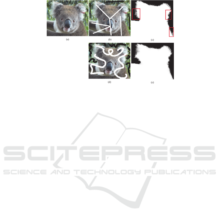
Figure 1: Human–computer interaction-based image matting. Image (a) is the original input. Image (b) is a trimap provided
by users. The resulting opacity diagram of image (c) has too much noise based on image (b). Figure (d) provides another
trimap by a user. Clearly, the opacity of image (e) obtained by the trimap of image (d) is more accurate.
steps: initialization and iterative optimization. We
adopt a local stereo matching algorithm to generate
the depth map via the opacity information. The
algorithm proposed by Levin (Levin et al., 2008) is
used to solve the opacity. Subsequently, we filter it
with the disparity value. The experimental results in
Section 4 show that the proposed algorithm is
effective in disparity and image matting. A brief
summary of the study and future research work are
presented in Section 5.
2 RELATED WORKS
Most stereo vision disparity map algorithms have
been implemented using multistage techniques.
These techniques, as codified by Scharstein and
Szeliski, consist of four main steps: matching cost
computation, cost aggregation, disparity selection,
and disparity refinement (Scharstein and Szeliski,
2002). Generally, stereo vision disparity map
algorithms can be classified into local and global
approaches (Hamzah et al., 2016). Local algorithms
usually calculate the matching cost for a given point
based on the window. Examples of implementation
of such methods are provided by the work of
Mattoccia et al. (Mattoccia et al., 2010), Arranz et
al. (Arranz et al., 2012), Xu et al. (Xu et al., 2013),
and Chen et al. (Chen et al., 2015). A representative
global algorithm is the stereo matching technique via
graph cuts, proposed by Boykov et al. (Boykov et al.,
2001).
For the problem of image matting, the existing
algorithms require the user to provide a trimap as
input to distinguish the foreground and background
regions. The most widely used algorithm is the
Bayesian model (Chuang et al., 2001), which
transforms the matting problem into a maximum a
posteriori, given the color of each pixel on the
current image, and computes the maximum possible
values of the foreground, background, and alpha.
Wang et al. used the belief propagation to expand
the local area of the sample points (Wang et al.,
2007). Based on the color linear assumption, Levin
et al. proposed a quadratic optimization function but
only included opacity (Levin et al., 2008). Although
the existing algorithms have contributed good
results, most of them need interaction with the user.
Combining stereo matching and image matting
algorithms can avoid user interaction. Researchers
have been doing this method for a decade (Baker et
al., 1998; Szeliski et al., 1998); however, the process
of combining the two algorithms has a slow
progress. For example, Zitnick et al. first computed
the disparity map, and then used the matting
algorithm according to disparity boundaries (Zitnick
et al., 2004). This method relies heavily on the
quality of the disparity map. Once the disparity map
boundary is extracted incorrectly, this method
cannot achieve the desired effect. In this study, we
propose the joint depth and alpha matte optimization
via stereo (JDMOS) algorithm. We do not need
accurate disparity map at initialization, but only
several foreground and background areas to generate
the initial matting. During the iteration, the boundary
details of objects in the disparity map are enhanced
by combining the matting information.
Consequently, the trimap region is enlarged
gradually through the optimized disparity map to
obtain higher quality matting.
Joint Depth and Alpha Matte Optimization via Stereo
427
3 ALGORITHM
Generally, without the loss, the algorithm uses the
left and right images as input. These images are
assumed to be rectified; thus, correspondences lie on
the same horizontal scan line. Our method provides
a depth map and matting information as output.
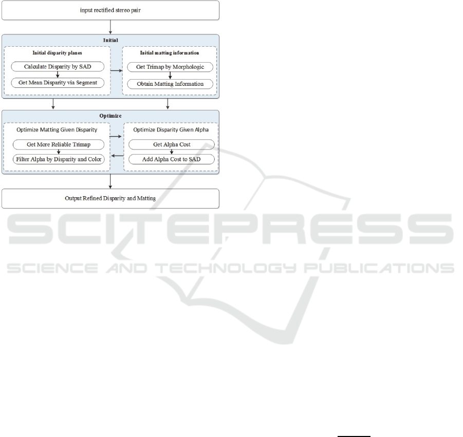
Figure 2: Overview of JDMOS.
As shown in Figure 2, JDMOS has two main
phases: an initialization phase, in which an initial
matte is extracted from a coarse depth; and an
iterative optimization phase, in which the matte and
depth are refined. In the initialization phase, the
initial depth map is first generated by combining the
sum of absolute differences (Tippetts et al., 2011)
and the graph cut algorithm. Then, the trimap is
obtained via the disparity map, and the initial
opacity is calculated according to the method
proposed by Levin et al. (Levin et al., 2008). During
the iterative optimization stage, the opacity
information of the left and right images is first added
to the cost aggregation function to enhance the
disparity map, especially the boundary region. The
enhanced depth map is then used to provide a more
reliable trimap for the matting, and the opacity is
bilaterally filtered using disparity and color
information. The entire optimization process is
iterated until satisfactory results are obtained.
3.1 Initialization
3.1.1 Initial Disparity
First, we use the improved SAD algorithm as the
cost aggregate function. The cost function is used to
calculate the color distance cost C
. The gradient
distance cost C
in the window of the size
2
1
21
for each disparity values belongs
to D
1,2,…,
, where
represents the
maximum disparity ranges:
,,
|
,
,
|
(2)
,,
|
,
,
|
(3)
where x and y respectively represent the horizontal
and vertical coordinates of the center point p of the
window, d∈D; I
and I
represent the
corresponding pixel values of the left and right
images, respectively.
and
represent the
gradient values at the corresponding points of the
left and right images, respectively. Combining the
color and gradient matching cost functions, we
obtain the following:
,,
,,
,,
(4)
where
λ
is the weight that balances the effect of
color and gradient information on matching costs.
Experientially,
λ
can be a small value.
Second, we use winner-take-all to select the
optimal disparity value
d
of the pixel p; the formula
is defined as follows:
min
∈
,,
.
(5)
Finally, we use the graph cut algorithm to
segment the target image, and we obtain a series of
segments
SS
,S
,⋯,S
,⋯,S
. The average
disparity value of each pixel in the
S
is calculated as
the final parallax value of the segmentation plane to
remove the noise of the disparity map and enhance
the disparity plane:
∑
∈
|
|
(6)
where
|
|
is the number of pixels in the segment
.
3.1.2 Initial Matte
As shown in Figure 3, a watershed algorithm is used
to divide a given depth map, binaries the segmented
disparity map into foreground and background
ICPRAM 2017 - 6th International Conference on Pattern Recognition Applications and Methods
428
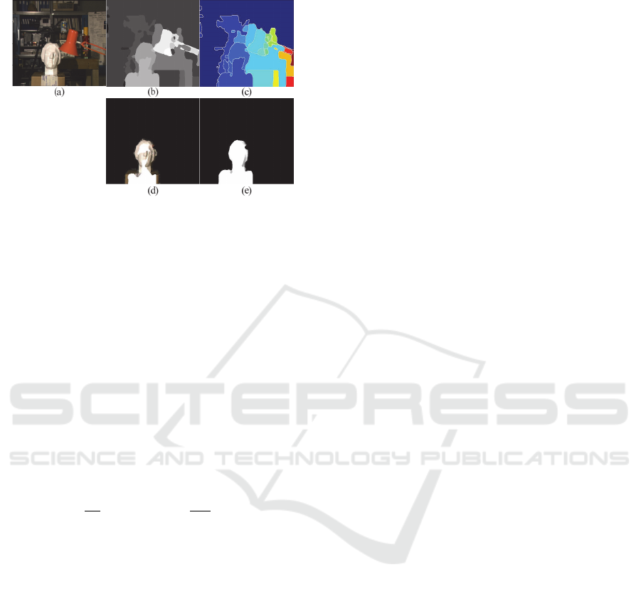
according to the specified threshold value, then
erode the foreground and background, and dilate the
Figure 3: Initial matte. (a) Input image; (b) initialized
disparity map; (c) segmentation of the initial disparity map
using the watershed algorithm; (d) the trimap
automatically generated by the erosion of foreground,
background, and dilation of unknown regions; (e)
initializing the opacity.
unknown region to generate trimap automatically.
According to the method proposed by Levin et al.,
the basic idea is to eliminate F and B in Equation (1)
based on the assumption of color linearity and
obtains a quadratic optimization function (Levin,
2008):
min
,
(7)
where L is the matting laplacian, which i,j
entry
is
,
1
|
|
1
|
|
,
∈
(8)
Here,
is the Kronecker delta,
is a 31
vector of the RGB for pixel in window
,
is a
31 mean vector of the colors in a windows
,
∑
is a 33 covariance matrix, |
| is the number of
pixels in this window, and
is the 33 identity
matrix.
3.2 Optimization
In this section, we apply a two-step procedure. First,
given the opacity, add the opacity consistency of the
left and right images to the cost aggregation function
to enhance the disparity map. Second, given the
optimized disparity map, obtain more reliable trimap
and filter opacity to refine mattes. These two steps
are iterated, and results show that the proposed
algorithm can achieve satisfactory results with only
two to three iterative steps.
3.2.1 Optimize Disparity Plane
The opacity information of the left and right images
is obtained. Subsequently, similar method is applied
in the window of size
2n1
2n1 for each
disparity value that belongs toD1,2,⋯,d
,
where d
represents the maximum parallax range.
We use C
to measure the matching cost of the left
and right opacities:
,,
|
,
,
|
(9)
where α
and α
represent the opacity of the
corresponding pixel of the left and right images,
respectively.
C
is added to Equation (4); then, the optimized
cost aggregation function C
is obtained as follows:
,,
C
,,
,,
(10)
where ξ is the balance parameters.
3.2.2 Optimize Matte
Given the optimized disparity map, we use the
watershed segmentation. When generating the
trimap, we can narrow the uncertain region by
reducing the erode/dilation band size around 2–4
pixels.
The disparity value is added as the 4th channel
with the original R, G, and B channels for a color
image, and the
in Equation (8) is modified to
combine RGB with disparity D to fully utilize the
optimized disparity information and enhance the
matting effect (Zhu et al., 2009).
Although Zhu et al. added weight to the disparity
value (Zhu et al., 2009); the basic assumptions of
Levin et al. regarding color linear assumption are
disproved. Figure 4(c) shows the RGB value
distribution of all the pixels in a small window and
verifies the correctness of the color linearity
assumption. Figures 4(d), 4(e), and 4(f) can be used
as the projection of the RGBD values of all the
pixels in the small window on R, G, and B and show
that the values of the pixels in a small window do
not lie on a single line in the RGBD space,
especially at the boundaries of the disparity
variation.
Joint Depth and Alpha Matte Optimization via Stereo
429
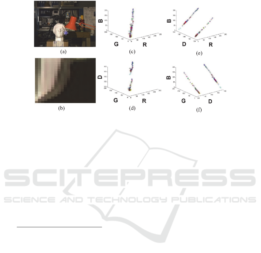
Figure 4: Distribution of pixels within a small window: (a) Original image; (b) a small window selected from image (a); (c)
distribution of the RGB distribution of all the pixels in window (b); (d) distribution of the RGD of all the pixels in window
(b); (e) distribution of the RBD values for all the pixels in window (b); (f) distribution of the GBD values for all the pixels
in windows (b). Images (c), (d), (e), and (f) can also be viewed as the projections of the RGBD values of all the pixels in
window (b) on D, B, G, and R, respectively.
Therefore, we propose a method to weigh the
opacity obtained via the method (Levin et al., 2008)
using the disparity and color information. Evidently,
if the disparity values of the two pixels are
significantly different, then these are likely to belong
to different layers and the weight becomes smaller.
If the colors of the two pixels are similar, the weight
value will increase accordingly. After filtering, the
opacity of pixel i become:
∑
,
∙
,
∙
∈
∑
,
∙
,
∈
(11)
where W
and W
denote the weights of color and
disparity distances, respectively, which are defined
as follows:
,
(12)
,
(13)
where w
and w
are used to adjust the weight of
the color and distance of disparity value,
respectively.
4 EXPERIMENTS
We evaluate JDMOS using the Middlebury dataset.
The parameters in Equations (4) and (10) are set to
the constant values of λ0.8 and ξ0.5. With
CPU at 2.00 GHz, it takes approximately 20 s to
process an image size of 384288 averagely.
4.1 Optimized Result
By applying the methods in the initialization and
optimization phases, we compare the disparity map
and matting before and after optimization. The
experimental results on Tsukuba are shown in Figure
5. On the initial depth map (e), several abnormal
points (black holes) are present on the left side of the
paper box, and several noise spots appear in the
initial mattes (c). After two iterations, the depth map
(f) is enhanced at the boundaries because of the
increase in matting information. Similarly, since the
depth of information is incorporated into the image
matting algorithm, mattes (b) have also been
significantly improved in the foreground and
background layers. The entire experiment process is
automated without human interaction. More results
on Kid are shown in Figure 6.
ICPRAM 2017 - 6th International Conference on Pattern Recognition Applications and Methods
430
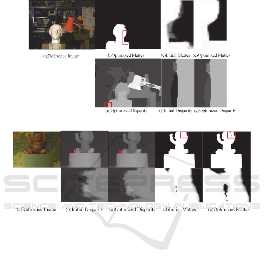
Figure 5: Experiment results of the algorithm on the Tsukuba image.
Figure 6: More results from the Kid image.
4.2 Algorithm Robustness
We compare the method proposed by Levin (Levin,
2008) as manual matting with JDMOS. As shown in
Figure 7, manual matting has poor performance in
some cases, in which the input of the user's input is
not representative. Conversely, our algorithm is
relatively robust.
The quality of the manual matting is heavily
dependent on the input of the user. Figures 7(a) and
7(e) are two different user inputs. The information
provided in Figure 7(e) is more comprehensive,
making the result more accurate, as shown in Figure
7(f). For Figure 6(a), the area between the face and
arm of the baby is only a few pixels away (Figure
7(a) at the red frame). Marking a certain background
information between them is difficult for the user.
Therefore, neither of the two types of manual
matting distinguishes the area correctly, as shown in
Figures 7(d) and 7(h). In contrast, our algorithm
does not rely on human manipulation, thereby
resulting in more robust image matting; Figure 7(n)
further proves that the proposed algorithm can solve
the problem mentioned above by integrating the
disparity information into the image matting based
on the ground truth.
5 CONCLUSION
In this study, given the complementary nature of
alpha matte and depth, an iterative feedback method
is presented to enhance their quality mutually.
Joint Depth and Alpha Matte Optimization via Stereo
431
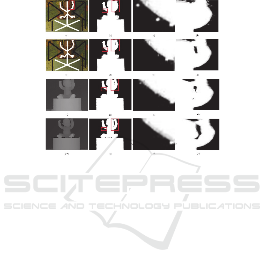
Figure 7: Comparison among JDMOS, manual matting, and matting via ground truth. Image (a) is a user input; (b) is the
opacity obtained by (a) as a trimap; (c) and (d) are enlarged views of the red frame in (b); (e) is another user input; (f) is the
opacity obtained by (e) as a trimap; (g) and (h) are enlarged views of the red frame in (f); (i) is the disparity map after
optimization; (j) is the opacity obtained via (i); (k) and (l) are enlarged views of the red box in (j); (m) is the ground truth;
(n) is the opacity obtained by (m); and (o) and (p) are enlarged views of the red box in (n).
Compared with manual matting, our proposed
algorithm is free from human interaction, which
avoids uncertainty generated from user operations
and can handle what humans cannot address. For
example, the area between foreground and
background is extremely narrow that users cannot
mark on it. Experiments show that JDMOS is robust
to a few difficult situations and can reduce the error
of the disparity map and improve the accuracy of the
image matting.
The matting problem is under-constrained and
intrinsically difficult. JDMOS has made some
important advancement in this problem; however,
one limitation remains to be addressed. The quality
of the result is partly dependent on the quality of the
initial depth map.
In the following study, we will focus on the
improvement of the optimization function. We
expect to combine binocular stereo matching with
the image matting algorithm using only one energy
optimization function to fuse the two information
more closely. Also, we are interested in editing
multiple regions in an image.
REFERENCES
A. Levin, D. Lischinski, and Y.Weiss.2008. A closed form
solution to natural image matting. IEEE Trans. on
PAMI, 30(2): 228–242.
Y. Chuang, B. Curless, D.Salesin, and R.Szeliski. 2001. A
Bayesian approach to digital matting. In CVPR (2),
pages 264–271, 2001.
D. Scharstein and R. Szeliski, 2002. A taxonomy and
evaluation of dense two-frame stereo correspondence
algorithms. International Journal of Computer Vision,
vol. 47, no. 1–3, pp.7–42.
S. Mattoccia, S. Giardino, and A. Gambini, 2010.
Accurate and efficient cost aggregation strategy for
stereo correspondence based on approximated joint
bilateral filtering,” in Proceedings of the Asian
Conference on Computer Vision (ACCV ’10), vol. 38,
pp. 371–380, Xi’an, China.
L. Xu, O. C. Au, W. Sun et al., 2013. Stereo matching by
adaptive weighting selection based cost aggregation.
in Proceedings of the IEEE International Symposium
on Circuits and Systems (ISCAS’13), pp.1420–1423,
Beijing, China.
ICPRAM 2017 - 6th International Conference on Pattern Recognition Applications and Methods
432

A. Arranz, A. S´anchez, and M. Alvar. 2012. Multi
resolution energy minimisation framework for stereo
matching. IET Computer Vision, vol. 6, no. 5, pp.
425–434.
Y. Boykov, O. Veksler, R. Zabin. 2001. Fast Approximate
Energy Minimization via Graph Cuts [J], IEEE Trans.
on PAMI, 23(1):1222-1239.
J. Wang and M. Cohen. 2007. Simultaneous matting and
compositing. In CVPR.
S. Baker, R. Szeliski, and P. Anandan. 1998. A layered
approach to stereo reconstruction. In CVPR, pages
434–441.
R. Szeliski and P. Golland. 1998. Stereo matching with
transparency and matting. In ICCV, pages 517–525.
L. Zitnick, S. Kang, M. Uyttendaele, S. Winder, and R.
Szeliski. 2004. High-quality video view interpolation
using a layered representation. ACM Transaction on
Graphics, 23(3):600–608.
Ruigang Yang, Jiejie Zhu, Miao Liao, Zhigeng Pan. 2013.
Joint depth and alpha matte optimization via fusion of
stereo and time-of-flight sensor. IEEE Conference on
Computer Vision and Pattern Recognition, vol. 00, no.
, pp. 453-460, 2009,
T. Matsuo, S. Fujita, N. Fukushima, and Y. Ishibashi.
2015. Efficient edge-awareness propagation via
single-map filtering for edge-preserving stereo
matching, in Three-Dimensional Image Processing,
Measurement (3DIPM), and Applications, vol. 9393 of
Proceedings of SPIE, International Society for Optics
and Photonics, San Francisco, Calif, USA.
J. Liu, X. Sang, C. Jia, N. Guo, Y. Liu, and G. Shi. 2014.
Efficient stereo matching algorithm with edge-
detecting, in Optoelectronic Imaging and Multimedia
Technology III, vol. 9273 of Proceedings of SPIE, p.
7.
B. J. Tippetts, D.-J. Lee, J. K. Archibald, and K. D.
Lillywhite. 2011. Dense disparity real-time stereo
vision algorithm for resource limited systems, IEEE
Transactions on Circuits and Systems for Video
Technology, vol. 21, no. 10, pp. 1547–1555.
D. Chen, M. Ardabilian, and L. Chen. 2015. A fast
trilateral filter based adaptive support weight method
for stereo matching, IEEE Transactions on Circuits
and Systems for Video Technology, vol. 25, no. 5, pp.
730–743.
Rostam Affendi Hamzah and Haidi Ibrahim. 2016.
Literature Survey on Stereo Vision Disparity Map
Algorithms. Journal of Sensors, vol. 2016, Article ID
8742920, 23 pages, doi:10.1155/2016/8742920.
Dheeraj Singaraju, Rene Vidal. 2011. Estimation of Alpha
Mattes for Multiple Image Layers, IEEE Transactions
on Pattern Analysis and Machine Intelligence, v.33
n.7, p.1295-130
Joint Depth and Alpha Matte Optimization via Stereo
433
