
DWT based Low Power Image Compressor for Wireless Capsule
Endoscopy
Kushaagra Goyal, Abhishek Lal and Basabi Bhaumik
Department of Electrical Engineering, Indian Institute of Technology Delhi, Hauz Khas, New Delhi 110016, India
Keywords:
Wireless Capsule Endoscopy, Low Power, Discrete Wavelet Transform, Serialiser.
Abstract:
In WCE literature so far, the stress is on having an image compressor with low power consumption and silicon
area. However one needs to consider the image compressor along with the serialiser, the interface between
image compressor and transmitter as a single unit. In this paper, we propose the design of a hardware efficient,
low power image compression system along with the serialiser for wireless capsule endoscopy. It is based on
integer version of discrete wavelet transform and uses low complexity encoders like adaptive Golomb-Rice
encoder. An alternative architecture for serialiser is proposed specific to the algorithm which runs at only 8
times instead of 32 times the frequency required at the existing compressors in the literature. The proposed
algorithm gives a compression of 91.88 percent at a PSNR of 38.17. The implementation of the compressor
plus serialiser in 130nm HS (high speed) standard CMOS process technology consumes 16.9uW of power at
2 frames per second for 256×256 image. Compared to the existing designs at similar power consumption,
the proposed scheme reduces the serialiser’s frequency by a factor of four besides giving at least 1.5 % higher
compression.
1 INTRODUCTION
Wireless Capsule endoscopy uses a miniature camera
to capture images of the gastrointestinal tract. The
whole system is built into a small capsule for min-
imum invasiveness. The patient ingests a small vi-
tamin size capsule containing CMOS image sensor
array, LEDs, battery, and an RF transmitter. It cap-
tures images and sends them to an outside workstation
where the images can be analysed by gastroentolo-
gists. The battery for the capsules runs for about 8-10
hours. A major research thrust is on incorporating ad-
ditional functionalities like drug delivery and locomo-
tion on to the chip (Bruaene et al., 2015; Koulaouzidis
and Iakovidis, 2015; Hale et al., 2014). Introduc-
ing these new features reduces the capsule area de-
voted to the power source, thereby necessitating a
decrease in power consumption to lengthen the cap-
sule lifetime. In this paper we focus on designing
a low power image compressor along with its inter-
face to the transmitter. Our scheme employs hard-
ware efficient and low complexity methods like inte-
ger discrete wavelet transform (Bhanu and Chilam-
buchelvan, 2012) and adaptive Golomb-Rice encoder
(Memon, 1998). We also propose a new architecture
for the serialiser which works at 8 times the frequency
of the compressor.
The prior works which are based on DCT (Dis-
crete Cosine Transform) divide the image into non
overlapping blocks and employ transforms to reduce
2D spatial redundancy in an image. Since the im-
age comes in raster-scan fashion, the above technique
necessitates the use of memory for storing few rows
of incoming image. The computational resources re-
quired to compute these transforms are also high. As
a result they are not hardware efficient and consume
lot of power. A low memory DPCM (Differential
Pulse Code Modulation) based design was proposed
in (Khan and Wahid, 2013; Khan and Wahid, 2011a).
It used hardware efficient techniques at the cost of
low compression rates. Recently, in (Fante et al.,
2016), an image compression scheme was proposed
which was based on optimal combination of quantisa-
tion and subsampling thereby achieving higher com-
pression rate as compared to the previously proposed
schemes (Khan and Wahid, 2013; Khan and Wahid,
2011a). However, the serialiser, which runs at 32
times the compressor frequency is the major power
consumer and the existing designs did not optimise
its power consumption.
In this paper, we treat compressor and serialiser
as a unit and propose a new architecture for the
Goyal K., Lal A. and Bhaumik B.
DWT based Low Power Image Compressor for Wireless Capsule Endoscopy.
DOI: 10.5220/0006103000170024
In Proceedings of the 10th International Joint Conference on Biomedical Engineering Systems and Technologies (BIOSTEC 2017), pages 17-24
ISBN: 978-989-758-216-5
Copyright
c
2017 by SCITEPRESS – Science and Technology Publications, Lda. All rights reserved
17
serialiser which works at 8 times the frequency of
the compressor. Furthermore, we employ 1D DWT
(Discrete Wavelet Transform) instead of subsampling
for achieving higher compression while maintaining
good image quality. Although using 2D DWT would
have increased the compression, it would have sub-
stantially increased the hardware requirements. Using
1D DWT keeps the hardware minimal and increases
the compression with good image quality.
This paper is organised as follows – a detailed dis-
cussion of the proposed algorithm is given in section
2, performance results are described in section 3, sec-
tion 4 gives details about the hardware realisation and
the power consumption. Finally in section 5 we con-
clude this paper.
2 PROPOSED ALGORITHM
The algorithms proposed by (Khan and Wahid, 2013)
and (Fante et al., 2016) are power efficient as they
minimize the usage of buffer memory while achiev-
ing a very high compression ratio. In this section
we will discuss the techniques employed to achieve
a better compression ratio along with reduced power
consumption. The compression algorithm used takes
hardware feasibility into account. We have ensured
that the average and minimum PSNR (Peak signal-to-
noise ratio) is over the recommended value (Cosman
et al., 1994; Philip et al., 2008). The algorithm is
designed such that the transmitter has to run at a fre-
quency which is only at 8 times higher than that of
the compressor. Our design reduces the serialiser fre-
quency by a factor of 4 as compared to the existing
designs((Khan and Wahid, 2011b) and (Fante et al.,
2016)). The block diagram of the image compressor
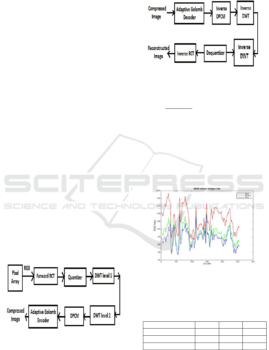
and decompressor is shown in the Figure 1 and 2 re-
spectively.
Figure 1: Block Diagram of Image Compressor.
2.1 Forward RCT Transform
RCT stands for reversible colour transform. The im-
age obtained from the camera is of RGB888 format.
Figure 2: Block Diagram of Image Decompressor.
It is first converted from RGB color space to YUV
color space using the following equations:
Y =
R + 2G + B
4
,U = R − G,V = G − B (1)
Figure 3 shows the R, G and B values of the pixels
along the middle row of an image. We see that the
Red, Green and Blue channels are highly correlated.
We also observe that red is the most dominant color as
compared to green and blue. Thus we can safely as-
sume that the signal which is the difference between
Green and Blue will contain very less information.
Therefore, we transformed the color space from RGB
to YUV to de-correlate the image (Fante et al., 2016).
Figure 3: R, G and B value of pixel along middle row.
Table 1 and 2 shows the correlation between dif-
ferent color channels. We can easily see that the cor-
relation in the transformed color space is reduced.
Table 1: Correlation between RGB components.
Correlation Matrix Red Green Blue
Red 1 0.9626 0.9159
Green 0.9626 1 0.9864
Blue 0.9159 0.9864 1
The Y component corresponds to intensity value
while U and V represents the chrominance compo-
nents. It should be noted that the value of Y varies
BIODEVICES 2017 - 10th International Conference on Biomedical Electronics and Devices
18
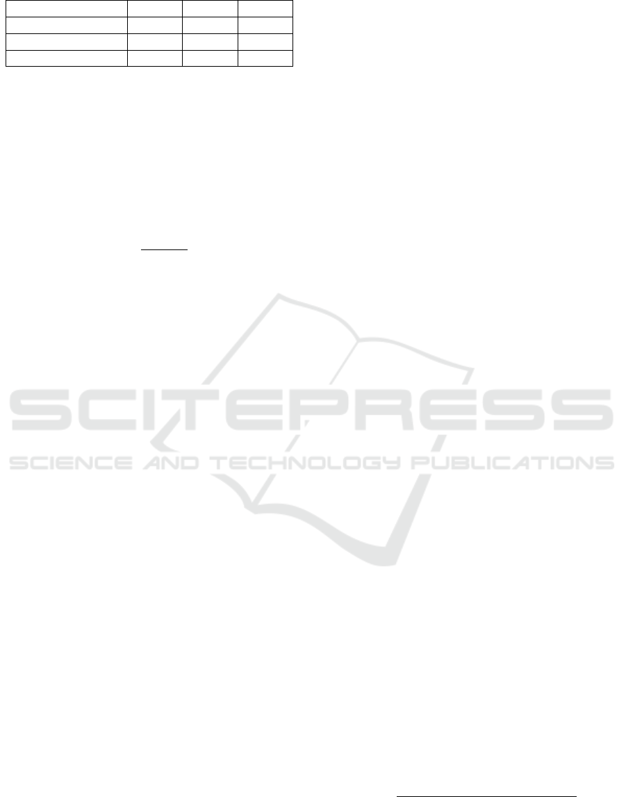
Table 2: Correlation between YUV components.
Correlation Matrix Y U V
Y 1 0.6814 0.6599
U 0.6814 1 0.8554
V 0.6599 0.8544 1
from 0 to 255 whereas the values of U and V varies
from -255 to 255.
2.2 Quantisation
The output of RCT forward transform is quantized
first – in order to implement a hardware efficient
quantization, we ignore the least significant bits. The
quantization formula used is:
P
q
=
P + Q/2
Q
(2)
Where P is the value of the pixel, Q is the quantisa-
tion value given by 2
l
where l is the number of bits
to be quantised and P
q
is the quantised pixel value.
In our design we quantized the YUV image by 3 bits.
Increasing it to 4 bits resulted in unacceptable PSNR
(Peak Signal to Noise Ratio) values while 2-bits quan-
tization reduced the compression ratio. Therefore 3
bits was the sweet spot in our design as shown in Sec-
tion 3.Quantization also reduces the standard devia-
tion of the data which will further helps us in adaptive
Golomb-Rice encoding.
2.3 DWT
The algorithm proposed by (Fante et al., 2016) sub-
samples the U and V component by 4 since U and
V contains less information compared to Y. In our
implementation,we have used the 5-3 integer DWT
to down-sample the data (Jing et al., 2008). The U
and V components are successively passed through
two DWT blocks while retaining the lower frequency
components at each stage. Since images of interest
are sparse at higher frequencies, our method achieves
compression comparable to the previously employed
subsampling approach while retaining a better image
quality. For hardware efficiency we implemented the
lifting architecture of 5-3 integer DWT (Bhanu and
Chilambuchelvan, 2012).
2.4 DPCM
DPCM exploits the spatial redundancy of an image.
It uses a prediction function which predicts the value
of a pixel given the previous values. In our design we
use the simplest prediction function i.e. the predicted
value is same as the previous value. Better results
could have been achieved by using better prediction
functions or using 2D prediction scheme at the cost
of higher hardware requirements.
2.5 Corner Clipper
While the lens of the capsule generates a circular im-
age, the image sensor is rectangular. Due to this all
pixels outside the circular region have a value of zero.
The Golomb Rice encoder would encode these pixels
by using a single bit for each component. As proposed
by (Khan and Wahid, 2011a), we use linear cropping
to crop these pixels. This process is hardware efficient
and increases the Compression Rate.
2.6 Golomb Encoder
Golomb Rice encoder was shown to be an hardware
efficient entropy encoder for endoscopy images. In
(Khan and Wahid, 2011a), Golomb Rice parameter
m = 2
k
was static but it gave poor compression. In
(Fante et al., 2016), this parameter changed on the
fly and was determined using a single context to re-
duce computational complexity. Using such an adap-
tive Golomb-Rice encoder improved the compression
rate. Both of these encoders produced maximum code
length of 32. This required the serialiser to work at 32
times the frequency which consumed a lot of power.
We investigated the effect of reducing the max code
length to 16 bit by limiting the parameter glimit to
16 in the Golomb Rice encoder. Doing this resulted
in the decrease in the Compression Rate(CR). But by
replacing subsampling by DWT in our algorithm, we
were able to achieve an extra bit of quantisation. This
helped in decreasing the max code length to 16 with-
out seriously affecting the Compression Rate.
Table 3 summarises the details of our encoders
in comparison to the ones proposed by (Khan and
Wahid, 2013) and (Fante et al., 2016).
3 PERFORMANCE EVALUATION
For evaluation purposes, 120 images were collected
from Gastrolab (Gastrolab, 2014). It includes the en-
tire GI tract and thus is a good representative for the
entire digestive system. The performance of the pro-
posed compression algorithm is evaluated using Com-
pression Rate(CR) which is given by:
CR =
1 −
Image Size After Compression
Image Size Before Compression
× 100
(3)
DWT based Low Power Image Compressor for Wireless Capsule Endoscopy
19
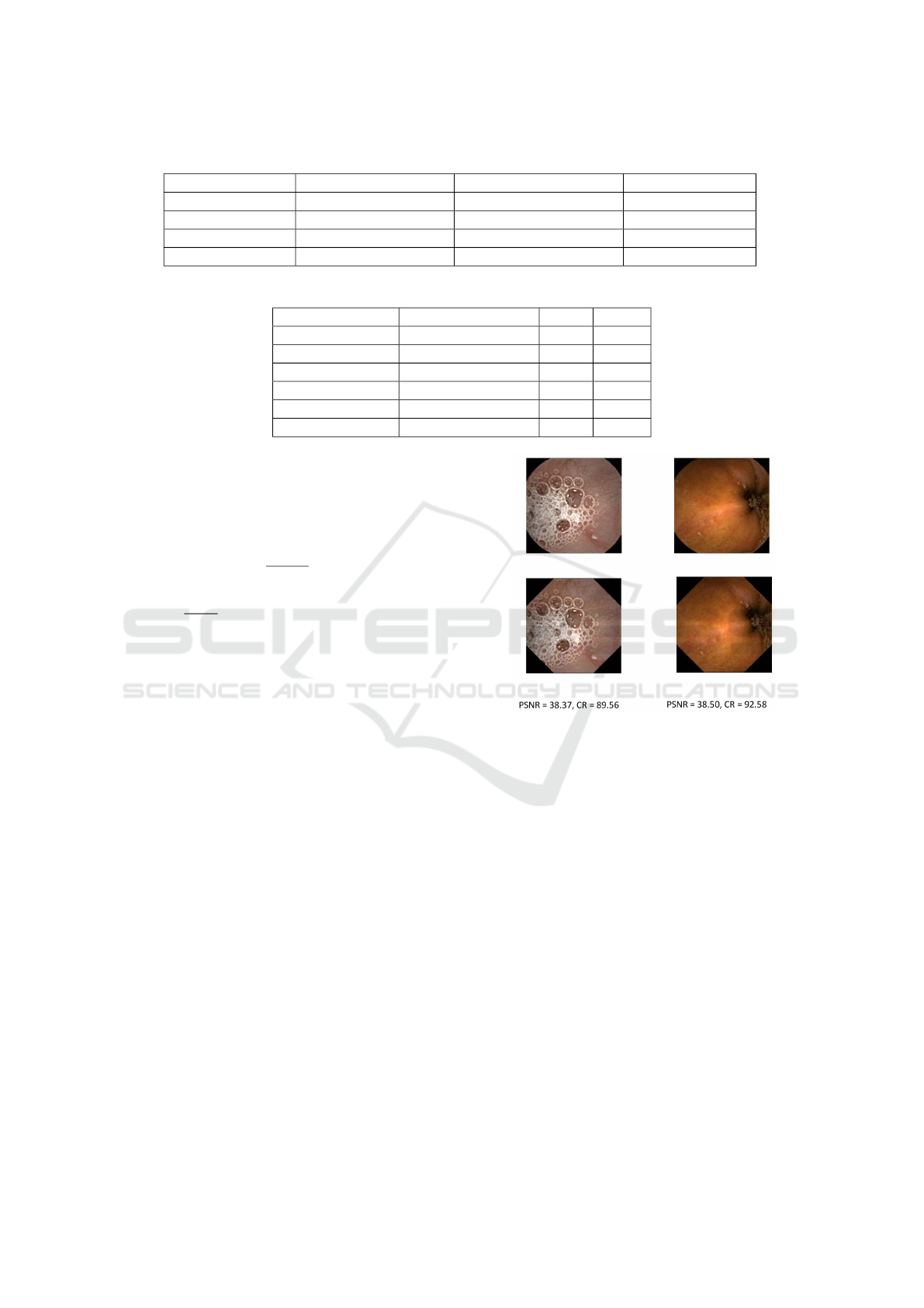
Table 3: Golomb Encoding Comparison Table.
Aspect Golomb (Proposed) Golomb (Fante) Golomb (Khan)
Parameter k Dynamically calulated Dynamically Calculated static
Max Code Length 16 32 32
Compression Medium Compression Medium Compression Low Compression
Complexity Medium Complexity Medium Complexity Low Complexity
Table 4: Performance of Algorithm for Different Parameters.
Quantisation Golomb-Encoder CR PSNR
Q = 1 Adaptive glimit=16 80.06 46.56
Q = 2 Adaptive glimit=16 84.99 44.49
Q = 4 Adaptive glimit=16 89.22 42.27
Q = 8 (Proposed) Adaptive glimit=16 91.88 38.17
Q = 8 Adaptive glimit=32 91.95 38.17
Q = 16 Adaptive glimit=16 93.38 32.87
The proposed image compression algorithm is
lossy due to quantisation and DWT where high fre-
quency components are dropped. The quality of the
reconstructed image is measured using PSNR which
is given by (Korhonen and Junyong, 2012) :
PSNR = 10 × log
10
MAX
2
MSE
(4a)
MSE =
1
3HW
k=3
∑
k=1
i=H
∑
i=1
j=W
∑
j=1
(I(i, j,k) − K(i, j,k))
2
(4b)
MAX is the maximum possible pixel value which is
255 in our case, as we are using 8 bits per sample. H
and W are the height and width of the original image I
and K represents the reconstructed noisy image. The
algorithm is tested for different values of quantisation
and different setting of Golomb encoder. The perfor-
mance under different settings is tabulated in Table 4.
From the Table 4, we observe that on increasing
quantisation, the compression rate increases but the
quality of the reconstructed image falls. An optimum
tradeoff between the achieved compression and the
image quality is achieved at Q = 8. Setting the maxi-
mum code length to 16 instead of 32 in Golomb Rice
encoder decreases the compression by only 0.07 per-
cent but decreases the power in the serialiser and al-
lows us to design an efficient architecture of the seri-
aliser which can run at 8 times the frequency of the
compressor. Thus in our proposed algorithm, we use
adaptive Golomb Rice encoder with max code length
set to 16 and are able to achieve compression of 91.88
percent at a PSNR of 38.17. In Table 5 we com-
pare the performance of our algorithm with the recent
existing works. Our implementation achieves higher
compression rate than the previous implementations.
Figure 4 shows two images compressed and recon-
structed using our algorithm.It can be seen that the
Figure 4: Original (top) and Reconstructed(bottom) images
with PSNR and CR value for 2 out of the 120 images.
reconstructed image quality is very good and it is al-
most indistinguishable from the original to the human
eye.
4 HARDWARE REALISATION
4.1 Image Compressor
The block diagram of the proposed architecture for
the image compressor is shown in Figure 5. The im-
age compressor has three inputs : 8 bit Pixel [7:0], Re-
set, and CLK. Its output includes a 16 bit code word,
code word length and a valid bit. The image com-
pressor accepts the input in RGB format and is used
to compress a 256*256 image with 24 bits per pixel
at 2 frames per second.
The control unit is the heart of the design and gen-
erates the control signals for the entire design. It takes
BIODEVICES 2017 - 10th International Conference on Biomedical Electronics and Devices
20
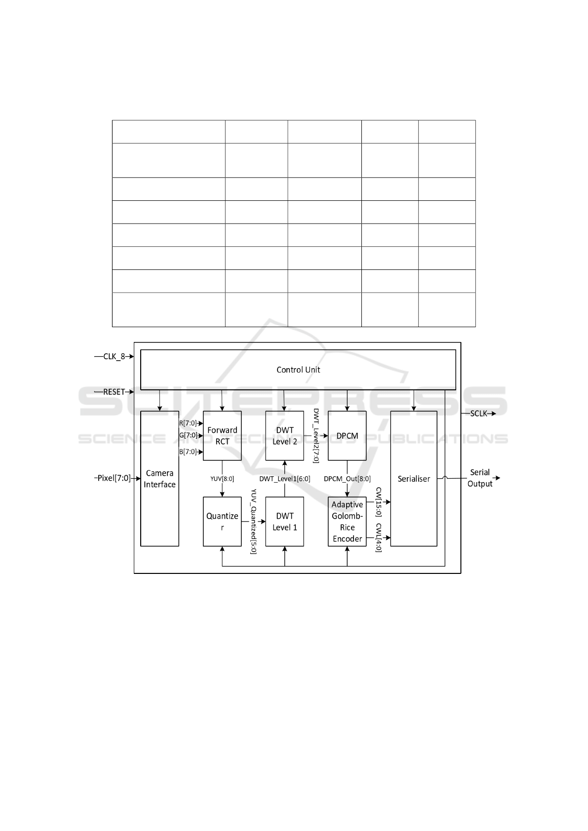
Table 5: Comparison with Previous Works. In this table, Q stands for quantisation, SS stands for sub-sampling , GR stands
for Golomb-Rice, RL stands for Run Length.
Method Colour
Space
Entropy
Encoder
CR PSNR
DPCM + Q + SS (Fante
et al., 2016)
YUV Adaptive GR
with code limit
= 32
90.35 40.66
DPCM (Khan and
Wahid, 2011a)
YUV Static GR 76.64 52.60
DPCM + SS (Khan and
Wahid, 2011b)
YUV 812 Static GR 82.57 41.01
DPCM + SS (Khan and
Wahid, 2012)
YUV 16:1:1 Static GR,
code limit=32
85.72 38.37
DCT (Turcza and
Duplaga, 2011)
YC
g
C
o
Huffman 91.34 36.67
DCT (Turcza and
Duplaga, 2013)
YC
g
C
o
GR with RL 91.35 38.59
DPCM + Q + DWT (This
Work)
YUV Adaptive GR
with code limit
= 16
91.88 38.17
Figure 5: Hardware Architecture of Image Compressor.
CLK and reset as input and generates two separate
clocks for the compressor and serialiser. Moreover,
it contains a column and a row counter which keeps
track of the current pixel being processed and also
helps in corner clipping. It further generates the “valid
signal” which signifies whether the current output is
valid or not. The pixels is encoded using quantisation,
DWT transform and Golomb encoding.
The forward RCT module is a purely combina-
tional block and performs colour space transforma-
tion from RGB to YUV space. The quantiser per-
forms the 3 bit quantisation on the output of the RCT
module. 2 level 1D DWT is used on the quantized U
and V values. Lifting architecture is used to imple-
ment the 5-3 integer wavelet. The output is encoded
using simple DPCM and passed through Golomb en-
coder. The Golomb encoder involved mapping neg-
ative values to positive values, finding parameter k
DWT based Low Power Image Compressor for Wireless Capsule Endoscopy
21
using context variables and encoding the given pixel.
It produces a 16 bit code word along with the code
word length which is fed to the serialiser. The entire
design is hardware efficient and uses simple computa-
tions along with no buffer memory. Small sets of reg-
isters are used in RGB, DWT , DPCM and Golomb
encoder. In total, 229 registers are used in the design
of the compressor. The image compressor processes
each pixel in 3 cycles and thus for a 256*256 image
at 2fps requires a clock frequency of 393.216 KHz.
4.2 Serialiser
The Serialiser proposed by (Fante et al., 2016) and
(Khan and Wahid, 2013) works at 32 times the fre-
quency of the compressor. It was also mentioned that
the serialiser was a major power hog. In order to re-
duce the consumption of power, first of all we limited
the input to the serialiser to 16 bit code by changing
the Golomb encoder in the compressor. Secondly, in
our algorithm we were effectively sub-sampling the
U and V components by 4. This implied that for ev-
ery 12 clock cycles of the compressor, we sent 4 Y
values, 1 U value and 1 V value, whereas in 6 clock
cycles no data was produced by the compressor. The
pattern of the data produced by the compressor is like
: YUVY- -Y- -Y- -, where ‘-’ represents no data. If
we consider the worst case scenario, where all these
data produced are of 16 bits, then minimum frequency
of data transmission required, R, can be calculated as
12*R = 16*6 , which gives R =8. Thus from this cal-
culation, we can observe that we can run the serialiser
at 8 times the clock frequency of the compressor.
It must be noted that compressor can output up to
16 bits in 1 compressor clock cycle but the serialiser
can send at most 8 bits per compressor clock cycle.
Therefore, it is pretty obvious that we need a FIFO to
solve our problem. In order to calculate the maximum
buffer sizer to prevent overflow we again consider the
worst possible scenario by assuming the output of ev-
ery channel to be 16 bits. In order to prevent overflow
we must ensure that after every 12th clock cycle the
buffer occupancy is zero. It could be easily seen that
for the given pattern of YUV the maximum buffer oc-
cupancy that could ever be reached is 40. Therefore
by running the FIFO at 8 times the frequency of the
compressor and keeping its size at 40 works perfectly
fine as a serialiser for our algorithm.
The architecture of the proposed serialiser is given
in Figure 6.
We can also adapt the original serialiser architec-
ture proposed in (Khan and Wahid, 2013) for 16 bit
Golomb encoder. The power consumption will reduce
by more than half since the number of registers will be
Table 6: Power Consumption of Proposed Compressor with
the New Serialiser.
Supply Voltage 1.2 Volts
Compressor Power 10.7 uW
Serialiser Power 6.2 uW
Total Power 16.9 uW
Dynamic Power 9.71 uW
Leakage Power 7.21 uW
Table 7: Power Consumption of Proposed Compressor with
the Old Serialiser but operating with 16 bit input.
Supply Voltage 1.2 Volts
Compressor Power 11.64 uW
Serialiser Power 2.56 uW
Total Power 14.2 uW
Dynamic Power 7.60 uW
Leakage Power 6.60 uW
halved and the frequency of operation is also halved.
On comparing the power consumption between pro-
posed serialiser and the original archtecture for 16
bit, we find that original architecture requires lower
power. The reason is straightforward, since our archi-
tecture has 40 registers operating at 8 times clock fre-
quency, whereas the original architecture has 16 reg-
isters operating at clock frequency. Moreover we have
a barrel shifter which consumes majority of the com-
binational power. But the advantage of our serialiser
architecture is that the overall frequency of operation
is halved. Note that both the serialisers with 16 bit in-
put consume less power as compared to the previous
designs (Fante et al., 2016; Khan and Wahid, 2013)
which work at 32 times the operating frequency of
compressor.
4.3 Power Comparison
The proposed image compressor and the serialiser
was implemented in Verilog. It was synthesized using
Synopsys Design vision and mapped to UMC 130nm
CMOS process using High Speed Faraday standard
cell libraries. The whole image compressor along
with the new proposed serialiser takes 1463 cells.
The image compressor with the serialiser proposed
in (Fante et al., 2016) adapted for 16 bit takes 1230
cells.The power consumption of the two designs, one
with the new proposed serialiser and other one with
the serialiser proposed by (Fante et al., 2016) adapted
for 16 bit encoder are given in Tables 6 and 7. The
layout of the proposed compressor is shown in Figure
7.
The proposed scheme is hardware efficient since
the entire design involves simple operations like ad-
dition, and shifting and expensive operations like di-
BIODEVICES 2017 - 10th International Conference on Biomedical Electronics and Devices
22
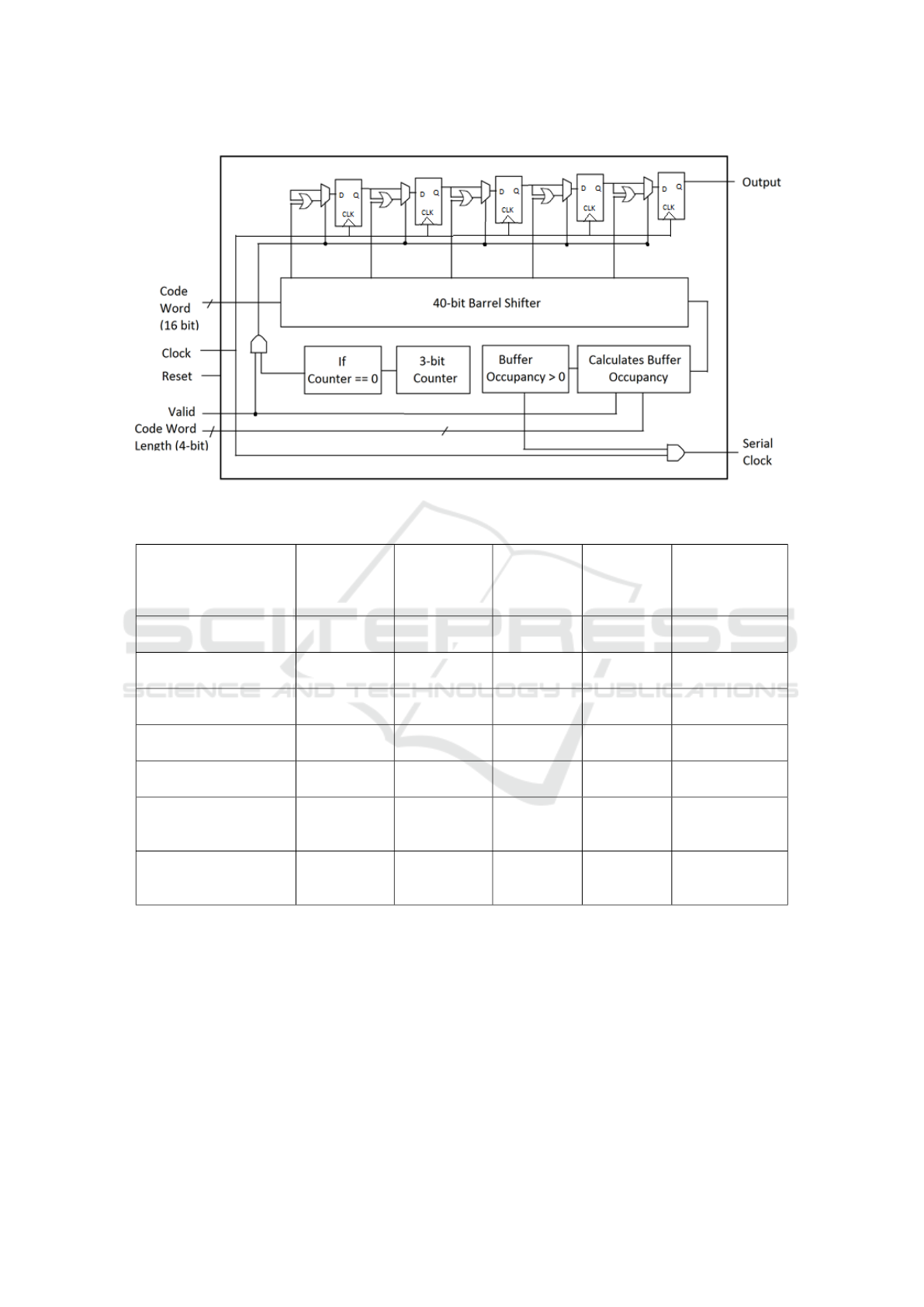
Figure 6: Hardware Architecture of Serialiser.
Table 8: Power Comparison with Previous Works.
Existing Works Process
Technology
Chip Area
(mm
2
)
Gate
Count
Power
Consump-
tion
(mW)
Frame Rate
(fps) (image
size)
ASIC(Khan and
Wahid, 2011a)
0.18 um 0.0256 2k 0.018 2(3*320*240)
ASIC(Khan and
Wahid, 2012)
0.18 um 0.0320 2k 0.042 2(3*256*256)
ASIC(Khan and
Wahid, 2011b)
0.18 um 0.0256 2k 0.042 2(3*256*256)
ASIC (Fante et al.,
2016)
0.13 um 0.018 2.2k 0.035 2(256*256*3)
ASIC (Lin and Weng,
2006)
0.18 um 0.329 31k 14.92 2(512*512*3)
Simulation (This
Work : with New
Serialiser)
0.13 um 0.021 5.5k 0.0169 2(256*256*3)
Simulation (This
Work : with 16 bit Old
Serialiser)
0.13 um 0.019 4.9k 0.0142 2(256*256*3)
vision and multiplication are avoided. The order of
computational complexity of our algorithm is O(n),
which is similar to the design proposed in (Fante et al.,
2016). As compared to their design, we required
some more registers in the DWT block, but overall
we are increasing the compression at a minimal in-
crease in hardware. By limiting the max length of
code to 16 in the Golomb Rice encoder, we simplified
the design of the serialiser. If we consider the com-
pressor along with the serialiser as a unit, then we
obtain higher compression as compared to previous
designs at almost similar hardware complexity and
power consumption. Our implementation requires no
memory buffer and does not require complex compu-
tations.Table 8 compares the power consumption of
our design with the previous works.
5 CONCLUSIONS
In this paper, we presented a hardware efficient image
compressor along with the serialiser for application in
DWT based Low Power Image Compressor for Wireless Capsule Endoscopy
23
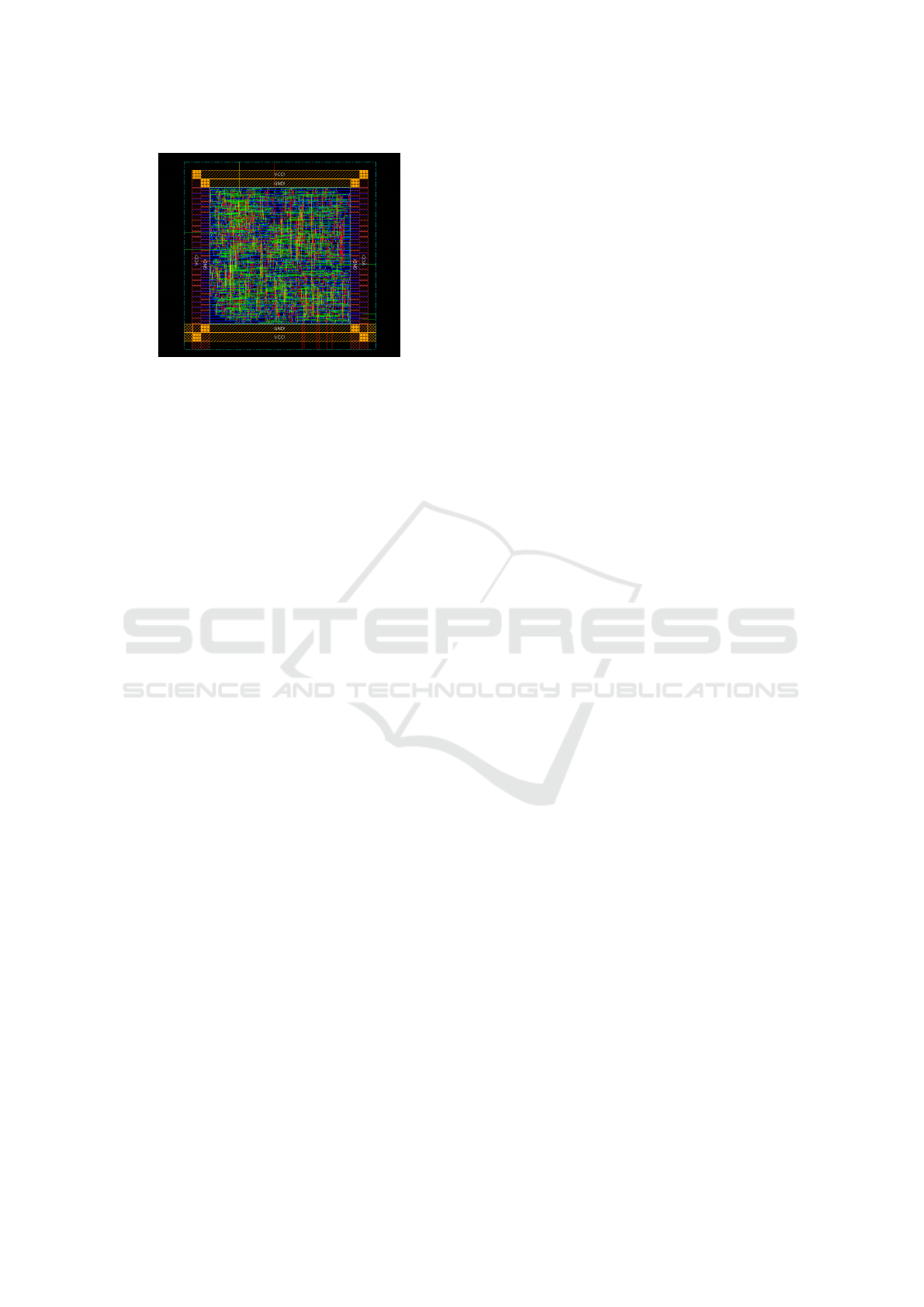
Figure 7: Layout of the Proposed Image Compressor.
wireless capsule endoscopy. It was based on compu-
tationally simple techniques like 1D integer wavelet
transform, DPCM, color transformation and Golomb
Rice encoder. The performance of the algorithm was
evaluated on the basis of PSNR and Compression Ra-
tio. Our image compressor was able to achieve a com-
pression of 91.88 percent at a PSNR 38.17. An alter-
native architecture for the serialiser was also proposed
specific to the implemented algorithm which ran at
only 8 times the frequency of the compressor. The
hardware implementation of the proposed compres-
sor along with two different serialisers using Faraday
HS library standard cells in UMC130nm process con-
sumes 14.2uW and 16.9 uW respectively. The archi-
tecture is designed for a 256*256 image at 2 frames
per second. As compared to the existing DCT based
implementations, we get as good a compression ratio
but with very low power consumption. In comparison
to the DPCM based approaches, our algorithm gives
higher compression with similar power consumption.
Moreover, we were able to optimize the design of the
serialiser so that it works at lower frequency. We be-
lieve that the proposed image compressor along with
the serialiser is a good candidate for WCE applica-
tions as it has a high compression ratio, good recon-
structed image quality, low power consumption, and
small area.
REFERENCES
Bhanu, U. and Chilambuchelvan, D. A. (2012). A de-
tailed suvey on vlsi architectures for lifting based dwt
for efficient hardware implementation. International
Journal of VLSI design and Communication Systems,
pages 207–214.
Bruaene, C. V. D., Looze, D. D., and Hindryckx, P. (2015).
Small bowel capsule endoscopy: Where are we after
15 years of use? World Journal of Gastrointestinal
Endoscopy, pages 13–36.
Cosman, P. C., Gray, R. M., and Olshen, R. A. (1994). Eval-
uating quality of compressed medical images: Snr,
subjective rating, and diagnostic accuracy. In Pro-
ceedings of the IEEE, volume 82, pages 919–932.
Fante, K. A., Bhaumik, B., and Chatterjee, S. (2016). De-
sign and implementation of computationally efficient
image compressor for wireless capsule endoscopy.
Circuits Systems and Signal Processing, 35:1677–
1703.
Gastrolab (2014). http://www.gastrolab.net.
Hale, M. F., Sidhu, R., and McAlindon, M. E. (2014).
Capsule endoscopy: Current practice and future di-
rections. World Journal of Gastroenterology, pages
7752–7759.
Jing, Z., Jin-yun, F., and Cheng-de, H. (2008). The selection
of reversible integer-to-integer wavelet transforms for
dem multi-scale representation and progressive com-
pression. International Archives of Photogramme-
try, Remote Sensing and Spatial Information Science,
pages 1010–1024.
Khan, T. H. and Wahid, K. (2011a). Lossless and low power
image compressor for wireless capsule endoscopy.
VLSI Design.
Khan, T. H. and Wahid, K. (2011b). Low power and low
complexity compressor for video capsule endoscopy.
In IEEE Transactions on Circuits And Systems For
Video Technology, volume 21, page 15341546.
Khan, T. H. and Wahid, K. (2012). Implantable narrow band
image compressor for capsule endoscopy. In IEEE In-
ternational Symposium on Circuits and Systems (IS-
CAS), Seoul, South Korea, page 22032206.
Khan, T. H. and Wahid, K. (2013). Subsample based image
compression for capsule endoscopy. Real-Time Image
Processing, pages 5–19.
Korhonen, J. and Junyong, Y. (2012). Peak signal to noise
ratio revisited: Is simple beautiful? Fourth Interna-
tional Workshop on Quality of Multimedia Experience
(QoMEX), Yarra Valley, VIC, Australia, pages 37–38.
Koulaouzidis, A. and Iakovidis, D. K. (2015). Wireless en-
doscopy in 2020: Will it still be a capsule? World
Journal of Gastroenterology, pages 5119–5130.
Lin, M.-Ch, D. L.-R. and Weng, P, K. (2006). An ultra-
low-power image compressor for capsule endoscope.
Biomedical Engineering Online, pages 1–8.
Memon, N. (1998). Adaptive coding of dct coefficients by
golomb-rice codes. In Proceedings of International
Conference on Image Processing.
Philip, N., Martini, M. G., and Amso, N. (2008). Subjec-
tive and objective quality assessment in wireless tele
ultrasonography imaging. In Proceedings of the In-
ternational Conference of the IEEE Engineering in
Medicine and Biology Society, pages 5346–5349.
Turcza, P. and Duplaga, M. (2011). Low power fpga-based
image processing core for wireless capsule endoscopy.
Sensors and Actuators A: Physical, pages 552–560.
Turcza, P. and Duplaga, M. (2013). Hardware-efficient low-
power image processing system for wireless capsule
endoscopy. IEEE Journal Of Biomedical And Health
Informatics, pages 1046–1056.
BIODEVICES 2017 - 10th International Conference on Biomedical Electronics and Devices
24
