
Fatigue Life Assessment and Experiment Design for EMU Corbel
Wenxue Qian
1
, Qingjie Wang
1
, Zijian Sun
1
, Xiaowei Yin
2
and Liyang Xie
1
1
School of Mechanical Engineering and Automation, Northeastern University, Shenyang 110819, P. R. China
2
Department of Mechanical Engineering, Shenyang Institute of Engineering, Shenyang 110136, P. R. China
qwx99@163.com
Keywords: EMU corbel, Fatigue evaluation, Local stress-strain method, Experiment design.
Abstract: In order to ensure the safe operation of EMU, the fatigue assessment for corbel which a key components of
EMU has been done. To refine the mesh quality for the weak parts of corbel though building a substructure
using workbench software. According to finite element analysis, the local stress-strain method is adopted to
estimate the fatigue life of the corbel. An analysis fatigue condition for corbel to determine the location and
size of loading. Compared the body with single corbel finite element analysis results, determine the beam
fatigue test program.
1 INTRODUCTION
With the development of economy and technology,
the speed of EMU is increasing and the light weight
requirement of car body is improved continuously.
The safety problem of EMU is becoming the key to
the development of motor vehicle technology. The
safety of motor vehicles is not only to meet the
requirements of strength and stability, but also
fatigue life is one of the important indicators. The
corbel is an important component of EMU and the
fatigue performance directly affects the safety of
train operation. The fatigue analysis of corbel's
traction seats were carried out by some
researchers(Han 2012). But right now, the EMU
sleeper fatigue research is less at home and abroad.
At present, the fatigue assessment of large
components mainly include the nominal stress
method, the local stress-strain method, the stress
field intensity method and so on(Zhang 2011). With
the development of the finite element software, the
local stress and strain of the dangerous part of the
large component can be obtained by software
simulation. This has been widely used in the
engineering(Tong 2011). In this paper, the fatigue
life of the corbel is evaluated by using the local
stress strain method combined with the finite
element analysis results. And the fatigue test design
of corbels is carried out combined with the actual
operation of the EMU.
2 FINITE ELEMENT ANALYSIS
2.1 Establishing model and meshing of
corbel
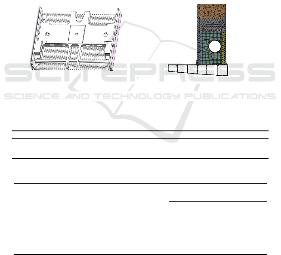
According to the 2D drawing to establish three-
dimensional model of corbel as shown in Figure 1
(a). In the analysis of complex parts, it is necessary
to use rough mesh to determine the dangerous parts,
then the weak parts are refined by using the sub
structure method(Song 2013, Japan Industrial
Standards 2016). The corbel dangerous parts of the
mesh for unit length of 10mm hexahedral elements,
transition region for unit length of 15mm free mesh,
other parts for the unit length of 30mm tetrahedral
elements, the total number of nodes is 1064732,
number of units is 549074.The mesh of key weak
part shows as Figure 1 (b).
2.2 Finite element analysis and
determine working conditions
EMU is great sensitive to environmental changes
because of its high speed. According to the(Wang
2014), it is known that the fatigue condition is
mainly based on the vibration, such as the stability
of the track, body vertical and lateral vibration
8
8
Yin X., Sun Z., Xie L., Wang Q. and Qian W.
Fatigue Life Assessment and Experiment Design for EMU Corbel.
DOI: 10.5220/0006442800080012
In ISME 2016 - Information Science and Management Engineering IV (ISME 2016), pages 8-12
ISBN: 978-989-758-208-0
Copyright
c
2016 by SCITEPRESS – Science and Technology Publications, Lda. All rights reserved
which is caused by the passengers get on or off car,
acceleration and braking of the car to produce
longitudinal vibration. The change of conditions: the
loads of body change between the preparation
conditions (AW0) and overload condition (AW3).
Calculating loads through the AW3 conditions :
Vertical vibration acceleration to take (1+0.15 g);
lateral and longitudinal acceleration take 0.15g. The
main loads of corbel include the vertical load of air
spring seat and the load of the center pin(Liu
2012).The loads condition is shown as Table 1 and
Figure 7.
Using the static structural module of the finite
element software of Workbench to make an
evaluation of the fatigue condition for the corbel.
The material parameters are shown in Table 2
(Sankaran 2011). The constraint boundary
conditions at both ends of the corbel is fixed
constraint. The two load step is set in the program,
and the loading condition is shown in Table 1.1.
Enhanced Lagrange method is used to solve the
model. The equivalent stress and strain calculation
results as shown in Figure 2, the greatly weak point
is the intersection of left the through tube 1 and left
corbel.
At the load step 1, the maximum stress value is
126.13Mpa and the maximum strain value is
1.7781E(-3). At the load step 2, the maximum stress
value is 103.59Mpa, the maximum strain value is
1.46031.4603E(-3), and the other dangerous parts of
the stress cloud is shown in Figure 3.
(a) Three-dimensional model of corbel (b) Meshing of corbel
Figure 1: Model and mesh of corbel
Table 1: Loads condition
Project Number Loads(KN) The direction
Load of the center pin 1 15.5±15.5
With a transverse angle of
45 degrees
Load of air spring seat 2 120±18 Vertical
Table 2: The main corbel Aluminum Alloy material characteristics
Material Position
Elastic
modulus(
GPa)
Poisson
ratio
Density(
Kg/m3)
Elastic limit(MPa)
Fatigue strength
(MPa)
Base
metal
Welding
Base
metal
Welding
A7N01P-T4
(JISH4000)
Corbel
reinforcing
plate
69 0.3 2710
195 176 135
39
A7N01S-T5
(JISH4100)
Corbel left(
right)
245 205 119
Fatigue Life Assessment and Experiment Design for EMU Corbel
9
Fatigue Life Assessment and Experiment Design for EMU Corbel
9
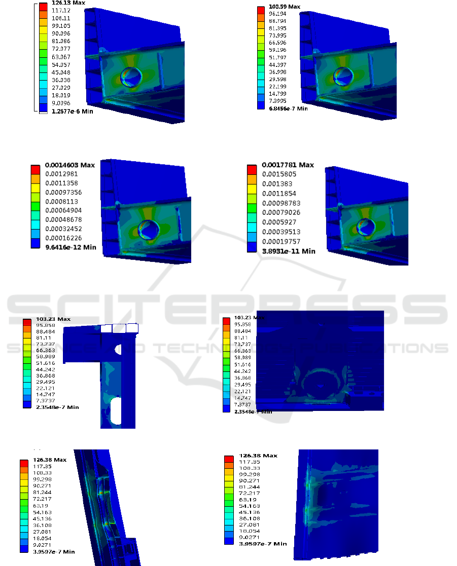
(a) Stress cloud at the load step 1 (b) Strain cloud at the load step 1
(c) Stress cloud at the load step 2 (d) Strain cloud at the load step 2
Figure 2: Stress or strain cloud of the weak point
(a) The intersection of right the through tube 2 and
right corbel.
(b) The intersection of lower cover plate and side member.
(c)The intersection of right the through tube 1 and
corbel inside.
(c)The intersection of left the floor and side member
Figure 3: Stress cloud at different risk positions
ISME 2016 - Information Science and Management Engineering IV
10
ISME 2016 - International Conference on Information System and Management Engineering
10
3 FATIGUE LIFE PREDICTION
OF CORBEL
Corbel as large structures whose nominal stress is
difficult to gain, but the local stress and strain can be
obtained by finite element method. So using local
stress-strain method to evaluate the fatigue life of
the corbel. The strain life curve is usually described
by Manson-Coffin formula, which is based on the
low cycle fatigue strain life relationship (Manson-
Coffin formula) and the high cycle fatigue stress life
relationship (Basquin equation).As type (1)
'
'
0
(2 ) (2 )
f
bc
f
NN
E
σ
εε
Δ= + (1)
In formula (1),
0
ε
Δ represent the total strain
when the average stress is 0;
'
f
σ
represent the
fatigue strength coefficient;
'
f
ε
represent the fatigue
ductility coefficient; b represent the fatigue strength
index; c represent the fatigue ductility index; N
represent the fatigue life(Yin 2010, Qian 2012).
In equation (1) for the Manson-coffin formula
under fluctuating load, the non fluctuating load need
to be modified to the average stress, and the average
stress is modified by the total strain of Morrow,
follow the formula (2):
'
0
'
f
fm
S
σ
ε
ε
σ
Δ= Δ
−
(2)
In formula(2):
ε
Δ
represent total strain whose
average stress is corrected;
m
S represent the average
stress value.
Through finite element analysis to ensure the
critical points of corbel is in through pipe. The
maximum stress is 126.13Mpa,and the minimum
stress is 103.56mpa,whose material is A7N01S-
T5. Material’s tensile strength is 245Mpa 、
reduction of area is
11.5%
ψ
=
. Calculating that:
114.86
m
S
=
,
'
0.16252
f
ε
= ,
'
0.16087
f
ε
= ,
'
618.8
f
σ
= , applying the
parameter to (1)、(2):
0.12 0.6
3
618.8
1.228 (2 ) 0.1681(2 )
69 10
NN
ε
−−
−
⎡
⎤
Δ= × +
⎢
⎥
×
⎣
⎦
The finite element calculation results show that
the dangerous point strain is
0
3.178E( 4)
ε
Δ= −
.
The fatigue life of corbel is
7
10N > .
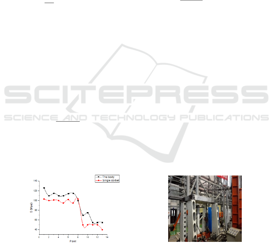
4 CORBEL FATIGUE TEST
test points. Using the finite element software to
analyze the body of fatigue working condition and
the same conditions corbel analyzed separately
scheduled monitoring results as shown in Figure 4,
the same detection should be a smaller force
deviation, corbel constraint and load method is
reliable. The constraint imposed on the side beam
and corbel test loading clamp mode is shown in
Figure 6, load size as shown in Table 1.1 shows,
load location and direction as shown in Figure 7.
Load test for hydraulic drive, the test frequency is
3Hz, corbel fatigue test site as shown in Figure 5.
F
igure 4: Results of key point of vehicle and corbel alone
Figure 5: Fatigue experiment
Fatigue Life Assessment and Experiment Design for EMU Corbel
11
Fatigue Life Assessment and Experiment Design for EMU Corbel
11
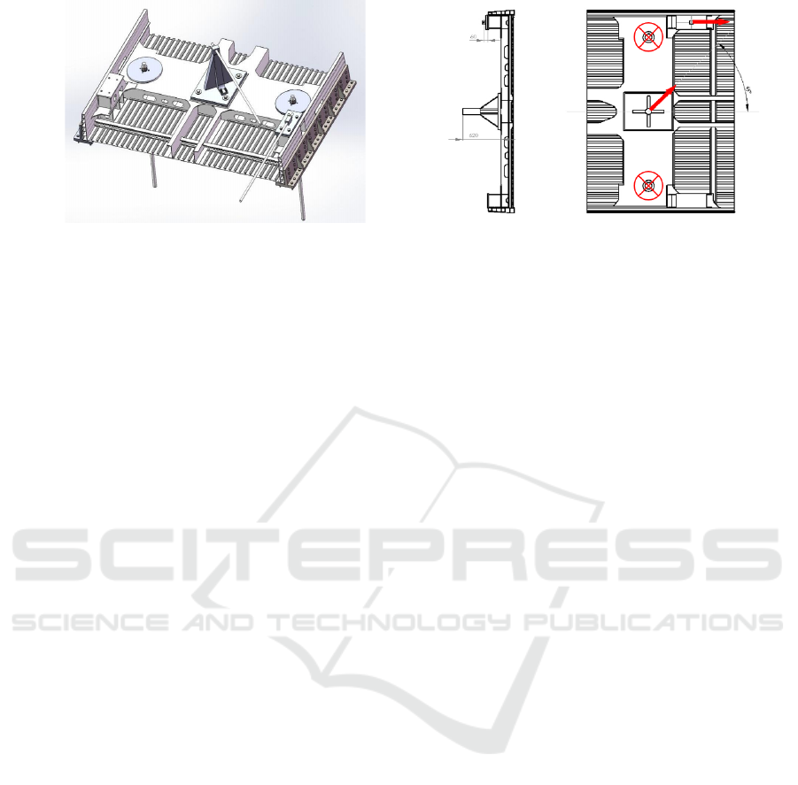
Figure 6: Fixture of corbel test Figure 7: Loading position and direction
5 CONCLUSIONS
1) The evaluation of fatigue life by local stress strain
method is conservative and accurate, and it is safe to
be applied in engineering application;
2) Using the finite element software workbench to
analyze corbel fatigue working condition, Applying
the results of analysis to Manson coffin equation to
obtain the dangerous position of the corbel fatigue
life, which is
7
10N > . Satisfying fatigue life
requirements;
3) Corbel fatigue test can be carried out
independently. Do not need to analyze the whole
body.
ACKNOWLEDGMENTS
This work was partially supported by the National
Natural Science Foundation of China (Grant No.
51305275, 51335003, 51275221), the Program for
Liaoning Excellent Talents in University (Grant No.
LR2015044), the Fundamental Research Funds for
the Central Universities (Grant No. N140301001),
and the Natural Science Foundation of Liaoning
Province of China (Grant No. 2015020138).
REFERENCES
Han T, Liu Z, Li Q, et al, 2012. Evaluation of Fatigue Life
and Reinforcing Scheme on 6K Electric Locomotive
Traction Seats[J]. Procedia Engineering, 45(2): 930-
935.
Japan Industrial Standards: General specification for
design of railway vehicle body, 2006 (JISE7106-2006)
Liu X, Zhang L, Wang L, et al, 2012. Fatigue behavior
and life prediction of A7N01 aluminium alloy welded
joint. Transactions of Nonferrous Metals Society of
China, 22(12): 2930-2936.
Qian Wenxue, Yin Xiaowei, Xie Liyang, 2012. System
Reliability Allocation Based on Bayesian Network.
Applied mathematics & information sciences, 6(3):
681-687.
Sankaran Mahadevan, Ruoxue Zhang, 2001, Natasha
Smith. Bayesian networks for system reliability
reassessment. Structural Safety, 23(3): 231-251.
Song Shaoyun, 2013. Mechanical design and
manufacturing of parts in static simulation of assembly
body. Mechanical design and manufacture, (9): 224-
226.
Tong Dihua, Chen Zhiwei, 2011. Local should reform
prediction hole part of the fatigue life. Aviation
Materials Journal of aircraft structural belt, 31 (5): 86-
90.
Wang Boming, 2014. General and bogie of high speed
train car group. Chengdu: Southwest Jiao Tong
University Press: 143-144.
Yin Xiaowei, 2010. Common Cause Failure Model of
System Reliability Based on Bayesian Networks.
International Journal of Performability Engineering,
6(3): 160-170.
Zhang Xiaoli, Chen Xuefeng, Li Bing, et al, 2011. A
survey of the life prediction of machinery major
equipment. Journal of Mechanical Engineering,
47(11): 100-116.
ISME 2016 - Information Science and Management Engineering IV
12
ISME 2016 - International Conference on Information System and Management Engineering
12
