
Is it Possible to Detect the Stealth Flying Objects by the
Millimetre Wave Radiometer?
Jinghui Qiu, Shengchang Lan, Hao Liu, Xinyu Yin and Alexander Denisov
Department of Microwave Engineering, Harbin Institute of Technology, P.R.China
Xiao Qing and Zhao Man
Southwest Institute of Electronic Equipment, Chengdu, P.R.China
Francesco Soldovieri
Istituto per il Rilevamento Elettromagnetico dell'Ambiente Consiglio Nazionale delle Ricerche, Napoli, Italy
Keywords: Microwave radiometer, Passive millimetre wave imaging system, Remote sensing control, Antiradar coating
Abstract: This work evaluates the possibility of using the passive millimeter waves (PMMW) radiometric
discriminator for the remote control and the detection of stealth aircrafts.
1 INTRODUCTION
Microwave radiometry is concerned with
measurements of natural electromagnetic radiation of
an object of physical temperature above 0° K.
A large literature describes the main working
principles of microwave radiometry (Reinwater,
1978; Moffa et al, 2001; Goldsmith et al,1993;
Appleby and Lettington, 1991; Piechl, 2004;
Poradish and Habbe, 1982; Esepkina et al, 1973;
Skou, 1989; Shuchardt et al, 1981). With respect to
special application fields, it is interesting also to read
old publications and patents regarding military
designs and applications based on the deployment of
millimeter wave bands during the Cold War
(Shuchardt,1978; Moore et al., 1976; Parnell, 1988;
Seashore, Miley and Kearns, 1979; Corrado, 1988;
www.giws.de). After, due to the large potential
market, there has been a large diffusion of modern
microwave firms for the equipment of the airport
security systems and the detection of the concealed
objects.
Based on the growing problem of the terrorism,
especially after 11 September 2001, a large amount
of money has been devoted to special programs for
the design of special passive millimeter wave
imaging systems (PMMW) (Proc..of SPIE a lot of,
Huguenin,2006; Appleby,2007; Internet,Dill et al.
2009).
The focus of the present work is on the possibility
offered by PMMW radiometric systems in order to
detect remote aircraft with antiradar surfaces
coverage (Figure 1).
A relevant statement about the use of an anti-
radar surfaces adapted to the stealth ship is provided
just below. (wikipedia.org/wiki/Stealth ship). “In
designing a ship with reduced radar signature, the
main concerns are radar beams originating near or
slightly above the horizon (as seen from the ship)
coming from distant patrol aircraft, other ships or
sea-skimming anti-ship missiles with active radar
seekers. Therefore, the shape of the ship avoids
vertical surfaces, which would perfectly reflect any
such beams directly back to the emitter. Retro-
reflective right angles are eliminated to avoid causing
the cat’s eye effect. A stealthy ship shape can be
achieved by constructing the hull and superstructure
with a series of slightly protruding and detruding
surfaces”.
Anyway, it is sufficient to change the word from
“ship” to “aircraft”.
The stealth coating it is very suitable to avoid the
specular reflection for active systems, but at the
same time is practically useless for radiometric
systems, because nature produces radiations, which
re-reflect from this surfaces to antenna of radiometer
from the every directions (Figure 2 and 3)
61
Qiu J., Lan S., Liu H., Yin X., Denisov A., Qing X., Man Z. and Soldovieri F.
Is it Possible to Detect the Stealth Flying Objects by the.
DOI: 10.5220/0006227200610068
In Proceedings of the Fifth International Conference on Telecommunications and Remote Sensing (ICTRS 2016), pages 61-68
ISBN: 978-989-758-200-4
Copyright
c
2016 by SCITEPRESS – Science and Technology Publications, Lda. All rights reserved
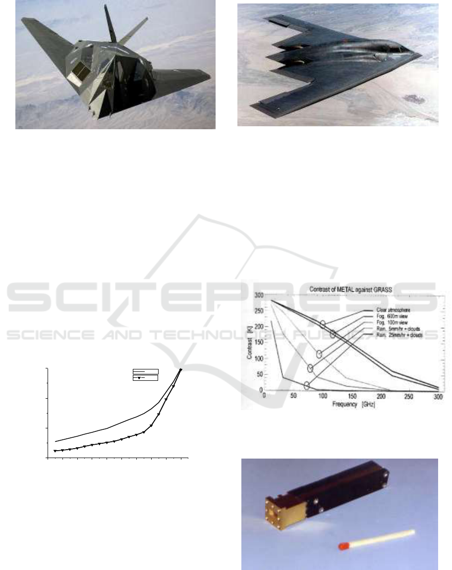
Figure 1: Photos of various modern famous special aircrafts with antiradar surfaces.
Objects reflect and emit radiation in the
millimeter wave range as they do it in the infrared
and visible ranges. The degree to which the object
reflects or emits is characterized by emissivity ε. A
perfect radiator (absorber) has ε = 1 and is known as
a blackbody (Esepkina, 1973). A perfect reflector
(non-absorber) has ε = 0. The earth and the sky can
be approximated as blackbody, whereas the metal
object is a reflector. Intermediate values of the
emissivity ε depends on several parameters as,
dielectric properties of the objects, angle of
observation (for example, for the water surface), the
polarization parameters, the surface roughness or
coatings, the wavelength and other factors.
8mm
0 10 20 30 40 50 60 70 80 90
0
100
200
300
Brightness temperature (K)
Incidence angle from zenith()
3mm
Figure 2: Brightness temperature of sky at the various
angles of relatively zenith.
The measurement of such a radiation is more
correct and understandable in terms of radio
brightness (simply brightness) temperature, which is
expressed in temperature T.
According to the usual definition (Esepkina,
1973), a radiometer (Figure 4) is a receiving device
designed for the measurements of the level of noise
radiation in an assigned band of the frequencies Δf.
The main functionality of the receiver in a
radiometer is to provide a measure of the input noise
power, expressed as an antenna temperature, in
equivalent black body temperature units. The
sensitivity of the radiometer ΔT
sens
,
is defined as the
minimum detectable signal and is determined by
amplitude of the fluctuations presented at the output
indicator in the absence of the signal.
Figure 3: Possible radio-brightness radiometric contrast
between metal and grass at the zenith angle for the case of
the observing an obects on the earth surface
Figure 4: Picture of the 8 mm radiometer (Gorishnyak et al,
2004).
Fifth International Conference on Telecommunications and Remote Sensing
62
Usually, the temperature sensitivity of radiometer
is evaluated for post-detection time 1 sec. More
details about various situations concerning ΔT
sens
(calculated and measured) can be found in (Esepkina,
1973; Skou 1989).
The bottom of the aircrafts will reflect the
radiation of the hot Earth and accordingly it will be
seen by the radiometer as an hot object with respect
to the background of the cold sky (space).
Even in case of the coating of all surfaces by
special absorption (small probability) material
(“painting”), such a “blackbody” will have surface
brightness temperature as from outside of the aircraft.
Remember standard information at the board during
the air flight: “Temperature of air overboard makes
minus 56 degrees.
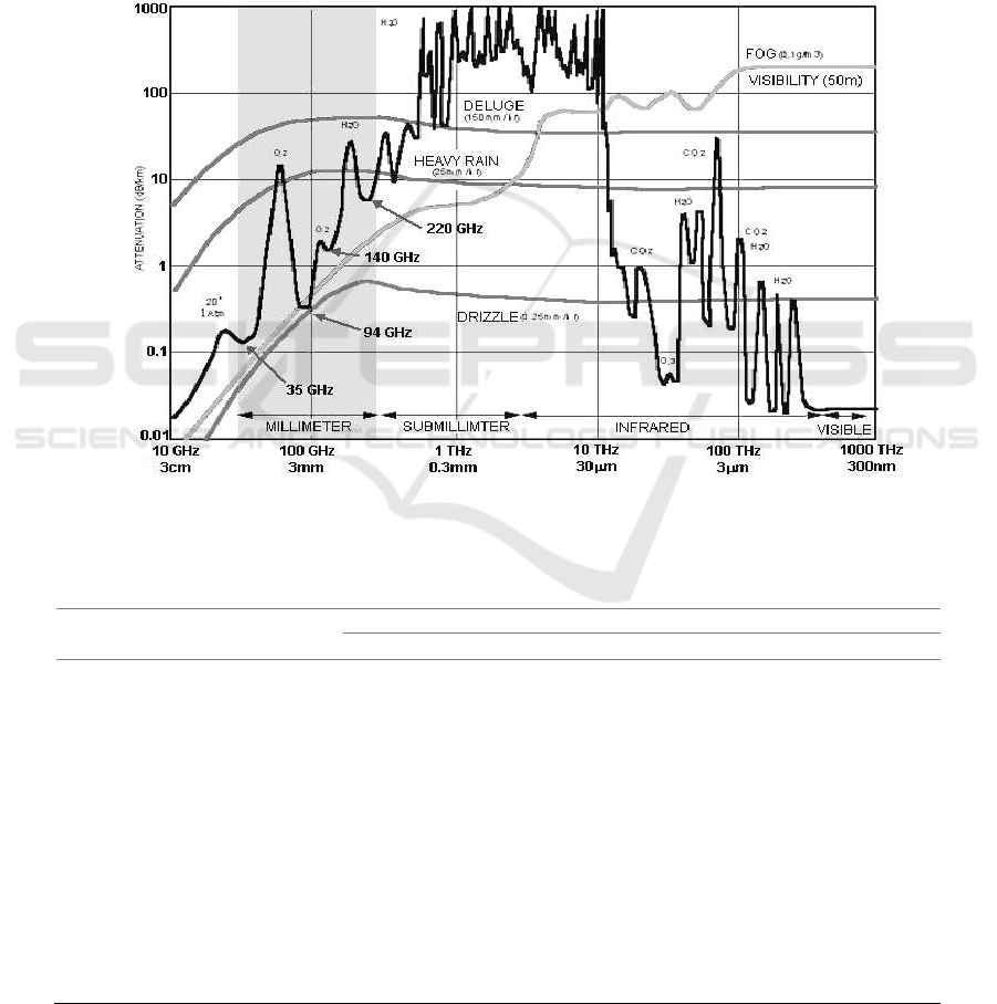
In this paper, we evaluate the possibility of using
PMMW radiometric system for the remote control
and the finding of stealth aircrafts. The choice of the
real working frequency depends on the real size of
antenna and the microwave losses in atmosphere on
path radiometer – aircraft (Figure.5 and Table 1).
Figure 5: Absorption of the electromagnetic waves in the atmosphere
Table 1: Absorption in atmosphere for Three Window Frequencies (Seashore et al, 1979)
CHARACTERISTIC
FREQUENCY
35GHz
94GHz
140GHz
Wavelength
8.6mm
3.2mm
2.2mm
Clear Air Attenuation
0.12dB/km
0.4 dB/km
1.6 dB/km
Rain Attenuation
0.25mm/hr
0.07 dB/km
0.17 dB/km
0.2 dB/km
1.0 mm/hr
0.25
0.6
0.7
4.0 mm/hr
1.0
3.0
3.2
16.0 mm/hr
4.0
8.0
9.0
Fog Attenuation
Light 0.01g/m
3
0.006 dB/km
0.035 dB/km
0.07 dB/km
Thick 0.1 g/m
3
0.06
0.35
0.7
Dense 1.0 g/m
3
0.6
3.5
7.0
Apparent Sky Temperature
Clear
23°K
50°K
81°K
Moderate Overcast
65
120
200
Rain
110
220
250
Is it Possible to Detect the Stealth Flying Objects by the
Millimetre Wave Radiometer?
63
2 TECHNICAL DETAILS
2.1 Passive Millimeter Wave Imaging
A very increasing interest towards the design and
production various PMMW imaging system is due
to the real possibility to have fourth type of the
remote control system in addition to the existing
optical, radar and infrared (IR) systems. Attractive
feature of PMMW imaging systems is the capability
to operate under adverse weather conditions and to
be sensitive to non-metallic targets. In addition,
since PMMW sensor is passive, it can be operated in
all locations including friendly and hostile ports
where RF emissions may be disruptive to local
systems. (Moffa et al, 2001).
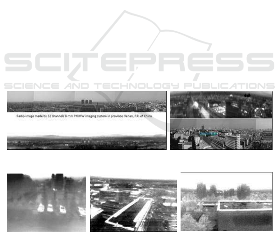
Figure 6 presents images produced by the 32
sensors 8 mm PMMW system with antenna diameter
90 cm (Gorishnyak et al, 2004; Denisov et al, 2009).
For this system, sensor sensitivity is 0,01 K for post
detecting time 1 sec and the sensor works without
any modulation-calibration at the entrance. This
system according to the theory works with full
power radiometers. In figure 6, it is worth noting
that the black spots on the image of city, at the top of
building, represent the mobile phone transmission
stations, producing harmonics in 8 mm band. Radio-
images in 90 GHz (3mm wavelength) frequency
band presented on Figure 7.
PMMW system are now gaining of deep cooling
based on superconductors for the space tasks
(Proc.of SPIE,2014) and the improvement of the
passive images, with the help of advanced data
processing, for the super resolution (Luxin et al.
2006). In the near future, it is expected the modern
application of the processed radio-images in the
various spectral bands with the help of a correlation
analysis.
2.2 Technical Peculiarities of the
Radiometric Discriminator
Good performance of radio-image systems is based
on the necessity to have identical sensors; this is not
challenging in case of a direct amplifier based on the
Monolithic Microwave Integrated Circuits (MMIC)
with enough high dynamic range. Instead, various
issues arises in the data processing, when we have to
turn from the measurements with a large number of
sensors in an image in a digital form or in optical up-
converting “looks”. Issuers regard also special
cooling (Moffa, 2001) and temperature stabilization,
which really increases the cost of PMMW system.
For example, prime cost of 8 mm sensor in Figure 4
has value around 700 $, and for modern European
direct amplifiers on 3 and 2,2 mm the cost is 5-20
times more expensive.
Figure 6: Radio-images in 8 mm wave band in comparing with the optical images of the same scenes.
Figure 7: Radio-images in 3 mm wave band
Fifth International Conference on Telecommunications and Remote Sensing
64
sensors, because the relevant angle of view is
enough small in this case.
Here, we focus on the differential modulation
radiometer, which is also named by discriminator.
Reciever
Voltmeter
Computer
Power
Source
reflector
Modulator
Demodulator
Intergrator
Modulator
Figure 8: Block-scheme of the simplest 8 mm microwave
discriminator.
The discriminator (see Figure 8) exploits two
feeders combined with the one antennas surface. The
special antenna system forms two space beams
directed on the two neighboring directions of the
space in the horizontal plane (the same device can be
done for the vertical plane). The angle between the
two beams depend on the technical specification.
The incoming signals from these two directions are
at the input of the switch and later to the radiometer
(Figure 8). Usually, it is convenient to deploy a
circulator in replacement of the switch where
radiometer is connected to the third gate of the
circulator. In this configuration, at the input of the
radiometer there are two microwave signals at the
modulation frequency (for example, 10 kHz). After
amplification (around 56 dB), the signal are detected
and are going as the meander with modulation
frequency. Afterward, the resulting signal can be
demodulated by the synchronous detector with time
constant around τ = 0.01sec. Finally, at the output of
the integrator (discriminator), there is a signal
proportional to the difference of the power in the
measured beams. This signal difference arises only
in case of observation of different observed scenes.
Therefore, as the result of the scanning, there is a
picture that resembles the two neighboring angles of
the space and accounts for the contour of the
observed object.
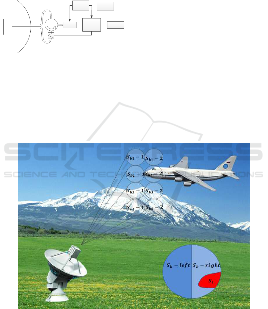
2.3 The Job of the Discriminator
For a simple explanation of the working principle of
the discriminator, we can refer to Figure 9.
Figure 9: Pictorial description of the working principle of a discriminator.
There the four channels PMMW discriminator
system produces the scanning of scene. The first
spot of the antenna beam S
b-left
, does not intercept
any part of the observing object whereas the object
Is it Possible to Detect the Stealth Flying Objects by the
Millimetre Wave Radiometer?
65

There the four channels PMMW discriminator
system produces the scanning of scene. The first
spot of the antenna beam S
b-left
, does not intercept
any part of the observing object whereas the object
is imaged in the second right spot S
b-right
,.
For an evaluation of these two following
observing spots, the brightness temperatures T of the
object is used. The brightness temperature can be
evaluated according to the expression concerning the
microwave power P =
kTΔf, where k –Boltzmann’s
constant, T–brightness temperature, Δf- the band of
the receiving frequencies, which income to the
radiometer from the two antenna’s spots. Of course,
this task requires a critical technology
(Huguenin,2006, Dill et al,2009). In Eq.1 there is
S
back
= πA
2
, where A is the area of the aperture
antenna beam spot at the distance L till the aircraft.
Other main parameters are: the brightness
temperature of background (cold sky) is T
back
,
(concerned with S
b2
-1, S
b1
-1, S
b1
-2
on fig.9), this
value is dependent on the atmosphere conditions and
in particular on the absorption in atmosphere, which
increases the brightness temperature of sky
compared to the case of clear air. The diameter of
the antenna’s beam spot is A= 1,22 L sin λ/D. S
t
–
area of the aircraft surface inside of the beam spot
Sb
2
-2
with the brightness temperature of the aircraft
depending on the reflection from the earth or water
T
t
.
In the inset of Figure.9, we schematically present
two parts of the antenna beam spots S
b-left
and S
b-
right
. Both S
b-left
and S
b-right
are two half of the full
surface of S
b
. Discriminator compares the received
signals from these two beam spots; the difference
between the received microwave power in terms of
the brightness temperatures of these two spots can
be evaluated in the simplest approximation as :
(1)
So, if the receiver of discriminator has a
sensitivity better that the result of eq. (1), it is
possible to detect the distinction inside of this
direction and the objects can be found by PMMW
discriminator system.
Every antenna has the efficiency η (for example,
in percents). On the track object – radiometer,
attenuation in atmosphere and losses from the
antenna to the input of the radiometer can be
accounted by the parameter α (expressed in dB or
times). Every measuring system must have a reserve
in the probability of detection of κ (signal/noise).
If we consider
Contrast
= T
back
-
T
sky
, it is
possible to recognize an aircraft, under a simple
approximation in case of :
Contrast
≥κ α Δ T
sens
S
b-right
/ S
t
η σ
(2)
Obviously, it is desirable to have a large contrast
Contrast,
which depends on the environmental
conditions, the brightness temperature of sky (Figure
2), the polarization effects, the working frequency,
the material and geometry of the reflecting surfaces
of the observed flying objects and position of
observing object of relatively horizon, zenith and
sun. Right part of Eq.2 depends on the sensitivity
ΔT
sens
, microwave losses in atmosphere α and (S
b-
right
/S
t
). If we consider the sensitivity of radiometer
for post-detection time 1 sec, real value is 0,01 K for
8 mm and in 3 mm practically too. There are no big
problems to do the radiometric system at the base of
modern MMIC with good thermal stabilization,
which is the key factor to filter out possible
amplification drift between the multitude of sensors.
In principle by using MMIC with more small noise
factor or special cooling, it is possible to reach best
sensitivity, as for example, for the space investigation
(Proc. of 22th ISSTT ), but this is not of interest in the
application considered in this paper. By turning to the
value S
t
/S
b-right
which defines the percent of the
filling an aperture antenna ‘s beam spot by the
surface of aircraft, which according to aerodynamics
must have enough big figure in comparing with an
armor objects, for example, on the earth
(www.giws.de). Table 2 presents the diameter of the
antenna’s beam spot at the various distances from an
antenna as the function of its diameter. According to
the picture in fig.5 and Table 2, it is possible in good
approximation to evaluate the real microwave losses
on path between radiometric discriminator and the
aircraft to be observed.
b-right
t
back
b-right
t
t
t
b-right
back
back
S
S
T
S
S
T
t
S
t
S
T
T
t
)
(
Fifth International Conference on Telecommunications and Remote Sensing
66
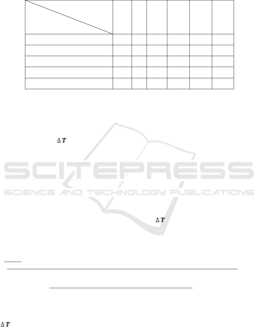
Table 2: Diameter of antenna bean spot versus the distance from the antenna for the 8 mm wavelenght
Distance (km)
Diameter of antenna (m)
2
4
5
10
15
20
0.9
22
43
57
108
162
216
1.0
19
39
49
97
146
194
1.2
16
32
40
81
121
162
1.5
13
26
32
65
97
130
2.0
10
19
24
49
73
97
2.4 Simplest Calculation of the Possible
Distance
Let's try to use Eq.2 in two real cases, concerning
possible contrast levels
Contrast
as 250 K and
100 K (fig.9).
Range of radio brightness contrast ΔT
Contrast
for
the situation presented in Figures 2,3,9 and Table 1
can be from 23 till 270 K.
Real parameters of the discriminator:
- Radiometer sensitivity is 0.01 K for post
detection time 1 sec, at the real time for the analysis
(doing pixel) as τ = 10 msec, ΔT
sens
for this scanning
rate will be 0.1 K
.
- Wavelength λ = 8 mm
- The diameter antenna discriminator D, for
example - 200 cm (not so big problem to do it for 8
mm, if the accuracy of the surface must be worse
that λ/10). Diameter of an antenna spot at the
distance L is
/D)( 1.22L = A
and accordingly S
b
is π A
2
/=
4//D)]( 1.22L [
2
. S
b-left
=S
b-right
= 0,5πA
2
/4,
according to inset on fig.4.
- The antenna efficiency, for example, η = 0,8.
- The factor of the object position σ (σ = 0,8)
- The size of the appearing object inside of the
antenna beam spot S
t
is 5 x 10 m
2,
(middle size ship).
- The probability of detection of κ (S/N) = 3-10
times. (Accept κ = 5)
- The attenuation or microwave losses between
discriminator and observed ship α (3….10 dB).
(Accept α =6 times).
In this case it will be Eq.3:
Δ T
sens <
S
t
η σ
Contrast
/
κ α 0,5 π (L 1,22 λ/D)
2
/4
(3)
Arithmetical calculations will provide
0,1 K <
50 x 10
4
cm
2
x 0,8 x 0,8 x ( 100…250 K) x (200 cm)
2
x 4 / 5 x 6 x 0,5 x 3,14 x L
2
x (1,22)
2
x 0,64 cm
2
(3.1)
L
2
< (100…250) x 50 x 0,64 x 16 x 10
8
/ 15 x 0,64 x 4,68 x 0,1
(3.2)
..
According to (3-1) the value L for the best case
(contrast equal to 250 K) will be 16,87 km. For
Contrast
of 100 K, the distance decrease at about
10,67 km. These evaluations have been made under
the assumptions of S
t
= 50 m
2
, but according to
Internet the real wing surface of the left aircraft on
the Figure 1 is 73 m
2
, and the right one has surface
478 m
2
!
It is worth noting that for the evaluations in the
case of a UAV, if we use the reflecting surface of
about 1 m
2
(really it is more smaller for the
observing UAV), the value L will be around 2,4 Km
for the same discriminator antenna size.
Is it Possible to Detect the Stealth Flying Objects by the
Millimetre Wave Radiometer?
67

3 CONCLUSIONS
For the cases where the PMMW kvazi image is not
so principle it can be used simple microwave
discriminator which is variety of the differential
modulation radiometer for the detection of an
objects. In this case, the receipted results can repeat
the contour of the observing objects.
REFERENCES
Reinwater J. 1978, Radiometers: Electronic Eyes that “See
Noise”, Microwaves, September, p.58-62.
Moffa P.,Yujiri L.,Agravante H, deAmici D., Fornaca S.,
Jackson C., JaegerT,.Jordan K.,Quonh.,Rasmussen K.,
Samec T., Shoucri M., 2001, A large aperture passive
millimeter wave pushbroom camera, Proc. of SPIE,
vol.4373, p. 1-6
Goldsmith P., Hsieh C,.Huguenin G, Kapitzky J., Moore E.
1993, Focal plane imaging systems for millimeter
wavelength”, IEEE Transaction on Microwave Theory
and Techniques, Vol. 41, 10
Appleby R., Lettington A. 1991, Passive millimeter wave
imaging, Electronics & Communication Engineering
Journal, February, p.13- 16
Piechl M., H.Suss H., Greiner S., Jirousek M. 2004,
Imaging Technologies and Applications in Microwave
Radiometry, EuRAD - 2004, Amsterdam, p.269-272
Paradish J., Habbe J., 1982 Millimeter wave radiometric
imaging, Proc. of SPIE, vol.337, p.170-181
Proc.of SPIE , Passive Millimeter Wave Imaging
Technology, Numbers- 3064, 3378,3703, 4032, 4373,
5077, 5619, 5789, 6211,6548,7837, 7854, 8544, 8716,
9253, 9252.
Esepkina N., Korol'kov D., Pariiskiy Y., 1973
[Radioteleskopy i radiometry (Radiotelescopes and
Radiometeres), Nauka Press, Moscow
Skou N., 1989, Microwave Radiometer Systems, Design
and Analysis, Artech House.
Schuchardt J.,, Newton J., Morton T., Galliano J., 1981,
The coming of mm-wave Forward Looking Imaging
Radiometers, Microwave Journal, June, p.45-62
Schuchardt J., Stratigos J., 1978, Detected noise levels
guide radiometer design, Microwaves, September,
p.64-7
Moore R., Hawthorn C., Hoover M., Gravlin A., 1976,
Position Updating with Microwave radiometric
sensors, NAECO-76, Record, USA, p.13-19
Parnell W., 1988, Multiband Design boosts resolution of
imaging radar, Microwaves & RF, September, p.85-94.
Seashore C., Miley J., Kearns B., 1979, MM-wave radar
and radiometer sensors for guidance systems.
Microwave Journal, August, p. 47-58.
T. Corrado T., 1988, Smart munitions-are they affordable.
MSN, December, p.32-36, Site: www.giws.de
Huguenin G. 2006, The detection of hazards and screening
fir concealed weapons with passive millimeter wave
imaging concealed threat detectors, Press release, Site:
www.millivision.com
Appleby R., Wallace H.B., 2007, Standoff detection of
weapons and contraband in the 100 GHz to 1 THz
region, IEEE Trans. on Ant. and Propogation, vol.55,
no.11, p.2944-2956 Sites: www.brijot.com,
www.millivision.com, www.xytrans.com, www.
thruvision.com
Dill S., Piechl M., Jirousek M.,Suss H., 2009, Further
analysis and evaluation of the results of Common
Shield –DAT № 7 experiment- Defence Againstbn
Terrorism, Proc.of SPIE, vol.7485, 74850B-2. Site:
en.wikipedia.org/wiki/Stealth_ship
Gorishnyak V., Denisov A., Kuzmin S., Radzikhovsky V.,
Shevchuk B., 2004 , 8 mm Passive Imaging System
with 32 channels , EurRAD , Amsterdam, Netherland,
2-14 October.
Denisov A., Gorishnyak V., Kuzmin S., Miklashevich V.,
Obolonsky V., Radzikhovsky V.,Shevchuk B.,
Yshenko B., Uliz’ko V., Son J.Y., , 2009, Some
experiments concerning resolution of 32 sensors
passive 8mm wave imaging system, Proceedings of
the International Symposium on Space Terahertz
Technology, Charlottesville, USA.
Proc. of 22th International Symposium on Space Terahertz
Technology, 2011, Tucson, USA, and 2014, Proc. of
SPIE, vol. 9153
Luxin Y., Tianxu Z.,Sheng Z., Jian H., Jianmao Z., 2006,
Study on multichannel passive millimeter-wave
radiometric imaging and superresolution, Int.
J.Infrared Milli. Waves, vol.27, p. 1403-1414
Salmon N., Masan I., Wilkinson P., Taylor C., Scinluna P.,
2010, First imagery generated by near-field real-time
aperture synthesis passive millimeter wave imagers at
94 GHz and 183 GHz, Proc. of SPIE, vol.7837,
78370I
Salmon N., Wilkinson P., Taylor C., 2012 Interferometric
aperture synthesis for next generation passive
millimeter wave imagers, Proc. of SPIE, vol.8544,
854405
Fifth International Conference on Telecommunications and Remote Sensing
68
