
Modeling Semantics sans Mathematical Formalism
Reuven Gallant
Deparment of Computer Science and Engineering, JCT Lev Academic Center, 21 HaVaad HaLeumi St., Jerusalem, Israel
Keywords: Executable Modeling, Formal Methods, Graphical Modeling Languages, Production Quality Code, Syntax,
Semantics, Semantic Mapping, Simulation, UML.
Abstract: Much ink has been spilled regarding the trials and tribulations of adapting formal methods to the needs of
software engineering practitioners With the exception of computer scientists with a passion for algorithm
design and optimization, a plethora of Greek letters and symbols can be an anathema to those whose first
love is writing code. The advent of graphical modeling languages such as UML, and supporting tools that
generate production quality code, executable modeling behavioral simulations for bridging the gap between
formalism and coding. This paper proposes, with illustrative examples, an exploratory learning modality, by
which the practicing engineer can investigate and empirically learn the semantic mapping of UML syntax to
the semantic domains of system instantiation and reactive behavior.
1 INTRODUCTION
The efficacy of formal methods has always been a
hard sell to in-the-trenches software engineering
practitioners whose core responsibility (and first
love) has been to produce working code. Seminal
papers on the subject prefixed with the phrase “Ten
Commandments…” (Bowen and Hinchey, 1995)
(Bowen and Hinchey, 2005) reinforce the perception
the suspicion that such methods are to be imposed in
the same way that a child dutifully attends Sunday
school, glancing furtively at the clock to see how
much longer she must endure the ordeal before
running out to play ball with her friends.
Champions of formal methods are not oblivious
to this reluctance, and thus apologize for and/or
purge Greek symbols and the like from formal
notations (Harel and Rumpe, 2004), (Bowen and
Hinchey, 2005). Greek hieroglyphics aside, the
selected modeling notation and its semantics must be
appropriate for the intended audience, e. g, users,
language developers, methodologists, and tool
vendors (Harel and Rumpe, 2004). Of these
audiences, (Evermann, 2008) follows the traditional
dichotomy between conceptualization and
implementation. UML was “originally developed to
describe software artifacts… More recently, UML
has been used for conceptual modeling of
application domains.”
This sharp dichotomy between software and
conceptual approaches deprives software
practitioners of the excitement generated by Ada
83’s promise of robust, software mimicking real-
world domain objects (Booch, 1983). All one had to
do, (as was done in numerous courses based on
Booch’s seminal work, was to mark the various parts
of speech of the words of a terse problem statement,
and robust easily understood software would almost
jump out of the paper on which this marked up
problem statement was inscribed. Of course, the
application of object concepts to systems far more
complex than those presented in textbooks has been
a sobering experience. Intuitive solutions, yielded to
counter-intuitively constructed systems. Dependency
inversion, canonized in (Gamma et. al, 1995) was
marshalled to mitigate the repercussions of change.
Intuitive comprehension was sacrificed to software
maintainability.
The author of this paper argues that software
concretization, and the joy of conceptualization,
need not remain in the exclusive purview of
requirements engineers, and other non-software
stakeholders. For these stakeholders, the concrete
semantic domain is comprised of application domain
concepts, taxonomically formalized via stereotypes
and tagged values. The software practitioner need
not be deprived of a similar experience. However,
the software practitioners semantic domain is
comprised of generic software concepts such as call
44
Gallant, R.
Modeling Semantics sans Mathematical Formalism.
DOI: 10.5220/0006098900440054
In Proceedings of the 7th International Workshop on Software Knowledge (SKY 2016), pages 44-54
ISBN: 978-989-758-202-8
Copyright
c
2016 by SCITEPRESS – Science and Technology Publications, Lda. All rights reserved

stacks, event queues, inter-object connections and
messages, etc.
Visual modeling languages such as UML,
accompanied by tools that support production
quality code and model-level visual simulation offer
new opportunities for understanding the languages’
formal semantics. Given the visual nature of the
language and the tool’s visual simulations, the “as-
built” semantics of the language can be explored
visually and concretely. This exploration, when
performed by the software practitioner, is part of the
natural process of self-learning that occurs in the
course of software development.
2 RELATED WORK
Bowen and Hinchey (Bowen and Hinchey, 1995),
(Bowen and Hinchey, 2006) put formal methods on
the map, by their brilliant use of religious metaphor:
Ten Commandments, Formal Methodists, guru.
They acknowledge that the evidence for ROI is
sketchy and anecdotal at best. They make
recommendations to bridge the gap between the
academic believers and the reluctant engineers,
including restraining esoterica on the part of
academics, selective application of formal methods,
and ready access to a guru. In the 2006 paper, they
acknowledge that these recommendations
notwithstanding, "religious… Formal Methodists…
and the rest of the world (and the software
engineering community, in particular) that has not
been convinced."
These papers were not about semantics per se,
but more generally about formal methods.
Nonetheless, the viability of formal languages is a
central issue of both papers. Hence the first
commandment is "Thou shalt choose an appropriate
notation." Tradeoff between richness of notation and
abstraction is noted, suitability of language to types
of systems being specified, and a clear distinction
between specification and implementation. For these
authors, formal languages should address
specification, rather than implementation. The
authors bemoan the difficulty
(Genova, 2001) demonstrates the need to define
vaguely descriptive terms used in the early UML
documentation, in particular, navigability, visibility
and invertibility, as applied to the UML relation
association.
(Harel and Rumpe, 2004) address a very basic
question, what exactly is (and is not) modeling
semantics, in particular dispelling confusion
between syntax, metamodel, semantic domain,
mathematical, behavior and semantics per se.
Particular attention is given to mapping to the
semantic domain. It has become de rigueur to cite
this paper in all subsequent work, although, whether
authors say they agree or not, the recommendations
are more honoured in the breach than the
observance.
UML 2 provides a more formal façade, with a
well-developed epistemology in the UML Meta-
model, but as (Diskin and Jungel, 2006) show,
refinement of terminology is not a panacea, and a
laborious multi-component graphical and
mathematical specification is required to pin down
the semantics of the UML association as it applies
multi-class relations.
The aforementioned Harel and Rumpe paper
asserts the language and its semantics must
“accommodate the intended audience.” (Evermann,
2008) caters to the needs of requirements engineers,
proposing a cognitive semantics related to the
application domain.
In a retrospective paper (Broy and Cengarle,
2011) offer what seems, prima facie, a pessimistic
vision of endeavors to “unify” Unified Modeling
Language semantics, given the preponderance of
sublanguages and the sliding scale of formality
needed at various stages of software development.
Nevertheless, they argue, the endeavour to develop
these semantics has led and will lead to many
significant insights, and thus is justified, even if the
holy grail of a unified semantics is unattainable.
3 PROPOSED UNDERLYING
ABSTRACTIONS AND
REPRESENTATIONS
This paper paradoxically proposes a set of
abstractions and multiple concrete representations
that relevant to the practicing engineers. (The
representations are those supported by the various
simulations of the IBM Rational Tool, but could be
extended and modified according to the resources
provided by any tool supporting UML-based model-
level execution. Below is an outline of the
underlying abstractions, and the supporting views. Is
will immediately become apparent, the views
themselves are at various levels of abstraction:
source code, model level concept features windows,
instance feature windows, call stack visualization,
animated UML charts (statecharts, sequence
diagrams).
Modeling Semantics sans Mathematical Formalism
45

A. Object Initialization. The views include a
class tree, (in the initialization tab of a Rhapsody
configuration, e.g., figure 2, left bottom), object
initialization code (in lower half of initialization tab,
figure 2) and call stack and instance features
windows (also in figure 2). In addition, a model
level textual output simulation (the Rhapsody Tracer
tool, e.g., as in section 4.2. "OMTracer New
instance A[0]:A created by main").
All of these "Abstractions" may strike the reader
as very close to the implementation code level.
However they are indeed abstractions, albeit just
above the code level. "Initialization" necessarily
begins with object creation via the class' constructor.
However, for a reactive class (whose behavior is
defined by a statechart) it will also include
initialization of the statechart. Objects may be
instantiated one after the other via sequential calls to
constructors in main (as a result of the classes being
checked off in the configuration initialization tab, or
by nested calls to constructors of the different
classes. The "abstraction" in this case would be the
simulated call stack. For sequential calls, the
constructors are popped off the stack sequentially.
For nested calls, the constructors are pushed down,
and then popped off in reverse order.
Due to space limitations, the paper does not
discuss the composition/composite relationships, in
which the life and death cycles of the contained
objects are tied to those of the containing object. For
these relationships, the “abstractions” are less
perfunctory, both in the tracer (textual) and
animation (graphical) representations give
expression to the creational scenario, in which the
contained objects are created as free-standing
instances, (e.g., A[0]) and at the point at which the
containing object is created, the contained are
“renamed” (the term used in the tracer) relative to
the containing object (e.g., C[0]->itsA). This
transformation is experienced in various views:
tracer output, animated sequence diagram, instance
features.
B. Constructional Scenarios. Various scenarios
of construction are driven by main code, as per the
aforementioned configuration specification. Model
level views of scenario execution are expressed in
the tracer, and in animated sequence diagrams as
captured in the various figures starting with figure 2.
C. Inter-object Relations. These have textual
and graphical representations. The tracer output
expresses the formation of relations, e.g., “A[0]
Relation itsB set to B[0]”. Whether a
given object is connected to another object, and if so
to which object is expressed in the relation section of
the instance features window (e.g., Features of A[0]
in figure 4). Where the interaction between objects
during relation connection is complex, a
combination of graphical views (e.g., the animated
sequence diagram of figure 10) and framework code
(figure 9) provides a higher and lower level of
abstraction. Mandatory initializations, such as the
assignment of NULL to an association end whose
relation has yet to be connected, are best expressed
by examining the automatic code generated for
constructors, as in section 4.1.
D. Object State. The state of an object at any
given moment is comprised of the value of its
instance variables shown in the upper half of the
instance features window (, and for reactive objects,
by the its present state as expressed in a color-coded
instance statechart. The examples herein show the
instance variable area of instance features windows,
although none of the examples actually have
instance variables. Instance statecharts are not
addressed at all herein.
As can be seen from the above, the abstractions
and their various representations are somewhat
eclectic. Nonetheless, their overall utility can be
captured heuristically as follows:
(1) Create a UML Class Diagram depicting the
relationship. (2) Define one or more constructional
scenarios via a configuration initialization tab. (3)
Execute the scenario at the model level via the tracer
and animation simulations. (4) Contemplate the
underlying abstractions via the various textual and
graphical views. In the two examples that follow
(directional and bi-directional associations) we
denote the aforementioned abstractions in bold.
4 UML STRUCTURAL
SEMANTICS
As Harel and Rumpe observe, it is commonly, and
incorrectly, believed that precise semantics is
required for behavioral aspects of UML, such as for
statecharts, but not for structural aspects, such as
class diagrams (Harel and Rumpe, 2004) . Whereas
the semantics of class diagrams may seem like
laborious formalism to the in-the-trenches
practitioner, system construction is very much
“alive” and relevant to the practitioner. It is this
aspect of structural model semantics that is
exemplified in the following sub-sections, which
addresses directional associations, and bi-directional
associations, respectively, using multiple model-
level views of software artifacts.
SKY 2016 - 7th International Workshop on Software Knowledge
46
4.1 Directionality Associations
The UML association relationship allows instances
of one class to access public operations of instances
of another class (or for that matter, other instances of
the same class). Associations may be directed or bi-
directional. A directed association from class A to
Class B allows instances of A to access B, but not
vice versa. A bi-directional association allows access
in both directions. Consider the directed association
in figure 1.
Figure 1: Directional Association.
At the most detailed level, the inter-object
relation abstraction semantics are articulated by
framework code as follows: The association end is
implemented, in C++, by a pointer A *itsB, declared
in the header file of A. To provide controlled
interaction with itsB from objects other than the
instance of A, public accessor and mutator functions
(getItsB, setItsB) are automatically generated in
class A “Responsible” UML requires that this
pointer be assigned the value NULL, until explicitly
assigned the address of an instance of B. Thus it is
mandatory that a NULL assignment appear at the
beginning of all constructors of A :
A::A() {
itsB = NULL;
}
B* A::getItsB() const {
return itsB;
}
void A::setItsB(B* p_B) {
itsB = p_B;
}
The above code succinctly captures the
initialization requirements and semantics of a
directional association. We next simulate, at the
model level, a behavioral scenario in which an
instance of A connects to an instance of B: The
instance of B is then deleted.
The input to the constructional scenaro
abstraction is articulated in the configuration
initialization features, and at a lower leve in the code
in main:
A * p_A;
B * p_B;
p_A = new A;
p_B = new B;
p_A->setItsB(p_B);
delete p_B;
Below is a model-level textual simulation of this
scenario, output from the Rhapsody tracer tool,
articulating object initialization and inter-object
relational abstractions as follows:
Please enter OMTracer Command>>
go idle
OMTracer New instance A[0]:A
created by main()
OMTracer New instance B[0]:B
created by main()
OMTracer A[0] Relation itsB set
to B[0]
OMTracer main()Invoked B[0]->~B()
OMTracer B[0]->~B() Returned
OMTracer Instance B[0] of class B
deleted by main()
Executable is Idle
Please enter OMTracer Command>>
In the above, we see the creation of the
connection (relation) from instance of A to instance
of B, and the subsequent deletion of the instance of
B, but where does that leave the instance of A,
which because, of the directionality of the
association, is “unaware” of the deletion.
This dangling pointer problem may be visualized
using Rhapsody’s graphical simulator, the animation
tool.
Figure 2 shows the animation output, up until
including the creation of the instance of A. On the
left is the Rhapsody Browser, which organizes and
enables navigation among the various model
elements. In animation mode, the browser displays
instance folders for each of the classes. As expected,
the instance folder of class A is populated by an
instance of A, denoted as A[0]. On the right is an
animated sequence diagram, whose output, up to this
point shows the creation of the instance of A. The
features of this instance, shows that its relation itsB
is NULL, as indicated by the lack of content in the
right column of the relations area of the features
window.
Next the animation is advanced to the point
where B[0] is created and the relation itsB in A[0] is
assigned to B[0]. Although setItsB has already
output to the animated sequence diagram, it has not
yet returned, as indicated in the simulated call stack,
below the brower. Hence the relation itsB of A[0]
A
B
1
itsB
Modeling Semantics sans Mathematical Formalism
47
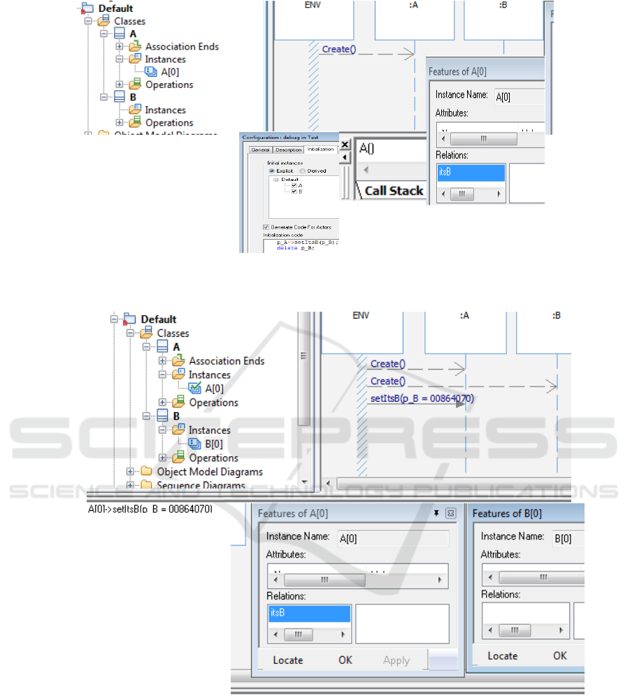
Figure 2: Creation of A[0] with various views: configuration initialization, animated sequence diagram, call stack, instance
features window.
Figure 3: B[0] created, A[0] not yet connected to it. Note connection command in call stack.
remains NULL. Due to the directionality of the
association, the features window of B[0] has no
relations (figure 3).
After an additional step in the animation, setItsB
returns, is popped off the call stack, and the relation
itsB is assigned to B[0] (figure 4).
Figure 5, captures the state of the system after
destruction of B[0]. As expected, the Instances
folder of B is now empty. However, due to the
directionality of the association, the relation itsB of
A[0] remains as before, where non-existent denotes
a dangling pointer, due to destruction of B[0]
4.2 UML Bi-directional Relationships
Consider the two alternatives for achieving bi-
directional relations shown in figure 6. A and B may
be connected by two directional associations (left) or
SKY 2016 - 7th International Workshop on Software Knowledge
48
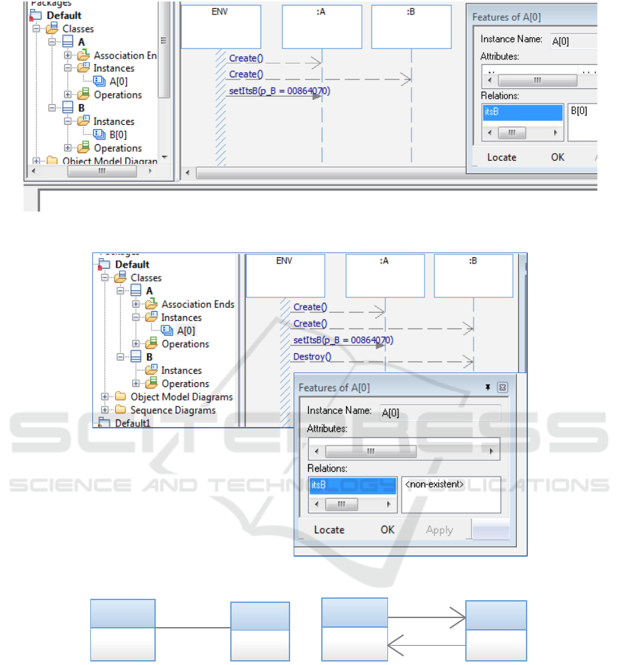
Figure 4: A[0] relation its B connected to B[0].
Figure 5: A[0] dangling pointer.
Figure 6: A and B related by separate directional associations. (left), related by a single bi-directional association (right).
by a single bi-directional association (right). As
before the semantics of each can be explored at the
code and simulation levels.
For the first case, the implementation of the
directional associations is as above in section 4.1.
This implies that if an instance of A is related to an
instance of B, that instance of B can be related to
any instance of A, that is the relation is not
reciprocal. On the other hand , the semantics of the
bi-directional association supports a reciprocal
relationship. If an instance of A is related to an
instance of B, that instance of B is related to that
very instance of A. If the relation of itsB of an
instance of A is then set to a new instance of B, this
new relationship is reciprocal, and therefore the
relationship its A of the first instance of B must be
set to NULL.
As before we explore the semantics of the two
cases via a scenario defined in main. For the first
case, code in main creates two instances of A, and
A
B
1
1
itsB
itsA
A
B
1
itsB
1
itsA
Modeling Semantics sans Mathematical Formalism
49

an instance of B, relates A[0] to B[0] and B[0] to
A[1], rather than A[0].
The input to constructional scenario is the
following code in main:
A * p_A;
B * p_B;
p_A = new A;
p_B = new B;
p_A->setItsB(p_B);
A* p_A1= new A;
p_B->setItsA(p_A1);
The tracer output demonstrates the independence of
the two directional relations:
Please enter OMTracer Command>> go
idle
OMTracer New instance A[0]:A
created by main()
OMTracer New instance B[0]:B
created by main()
OMTracer A[0] Relation itsB set to
B[0]
OMTracer New instance A[1]:A
created by main()
OMTracer B[0] Relation itsA set to
A[1]
Executable is Idle
The corresponding graphical demonstration via
animation is shown in figure 7.
For the bi-directional association case, the input
to the scenario, is the following main code, which
provides the most precise specification of the
constructional scenario:
A * p_A;
B * p_B;
p_A = new A;
p_B = new B;
p_A->setItsB(p_B);
delete p_B;
B* p_B1= new B;
B * p_B2 = new B;
p_A->setItsB(p_B1);
p_A->setItsB(p_B2);
In this scenario an instance of A and B are
created and their reciprocal relationship set to each
other. The instance of B is then deleted, and,
because of the reciprocity requirement, the instance
of A is not left with a dangling pointer, but rather
itsB is set to NULL. Next, two new instances of B
are created. The instance of A is connected to one of
the instances of B.
The intricate semantics of reciprocity, inter-
object relation, requires the detail that only
framework code can provide. (figure 8). A
connection is initiated by calling the function setIts
(B or A).
This function calls the helper function _setIts
(single underscore prefix) which calls the
corresponding helper function on the other side (i.e.,
if the connection is initiated from class A via a call
to setItsB; _setItsB in class A calls _setItsA in class
B, resulting in a recipricol process in which there is
a check as to whether either of the objects to be
connected is currently connected to another object.
If so, the currently connected object is disconnected
by setting its association end pointer to NULL.
The animated sequence simulation of the
aforementioned scenario is shown in figure 9.
Figures 10-11 show the objects and their
connections in the various stages of this scenario.
The animated sequence simulation of the
aforementioned scenario is shown in figure 9.
Figures 10-11 show the objects and their
connections in the various stages of this scenario.
5 DISCUSSION
5.1 Present Status of Research
The examples presented were selected from a
repository including all of the UML structural
relationships and object-oriented statecharts of
varying complexity. The model-level simulations
motivate the practitioner to interactively explore the
software at a model-level of abstraction and gain
insight into the model semantics in a very concrete
manner that speaks to the in-the-trenches
practitioner and encourages buy-in to the enterprise
of model-level semantics.
What is proposed herein is an unconventional
semantic domain to which UML syntax can be
mapped. The mapping is to multiple model-level
views. Ultimately, the as-built semantics is
determined by the implementation code, not of the
application, but rather of the framework
implementing UML. Hence, the inclusion of
framework code in the examples. We emphasize
“as-built” because exploration of the framework
code will reveal widely accepted good practices,
that, although not canonized in OMG UML
documentation, are interpretations that enhance the
state of the art. Two examples presented above: (1)
for well-formed associations of multiplicity 1, object
instantiation should initialize the association end to
SKY 2016 - 7th International Workshop on Software Knowledge
50
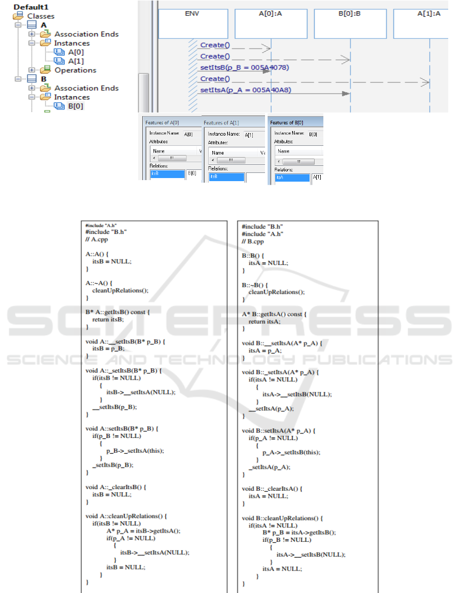
Figure 7: Non-reciprocity: A[0] related to B[0], B[0] related to A[1]. (sequence and instance views).
Figure 8: Automatic code supporting association reciprocity.
Modeling Semantics sans Mathematical Formalism
51
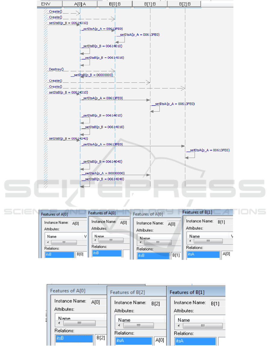
Figure 9: Multiple Object Connections and Reconnections.
Figure 10: (From Left to Right) 1. Connection of A[0] and B[0]; 2. A[0] after destruction of B[0]; 3. A[0] reconnected to
new object B[1].
Figure 11: A[0] connects to B[2] thereby disconnecting B[1].
NULL in a mandatory assignment in the constructor.
(2) A bi-directional association should support a
reciprocal managomous protocol, such that at any
given instant, two objects are linked to each other
SKY 2016 - 7th International Workshop on Software Knowledge
52

(or to no object), replacing previously linked objects,
whose association ends should be assigned NULL.
Visual insight into the as-built semantics is
supported by the various model-level simulation
artifacts, and the practitioner acquires insight by
interrogating the simulated model and examining
these artifacts.
5.2 Underlying Abstractions and
Semantics
The semantic issues herein are illustrated with the
mediation of a specific tool, and with reference with
a specific implemtation language. Nonetheless,
modelling artifacts such as call stacks, instance
feature windows, animated sequence diagrams and
statecharts provide a level of abstraction that the in-
the-trenches engineer can relate to. Furthermore, the
generated code should not be distained as mere
implementation, but rather gives expression to
constructural semantics, and some cases is
interpretive of UML.
The holy grail of a standard and thorough UML
semantics may not be achievable and perhaps should
not be achieved, as different interpretations are
inevitable and viable, provided that within a given
development environment, such as Rhapsody, there
is consistency and closure.
The articulation of these abstractions are
necessarily tool-dependent, and, indeed, other tools
may lend themselves to different abstractions than
those presented herein. In particular, tools that have
been disseminated in industry and have a substantial
user base, tend to absorb by “osmosis” abstractions
that have been effective in practice.
Aside from the issue of standardization, the
author acknowledges that to say that executable
modelling artifacts comprise rigorous model-level
semantics is pushing the envelope of semantics. A
simulation, including model simulation, is an
approximation. Nevertheless, it gives the practicing
engineer a lexicon of visual and textual abstractions
that is close enough to the code (in some cases the
best abstraction is the code itself) but develops a
mind set of abstraction, imparting understanding of
overall system behavior.
5.3 Desideratum
Herein a small subset of UML has been addressed.
To address all the UML “sublanguages” would be
overly ambitious. Nonetheless, extension of the
present work to cover the remaining UML structural
relationships, as well as reactive systems with
statecharts of various topologies may result in
extension and/or modification of the proposed
abstractions/
In a similar vein, comparable work with other
executable modeling tools would be an important
test of the viability of the proposed abstractions: to
what extent are they “universal” abstractions and to
what extent tool-specific.
Executable modeling tools may not be widely
deployed, but nonetheless occupy a significant
market niche. Interviews with practitioner,
unfettered by the pre-conceived notions of this
author, would be an important source of “practical”
abstractions
Another product of such interviews, would be to
explore to what extent model level abstractions
impart understanding of system behavior and instill
enough confidence to rely on production-quality
code generated by a given tool. In this vein, I close
with an anecdote:
I colleague of mine, responsible for development
of an air-borne mission computer, used a modeling
tool for conceptual modeling only, although it
produced reliable production-quality code. I asked
him whether he had ever considered letting the tool
produce his code. At that time, his response was that
he personally wanted to make sure that the code that
had to work at 20000 feet in the air would do what it
is supposed to do. Several years later, he was in fact
letting the tool produce his code, and the difference
was the degree to which he and his staff understood
the model semantics.
ACKNOWLEDGEMENTS
The author wishes to thank Dr. Iaakov Exman, (The
Jerusalem College of Engineering – JCE - Azrieli)
for his helpful and incisive comments.
REFERENCES
Booch, G. (1983) Software Engineering with ADA. 1st
edn. Benjamin/Cummings.
Bowen, J.P. and Hinchey, M.G. (1995) ‘Ten
Commandments of Formal Methods’, Computer,
28(4), pp. 56–63. doi: 10.1109/2.375178.
Bowen, J.P. and Hinchey, M.G. (2006) ‘Ten
Commandments of Formal Methods ...Ten Years
Later’, Computer, 39(1), pp. 40–48. doi:
10.1109/mc.2006.35.
Broy, M. and Cengarle, M.V. (2011) ‘UML formal
semantics: Lessons learned’, Software & Systems
Modeling Semantics sans Mathematical Formalism
53

Modeling, 10(4), pp. 441–446. doi: 10.1007/s10270-
011-0207-y.
Diskin, Z. and Dingel, J. (2006) ‘Mappings, Maps and
Tables: Towards Formal Semantics for Associations in
UML2’, 9th International Conference, MoDELS 2006,
Genova, Italy, October 1-6, 2006. Proceedings, , pp.
230–244.
Evermann, J. (2008) ‘A cognitive semantics for the
association construct’, Requirements Engineering,
13(3), pp. 167–186. doi: 10.1007/s00766-008-0065-5.
Gamma, E., Booch, G., Johnson, R., Vlissides, J.M. and
Helm, R. (1995) Design Patterns: Elements of
Reusable Object-oriented Software. 14th edn.
Reading, MA: Addison-Wesley Professional.
Génova, G. (2001) “Semantics of Navigability in UML
Associations”. Technical Report UC3M-TR-CS-2001-
06, Computer Science Department, Carlos III
University of Madrid, November 2001, pp. 233-251.
Harel, D. and Rumpe, B. (2004) ‘Meaningful Modeling:
What’s the semantics of “semantics”?’,Computer,
37(10), pp. 64–72. doi: 10.1109/mc.2004.172.
Rational rhapsody developer (2016) Available at:
http://www-03.ibm.com/software/products/en/ratirhap
(Accessed: 19 September 2016).
SKY 2016 - 7th International Workshop on Software Knowledge
54
