
Modulaser: A Tool for Conceptual Analysis of Software Systems
Iaakov Exman and Phillip Katz
Software Engineering Dept., The Jerusalem College of Engineering – JCE - Azrieli, POB 3566, Jerusalem, Israel
Keywords: Modulaser, Software Tools, Conceptual Analysis, Conceptual Integrity, Software System Design,
Modularity Matrix, Standard.
Abstract: Modulaser is a software tool which produces a Modularity Matrix, to analyse the design of a software
system given by its executable code. However, besides the concrete practical purposes of Modulaser, it is
important to understand its techniques in a deeper sense. It is immediately clear that it describes the system
in a higher abstraction level than the executable code, as the Modularity Matrix follows an implicit class
diagram. But behind classes there are concepts. Thus, the ultimate purpose of Modulaser is conceptual
analysis. This paper explains the ideas, describe Modulaser in these terms, and illustrate it by a series of
case studies.
1 INTRODUCTION
Modulaser is a software tool to support design
analysis of software systems of any size. It is based
upon Linear Software Models – see e.g. (Exman,
2014a) – i.e. it generates a Modularity Matrix for a
given software system to guide the software
engineer along the software system design and
development.
From a different viewpoint, beyond the linear
algebra techniques, one asks what can be the deeper
meaning of Modulaser. In this paper we point out to
conceptual analysis as a response to this issue. In
particular, we mention conceptual integrity as a
central idea of conceptual design analysis.
In this Introduction section we next clarify the
ideas of software conceptual analysis and concisely
review the basics of the Modularity Matrix.
1.1 Software Conceptual Analysis
Informal conceptual analysis, with the central notion
of conceptual integrity in the context of software,
has been developed initially by Brooks in his book
“The Mythical Man-Month” (Brooks, 1995). It
appears again in (Brooks, 2010), where conceptual
integrity is said to consist of three principles:
orthogonality, propriety and generality of system
functions. The idea has been proposed and praised,
but not exactly defined.
Our basic tenet is that since an ontology is easily
related to an UML class diagram, one can assume
that behind each class of a software system stands a
concept of an implicit application ontology (Exman
and Iskusnov, 2014b).
We have recently suggested initial steps towards
a more precise notion of conceptual analysis
(Exman, 2016). Intuitively, integrity besides being a
property of the whole hierarchical software system,
it should be a recursive property of each of its
subsystems down to basic blocks. It is plausible that
if any subsystem does not have conceptual integrity,
the whole system cannot display it either.
Thus Modulaser enables analysis of a given level
of abstraction – say its classes and methods – and
the next level – say modules – made up of the given
classes and methods.
1.2 Modularity Matrix
The Modularity Matrix – see e.g. (Exman, 2012a,
2012b, 2014a) is a representation of a hierarchical
software system in its several abstraction levels,
through sub-systems, down to indivisible basic
modules.
The matrix columns, the structors, stand for
architectural structure units – a generalization of
classes. The matrix rows, the functionals, stand for
architectural behavioural units – a generalization of
class methods.
A standard Modularity Matrix is square and
block diagonal, where the blocks along the diagonal
are the modules of the current matrix level.
In case there still are outliers, non-zero matrix
Exman, I. and Katz, P.
Modulaser: A Tool for Conceptual Analysis of Software Systems.
DOI: 10.5220/0006080700190026
In Proceedings of the 7th International Workshop on Software Knowledge (SKY 2016), pages 19-26
ISBN: 978-989-758-202-8
Copyright
c
2016 by SCITEPRESS – Science and Technology Publications, Lda. All rights reserved
19

elements outside the block-diagonal modules, these
elements highlight problematic couplings among the
modules. These couplings should be resolved by
moving/removing/adding structors and or
functionals, in the columns/rows containing the
outliers.
1.3 Related Work
Conceptual analysis of software – be it design,
structure or other aspects – can be roughly divided
into two camps. The first one, with a rather informal
approach, exemplified by Brooks – see e.g. (Brooks,
1995) – and authors that either accepted and
developed his ideas or struggled to clarify them.
In the first camp there are works that explicitly
refer to Conceptual Analysis, in particular
Conceptual Integrity. Most of them formulate some
vague qualitative statement of its meaning.
Kazman and Carriere in a Technical Report
(Kazman, 1997) describe how to reconstruct a
software system architecture. They are guided by
Brooks’ conceptual integrity. The architecture
should be built from a small number of components
connected in regular ways, with consistent allocation
of functionality to the architecture’s components.
Clements et al. in (Clements, 2001) refer to
conceptual integrity as the theme that unifies the
design of a system at all levels. The architecture
should do similar things in similar ways, having a
small number of data and control mechanisms, and
patterns throughout the system. Note the language
similarities between Kazman (“connected in regular
ways”, “small nmber of components”) and Clements
(“do similar things in similar ways”, “small number
of control mechanisms”), both somehow
reproducing Brooks’ ideas of “propriety” and
“generality”, which are principles behind conceptual
integrity.
The second camp, much more formal, identified
the word “conceptual” with some rather developed
theory, such as FCA (Formal Concept Analysis)
which uses the Conceptual Lattice as its basic
algebraic structure. An example of this second camp
is Cole and Tilley (Cole, 2003) which analysed
software structure by means of Conceptual Lattices.
See also (Exman and Speicher, 2015) and references
therein.
Another group of works refers to software tools
to support software systems analysis and design. For
instance, (Kazman, 1996) describes a SAAMtool,
with a visualization capability, which is somewhat
different from that of Modulaser. SAAMtool
displays a sort of components diagram. In contrast,
Modulaser indeed has a dependency graph, but it is
mainly an intermediate stage for the central
representation by a Modularity Matrix.
One should also mention that besides the
Modularity Matrix, other matrices, e.g. the DSM
(Design Structure Matrix) have been used in the
context of software systems design. DSM is part of
the Design Rules approach (Baldwin and Clark,
2000). Despite the “Matrix” name, these matrices
are rather tables with presence/absence of marks,
mainly used without numerical values.
1.4 Paper Organization
In the remaining of the paper we introduce the
software architecture of the Modulaser tool (section
2), describe Modulaser’s functionality and user
interface (section 3), provide concise pseudo-codes
of the algorithms inside Modulaser, used to build
and analyse the Modularity Matrix (section 4),
discuss a series of case studies as a demonstration of
the Modulaser usage (section 5), shortly describe the
implementation approach (section 6) and conclude
with a discussion (section 7).
2 MODULASER’S SOFTWARE
ARCHITECTURE
Here we shortly describe the Modulaser software
architecture principles and the main Modulaser
modules.
2.1 Software Architecture Principles
The main principles behind the Modulaser software
architecture are:
1. Central Information Storage – the
separation of the information storage from
specific functionalities enables future
additions of different kinds of input: for
example system input files in various
programming languages and environments;
2. Central Program Manager and specific
functional modules – the separation of the
program manager from modules similarly
enables later additions/replacements of
more efficient algorithms.
2.2 Main Modulaser Modules
Modulaser’s architecture is shown in Fig. 1.
SKY 2016 - 7th International Workshop on Software Knowledge
20
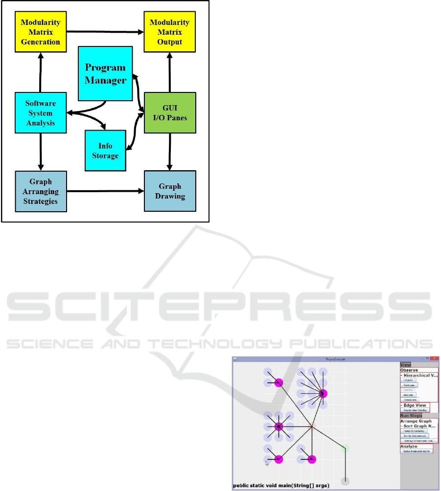
Figure 1: Modulaser Schematic Software Architecture –
Its modules are: a- GUI input/output in the right hand side;
b- Program manager and central info storage in the
middle; c- Software System Analysis and specific
functionalities in the left hand side: Modularity Matrix
modules (in yellow), graph modules (in light blue).
Arrows point to receiver of data transmitted.
The main Modulaser modules – schematically
shown in Fig. 1 – are:
1. Program Manager – serves as a master
controller for the Modulaser;
2. Info Storage – is the place where input and
intermediate results are stored for
processing;
3. Software System Analysis – contains the
algorithm and procedures to analyse the
desired software system;
4. GUI I/O Panes – contain panes to receive
input and buttons to control processing and
display;
5. Modularity Matrix modules – generate and
display the Modularity Matrix of the
software system under analysis;
6. Graph modules – generate and display, for
each module of the software system under
analysis, a dependency graph among
classes and respective functions.
Further details about these modules are provided
in the next sections.
3 MODULASER’S FUNCTIONS
AND USER INTERFACE
In this section we overview of the Modulaser main
functionalities and its user interface.
3.1 Functionality
The two main functionalities of the Modulaser tool
are related to the software “System under Analysis”
(SUA) classes and respective methods: generation of
the Dependency Graph and the corresponding
Modularity Matrix. These two representations
provide different information on a SUA.
A dependency graph, for a given version of the
“Game of Life”, is seen in a Modulaser screen-print
in Fig. 2. A dependency graph is a directed graph
linking classes within a package and methods within
a class in “evaluation” order.
The Modulaser dependency graph enables
focussing on a chosen type of entities: packages,
classes or methods. In Fig. 2 the focus is on classes.
The corresponding Modularity Matrix, for the
same “Game of Life” is shown in Fig. 3. The Matrix
columns – the structors – stand for the classes and
the Matrix rows – the functionals – stand for the
methods. The Modularity Matrix has 1-valued
matrix elements when a given “structor” (class)
provides a certain “functional” (method). In Fig. 3
the 1-valued elements are shown in green color.
Figure 2: Game Of Life: Dependency Graph – The
dependency graph of a version of the Game of Life, in the
left-hand pane of this screen print, highlights 5 classes –
represented by filled circular nodes (purple color) – and
their respective methods – linear segments outgoing from
the classes. For instance, the upper-left class has 2
methods. The main class, is the dependency graph root.
Modulaser: A Tool for Conceptual Analysis of Software Systems
21
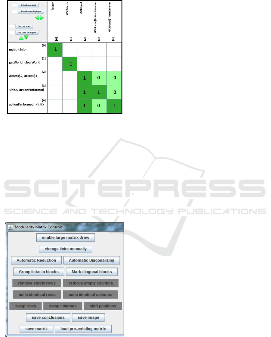
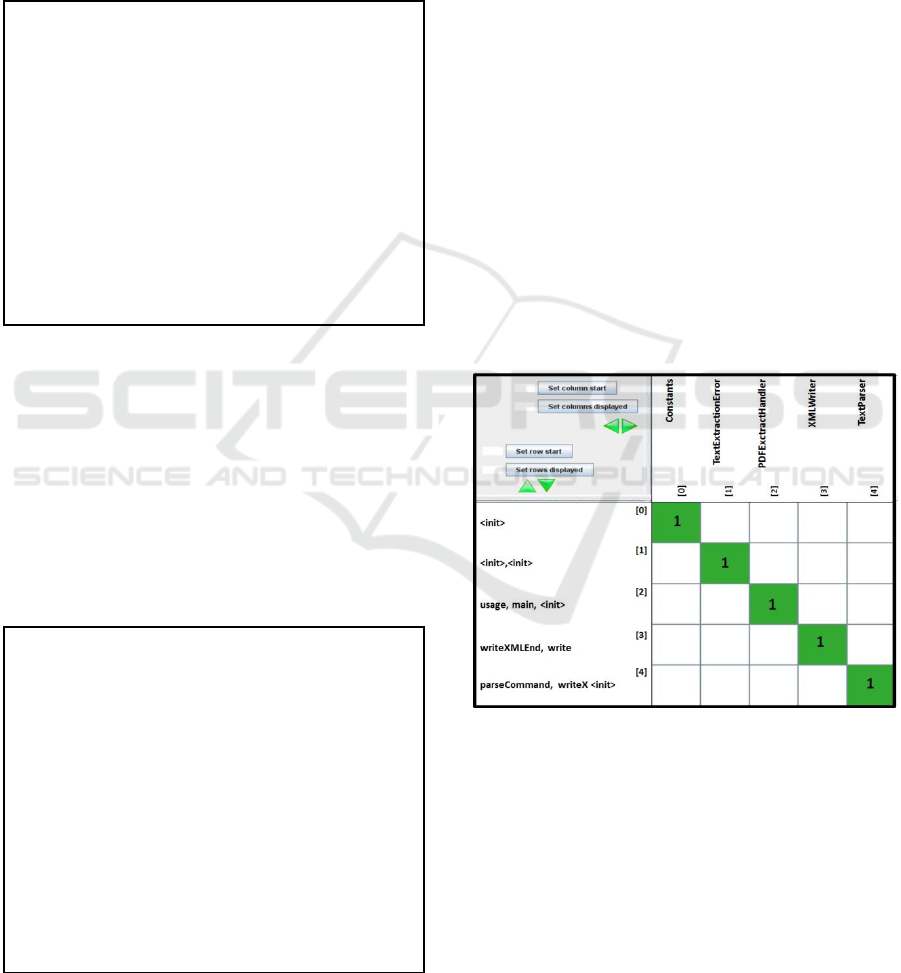
Figure 3: Game Of Life: Modularity Matrix – The
Modularity Matrix of the Game of Life in Fig. 2. The
matrix columns – the “structors” – are classes; the matrix
rows – the “functionals” – are methods. For 1-valued
matrix elements a “structor” provides the respective
“functional” (in darker green). The sub-matrix in rows
([2], [3], [4]) is the “Game of Life Panel” Module. It has
zero-valued elements (in lighter green). All other matrix
elements (white) have their zero-valued elements omitted.
3.2 User Interface
The Graphical User Interface (GUI) is composed of
floating windows and panes inside the windows. The
Modularity Matrix controls are seen in Fig. 4.
Figure 4: Modularity Matrix Controls – There are buttons
to perform automatic actions (as block diagonalization),
specific actions on the Matrix (as remove empty rows) and
post-processing actions (as save conclusions).
The commands in the Modularity Matrix controls
(in Fig. 4) can be classified into three types:
Automatic – one can decide to let the
Modulaser perform a complete action without
user intervention, as block diagonalization of
the Matrix;
Local – the user takes direct control and
decides about specific local actions, such as
“removing empty columns”;
Post-Processing – one may save the Matrix or
the conclusions from the analysis.
We have seen in Figures 2 and 3 embedded
panes with commands relevant to other panes in the
same window. In Fig. 2 the right-hand pane has
buttons to control variables and appearance of the
dependency graph.
In Fig. 3 the upper-left pane enables the user, in
case the matrix is very large, to choose how many
columns/rows to display, and from which
columns/rows start the display. This can be done
either by filling-in character slots, or by clicking
arrow-head (triangular) buttons (in green).
4 MODULASER ALGORITHMS
The Modularity Matrix is the central algebraic
structure of Modulaser. In this section we refer to
the algorithms whose final purpose is
“Modularization”, i.e. to find the Modules in the
next hierarchy level of the given matrix.
4.1 Modularity Matrix Algorithms’
Ideas
Within Modulaser the modules of a given matrix are
found in two phases:
1. Dependency Clustering – to find which
columns and respective rows belong in the
same cluster of linear dependence;
2. Clusters Sorting – once the clusters were
found, we need to rearrange the matrix to
display clusters (the final Modules) as sets
of consecutive columns and respective
rows, without intersections of clusters.
The basic idea is to assign to every row and to
every column a “sticky cluster”. The “sticky-cluster”
is an object which maintains a pointer to a collection
of sticky-clusters, where each collection member
points back to the collection.
SKY 2016 - 7th International Workshop on Software Knowledge
22
Rows/columns with the same “sticky cluster” can
be merged into a larger cluster. Merging causes
redirection of the new members to the newly-
enlarged collection.
4.2 Dependency Clustering Algorithm
A pseudo-code of the dependency clustering
algorithm is shown in the next text-box.
The complexity of the for loops is O(#rows) and
O(#columns), while that of the merging operation is
O(smaller-cluster size). The typical running time is
not large relative to the matrix size, since Modularity
Matrices are supposed to be sparse by fundamental
reasons, i.e. Modularization success brings the
design to Modules with no couplings among them.
4.3 Cluster Sorting Algorithm
A pseudo-code of the cluster sorting algorithm is
shown in the next text-box.
The complexity of the for loops is O(#rows) and
O(#columns), while that of the move operation is
O(1), as it involves only swapping places with
relevant row/column.
5 CASE STUDIES
The case studies in this section go from the simplest
case – a strictly diagonal matrix – to a few much
larger and more complex software systems that have
been analysed.
5.1 A PDF-to-XML Converter
The PDF-to-XML Converter is a simple tool whose
Modularity Matrix (in Fig. 5) is strictly Diagonal,
i.e. all the structors (and functionals) are mutually
orthogonal (a characteristic of conceptual integrity!).
Besides a trivial Constants class, the concepts
(classes) in this tool are self-explanatory:
PDF Extract Handler – a main program;
Text Parser – to parse commands;
XML Writer – to write and end writing;
Text Extraction Error – to deal with
eventual errors.
Figure 5: PDF-to-XML Converter Modularity MATRIX –
It displays the Smiley above a platform and below another
one, a series of platforms, a menu button on top-right and
a restart button on top-left.
5.2 Xonix Game
The Xonix Game is a much larger software system,
with a Modularity Matrix of size 97*97 seen in Fig.
6. This Modularity Matrix is so large that the class
and function names are not readable. Nonetheless,
even in this small scale, it enables appraisal of its
general appearance, which is clearly block-diagonal.
Cluster Sorting Algorithm
//Initialize Matrix
Matrix = clustered Modularity Matrix (the
outcome from the previous algorithm);
Create “dummy” row/column in index 0;
//Rearrange, while scanning Matrix
For each sticky cluster{
For all columns in the cluster{
Move column to index_0;}
For all rows in the cluster{
Move row to index_0;}
}
Delete “dummy” row/column in index 0;
Dependency Clustering Algorithm
//Initialize sticky groups
Matrix = initial Modularity Matrix;
For all rows and columns{
Assign “sticky group” to each row
and column};
//Merge sticky groups, while scanning Matrix
For all rows{
For all columns{
If (Matrix[row][column] = 1-valued){
mergeClusters(col cluster, row cluster)
}}}
Modulaser: A Tool for Conceptual Analysis of Software Systems
23
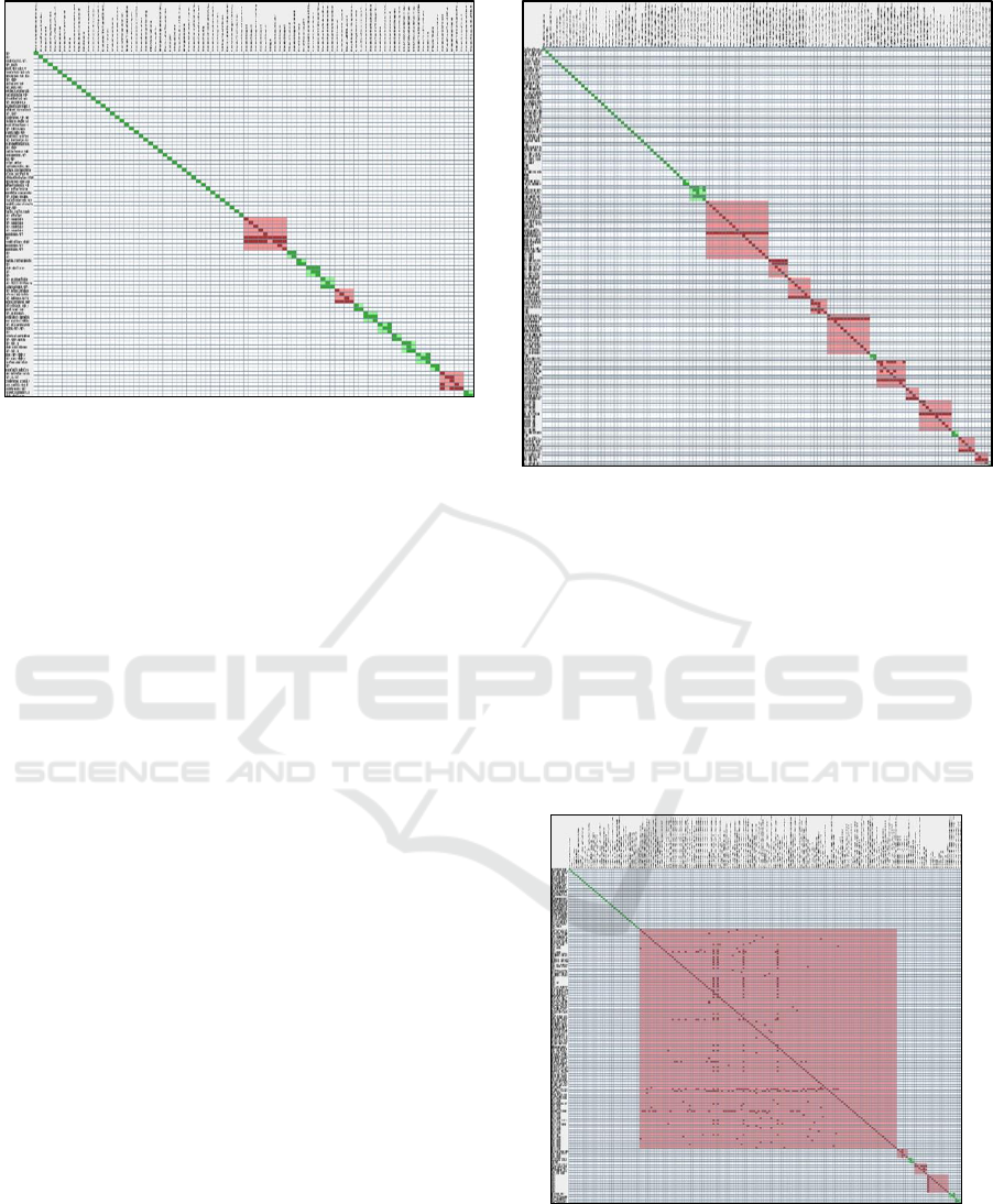
Figure 6: Xonix Game Modularity Matrix – This is a
block-diagonal Matrix of size 97*97. It has 3 biggest
Modules (in red and pink color) which are not standard, as
their sparsity is bigger than expected for a Module. There
are 12 Modules (in green and light green color) which are
block diagonal and standard. The remaining blocks are
strictly diagonal.
In contrast to a whole Modularity Matrix,
Modules should be non-sparse – see e.g. (Exman,
2015). This is not true for all Xonix modules.
The Xonix Game Modularity Matrix (in Fig. 6)
has only 3 larger Modules which are non-standard,
i.e. they are sparser than expected for a normal
Module. Otherwise, the matrix modules, with sizes
between 3*3 and 2*2, have normal sparsity. Finally
there are many one-by-one strictly diagonal
modules.
Analysis of this Matrix identified duplicate code
problems in: different game stages; input from the
keyboard; panel definitions.
5.3 An Apache Library
Apache is a well-known set of open source programs
with a variety of purposes, one of them being the
well-known Apache HTTP server. Here we obtained
the Modularity Matrix of an Apache Library.
The Modularity Matrix, of size 143*143, seen in
Fig. 7, has similar characteristics to the Xonix Game
Matrix in Fig. 6. Overall, it is block-diagonal but the
number of relatively large modules with greater than
desired sparsity increased to 10 modules.
It can be easily seen that each of the larger
problematic modules essentially have a single row
full of 1-valued matrix elements in an otherwise
strictly diagonal submatrix. This is most probably
easily solvable, by decoupling the problematic row.
Figure 7: Apache Library Modularity Matrix – This is a
block-diagonal Matrix of size 143*143. It has 10 bigger
Modules (in red and pink color) with sparsity is bigger
than expected for a Module. There are 3 Modules (in
green and light green color) which are block diagonal and
standard. The remaining blocks are strictly diagonal. One
easily sees in the larger problematic submatrices, a single
coupling row on top of a strictly diagonal structure.
5.4 An Android Application
The Android Application has a Modularity Matrix of
size 185*185, in Fig. 8.
Figure 8: Android Application Modularity Matrix – This is
a Matrix of size 185*185. It has a single very sparse
problematic largest Module, covering more than half of
the matrix columns/rows. Otherwise, the matrix is similar
to the previous ones.
SKY 2016 - 7th International Workshop on Software Knowledge
24

The Android Application matrix is distinctively
different from the previous ones. It displays a single
very sparse problematic Module, covering more than
a half of the Modularity Matrix columns/rows.
This can be attributed either to the matrix
describing an intermediate development stage or to
the design requirements enforced by the Android
operating system. This has been observed in more
than one such application. Its conceptual analysis is
obviously incomplete deserving further
investigation.
6 MODULASER SOFTWARE
IMPLEMENTATION
In this section we provide some details of the
Modulaser system implementation.
Modulaser was implemented in the Java
language, totally anew, except for the use of the
Apache BCEL library (BCEL, 2016).
BCEL (Byte Code Engineering Library) enables
reading binary Java class files, obtaining the
information about each class, such as inheritances
and class methods.
Modulaser uses BCEL to read the Java class files
of the software System Under Analysis, and stores
the information read into the Info Storage.
7 DISCUSSION
This discussion encompasses foundational issues,
practical considerations and future work. It is
concluded with a short statement of the main
contribution.
7.1 Foundational Issues
The deeper motivation behind Modulaser is to
provide a tool for conceptual analysis of software
systems under development or already in a
maintenance phase.
The following issues deserve to be taken into
account:
a. Conceptual Analysis
It is based on the assumption that “structors”, i.e.
either classes or their generalization (say design
patterns) correspond to concepts in a higher
abstraction level. Thus, one implicitly assumes the
existence of an application ontology – see e.g.
(Exman and Iskusnov, 2014b) – with the specific
concepts of the software system. Such an ontology,
if well-constructed, is expected to guarantee
Conceptual Integrity, which is a complex
foundational issue per se. Since Integrity probably
cannot be assumed to be assured, its analysis should
follow from the Modularity Matrix characteristics.
b. Software Systems of any size
This is an important issue, with respect to
“structors”, the generalization of classes to any
hierarchical level. Modulaser only reflects the
entities directly defined in the programming
language syntax, such as classes, interfaces,
packages, methods, etc. Since to go upwards in the
hierarchical abstraction levels transcends the
language syntax, – e.g. by referring to design
patterns (Gamma, 1995) – this requires an
innovative approach.
7.2 Practical Considerations
The main question here is to which extent can be
Modulaser be actually used in practice, in particular
during development of a software system.
The following issues deserve further attention:
System Size – we have successfully applied
Modulaser to a variety of software systems
with different and increasing sizes, as has
been shown in the Case Studies of this
paper. Success refers to efficiency
parameters as running time and memory
consumption.
Scalable Zooming Characteristics – an
important characteristic of a tool applicable
to software systems of very different sizes
is the ability to rapidly obtain information
in various zooming scales. Modulaser has
been useful in this respect too. One can
obtain an overall view of the system (say
with unreadable class names), and then
decide to zoom into particular classes to
obtain detailed information needed for
redesign.
7.3 Future Work
Some of the open issues deserving development and
further investigation are described here.
The input to Modulaser consisted up to now to
software systems that are themselves originally
written in Java. It is clearly desirable to enable input
of programs in diverse languages, such as C++, C#,
Ruby, etc. The current Modulaser architecture,
Modulaser: A Tool for Conceptual Analysis of Software Systems
25

which is modular, should support these new
additions.
Transcending the limitations of programming
language, operating system and running
environment, to climb the hierarchy of abstraction
levels is a challenge that was already mentioned
among the foundational issues.
7.4 Main Contribution
The main contribution of this work is the description
and proof of feasibility of Modulaser as a practical
tool for software conceptual design analysis.
REFERENCES
Baldwin, C.Y. and Clark, K.B., 2000. Design Rules, Vol.
I. The Power of Modularity, MIT Press, Cambridge,
MA, USA.
BCEL, 2016. Byte Code Engineering Library, version 6.0,
An Apache Commons Project. Web site:
https://commons.apache.org/proper/commons-bcel/
Brooks, F.P., 1995. The Mythical Man-Month – Essays in
Software Engineering – Anniversary Edition,
Addison-Wesley, Boston, MA, USA.
Brooks, F.P., 2010. The Design of Design: Essays from a
Computer Scientist, Addison-Wesley, Boston, MA,
USA.
Cole, R. and Tilley, T., 2003. “Conceptual Analysis of
Software Structure”, Proc. 15
th
Int. Conf. on Software
Engineering and Knowledge Engineering, pp. 726-
733.
Clements, P., Kazman, R, and Klein, M., 2001. Evaluating
Software Architecture: Methods and Case Studies.
Addison-Wesley, Boston, MA, USA.
Exman, I., 2012a. “Linear Software Models”, Proc. GTSE
1
st
SEMAT Workshop on a General Theory of Soft-
ware Engineering, KTH Royal Institute of Techno-
logy, Stockholm, Sweden.http://semat.org/wp-con-
tent/uploads/2012/10/GTSE_2012_Proceedings.pdf.
Exman, I., 2012b. “Linear Software Models”, video
presentation of paper (Exman, 2012a) at GTSE 2012,
KTH, Stockholm, Sweden, Web site: http://www.you
tube.com/watch?v=EJfzArH8-ls.
Exman, I. 2014a. “Linear Software Models: Standard
Modularity Highlights Residual Coupling”, Int.
Journal of Software Engineering and Knowledge
Engineering, Vol. 24, pp. 183-210, DOI: 10.1142/-
S0218194014500089.
Exman, I. and Iskusnov, D., 2014b. “Apogee: Application
Ontology Generation from Domain Ontologies”, in
Proc. SKY’2014 Int. Workshop on Software
Knowledge, pp. 31-42, ScitePress, Portugal.
Exman, I. and Speicher, D., 2015. “Linear Software
Models: Equivalence”, in Proc. ICSOFT’2015 Int.
Conference on Software Technology, pp. 109-116,
ScitePress, Portugal. DOI = 10.5220/0005557701090
116
Exman, I., 2016. “The Modularity Matrix as a Source of
Software Conceptual Integrity”, SKY’2016 7
th
Int.
Workshop on Software Knowledge, Porto, Portugal,
accepted for publication.
Gamma, E., Helm, R., Johnson, R. and Vlissides, J., 1995.
Design Patterns: Elements of Reusable Object-
Oriented Software, Addison-Wesley, Boston, MA,
USA.
Kazman, R., 1996. “Tool Support for Architecture
Analysis and Design”, in ISAW’96 Proc. 2
nd
Int.
Software Architecture Workshop, pp. 94-97, ACM,
New York, NY, USA. DOI: 10.1145/243327.243618
Kazman, R. and Carriere, S.J., 1997. “Playing Detective:
Reconstructing Software Architecture from Available
Evidence.” Technical Report CMU/SEI-97-TR-010,
Software Engineering Institute, Carnegie Mellon
University, Pittsburgh, PA, USA.
SKY 2016 - 7th International Workshop on Software Knowledge
26
