A State Transition Model for Business Processes
Towards Object-oriented Business Process Automation
Anantharamaiah Prabhakar
Enterprise Flow Technosoft Services Pvt. Ltd., Bangalore, India
Keywords: Business Process Modelling, Business Process Design, Human Centric BPM.
Abstract: This paper develops a new model for business processes, called State Transition Model. According to this
model, a business process instance starts in some state, then flows, not necessarily sequentially, through zero
or more intermediate states, until it is terminated in one of the states. The State Transition Model isolates the
workflow part of a process from the non-workflow parts. The State Transition Model facilitates object-
oriented design of business processes. It results in a top-down approach to human-centric business process
automation. This is in contrast to the popular BPMN model, which results in a bottom-up approach.
1 INTRODUCTION
Business process automation is the strategy an
organization uses in order to reap one or more of the
following benefits:-
Improved operational efficiency
Reduced turnaround times
Consistency of business activities
Reduced errors
Reduced operating costs
Process automation methodologies should ideally
enable integration of existing proven software
applications, or third-party software, in order to avoid
“re-inventing the wheel”, as well as to reduce the
associated development costs.
Automation of a given business process typically
begins with a process model (Havey, 2005; Aalst,
2009; Weske, 2007; Object Management Group,
2011). It is usually a BPMN model, which appears to
be a defacto industry standard.
2 STATE TRANSITION MODEL
In this paper, we propose a State Transition Model for
business processes. Our model is quite different from
that proposed by Huang (Huang, 1998), in which a
process is modelled as a collection of states, with each
task, or activity, represented by one state, and several
types of transitions between states.
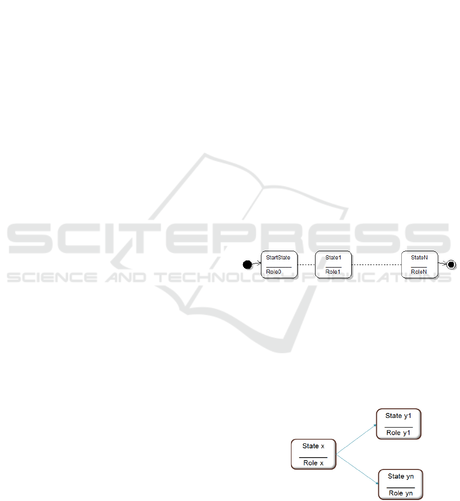
According to our model, a business process starts
in a state, called StartState, then flows, not
necessarily sequentially, through zero or more
intermediate states, until it is terminated in one of the
states. In each state, a corresponding role performs
one or more activities. (See Figure 1).
Figure 1: State Transition Model.
Note: A business process instance can
simultaneously be in more than one state, pending
activities to be performed by the corresponding role
players (actors). This can happen due to parallel
workflow. Shown in Figure 2 is a process that can
simultaneously be in States y1, …, yn, since it flowed
simultaneously, i.e., in parallel, from State x to States
y1, …, yn.
Figure 2: Parallel Workflow.
Prabhakar, A.
A State Transition Model for Business Processes - Towards Object-oriented Business Process Automation.
DOI: 10.5220/0006074302710276
In Proceedings of the 8th International Joint Conference on Knowledge Discovery, Knowledge Engineering and Knowledge Management (IC3K 2016) - Volume 3: KMIS, pages 271-276
ISBN: 978-989-758-203-5
Copyright
c
2016 by SCITEPRESS – Science and Technology Publications, Lda. All rights reserved
271
3 STATE TRANSITION MODEL
DEVELOPMENT
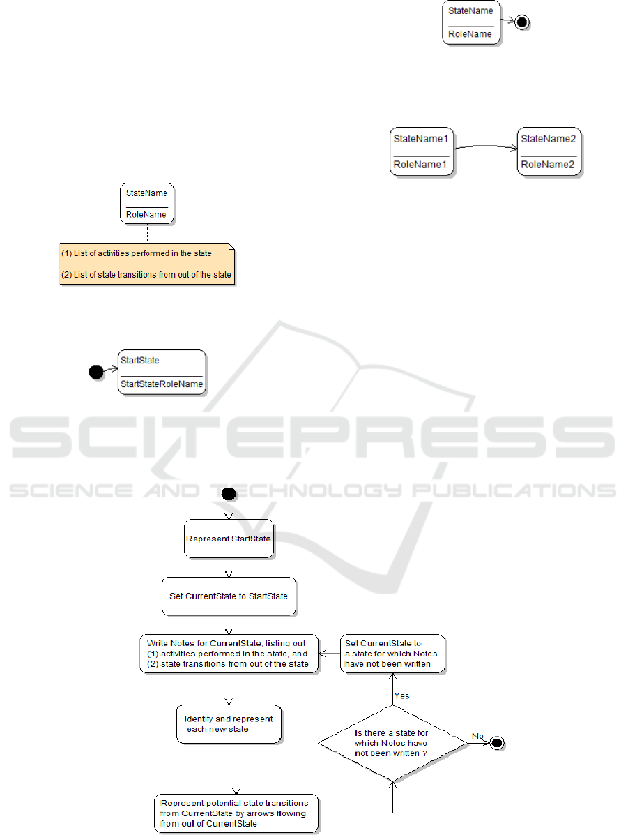
Each state is represented by a rounded rectangle. (See
Figure 3). The name of the state, and the name of the
role, are shown within the rounded rectangle.
Attached notes list out
1. The activities performed in the state, and
2. The state transitions from out of the state.
Figure 3: State Representation.
StartState is represented as shown in Figure 4.
Figure 4: StartState Representation.
A state in which the process can be terminated is
represented as shown in Figure 5.
Figure 5: Process Termination.
An arrow from one state to another represents a
potential state transition (See Figure 6).
Figure 6: Potential State Transition.
A flow chart for developing a State Transition
Diagram is shown in Figure 7.
To create State Transition Diagrams, you can use
any State Diagramming Tool, e.g., Violet UML
Editor, a free download from https://sourceforge.net/
projects/violet/.
4 EXAMPLE: LEAVE
APPLICATION PROCESS
The employees of an organization (e.g., a
corporation) can go on leave only after due approval.
One of the employees plays the role of HRManager,
who is the final authority to approve leave. Typically,
Figure 7: Flow Chart for Developing a State Transition Diagram.
KMIS 2016 - 8th International Conference on Knowledge Management and Information Sharing
272
every employee has a Supervisor; however, there are
a few senior employees who do not have Supervisors.
In case an employee has a Supervisor, the latter’s
approval is also required for going on leave.
Leave Application Process is as follows:-
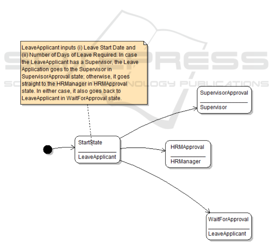
LeaveApplicant starts the process by inputting (i)
Leave Start Date, and (ii) Number of Days of
Leave Required. In case the LeaveApplicant has
a Supervisor, the Leave Application goes to the
Supervisor; otherwise, it goes straight to
HRManager.
Supervisor either approves, or disapproves, the
Leave. If he / she approves, the Leave
Application goes to the HRManager; otherwise,
it returns to the LeaveApplicant.
HRManager either approves, or disapproves, the
Leave. In either case, the Leave Application
returns to the LeaveApplicant.
LeaveApplicant terminates the process.
5 DISCUSSION
The State Transition Model enables us to treat a
business process instance as an object belonging to
the business process instance class. The object always
gets created in the StartState of the process under
consideration. Thereafter, the object may make one or
more state transitions. At some instance of time, the
object can simultaneously be in more than one state.
Finally, the object may get destroyed while in some
state(s).
The State Transition Model does not model the
activities performed in each state. These activities do
not involve workflow; techniques for modeling such
activities are by now well established, notably UML
(Rumbaugh, 2004).
The State Transition Model also models only the
potential state transitions. The conditions under
which each state transition takes place are not
modeled. This is because, typically, the conditions
will involve values of data in a database; therefore,
Leave Application Process – StartState is shown in Figure 8.
Figure 8: Leave Application Process - StartState.
A State Transition Model for Business Processes - Towards Object-oriented Business Process Automation
273
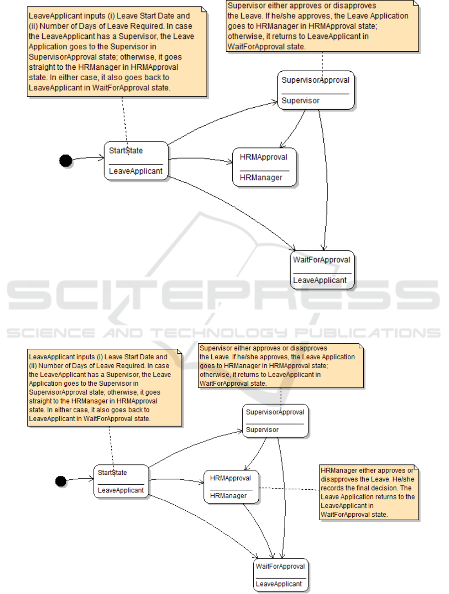
Leave Application Process – SupervisorApproval state details are added on, and shown in Figure 9.
Figure 9: Leave Application Process - SupervisorApproval.
Leave Application Process – HRMApproval state details are added on, and shown in Figure 10.
Figure 10: Leave Application Process - HRMApproval.
KMIS 2016 - 8th International Conference on Knowledge Management and Information Sharing
274
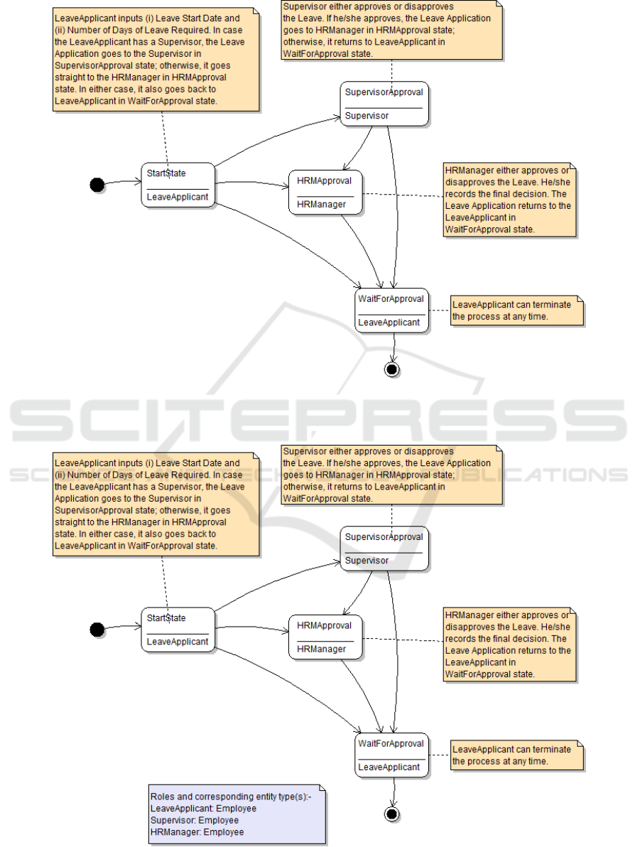
Leave Application Process – WaitForApproval state details are added on, and shown in Figure 11.
Figure 11: Leave Application Process - WaitForApproval.
The final Leave Application Process – State Transition Model is shown in Figure 12.
Figure 12: Leave Application Process – State Transition Model.
A State Transition Model for Business Processes - Towards Object-oriented Business Process Automation
275

modeling these conditions is deferred to the coding
phase.
6 FROM MODEL TO PROCESS
AUTOMATION SOFTWARE
The author has developed a technique for developing
the process automation software in the Java language,
starting from the State Transition Model (Please see
EnterpriseFlow User Guide – Part 7 in
EnterpriseFlow_DBaaS_Kit.zip, downloadable from
http://www.enterpriseflow.com). It is found that the
states in the model directly map to key software
artefacts, viz., one pre-defined, customizable, JSP
template corresponding to each state. Developing
non-workflow software corresponding to the
activities performed in each state, and invoking the
same from the corresponding state’s JSP, or invoking
third-party software from a state’s JSP, are
straightforward.
The procedure for developing the process
automation software starting from a BPMN model
can be found elsewhere. (Dumas, 2013). It will be
seen that this is a bottom-up approach, since software
development commences after detailed BPMN
modelling. On the other hand, the State Transition
Model approach turns out to be a top-down approach.
REFERENCES
Havey, M., 2005. Essential Business Process Modelling,
O’Reilly. Sebastopol, CA.
Aalst, W., Hee, K., 2009. Workflow Management: Models,
Methods, and Systems, PHI Learning. New Delhi.
Weske, M., 2007. Business Process Management:
Concepts, Languages, Architectures, Springer-Verlag.
Berlin.
Object Management Group, 2011. Business Process Model
and Notation (BPMN): Version 2.0, OMG. Needham,
MA.
Huang, S.S., 1998. Building Business Processes Using a
State Transition Model on World Wide Web. In
Proceedings of IEEE Workshop on Application-
Specific Software Engineering and Technology, pp.2-7.
Rumbaugh, J., Jacobson, I., Booch, G., 2004. The Unified
Modelling Language Reference Manual, Addison-
Wesley, 2
nd
edition.
Dumas, M., La Rosa, M., Mendling, J., Reijers, H., 2013.
Fundamentals of Business Process Management,
Springer-Verlag. Berlin.
KMIS 2016 - 8th International Conference on Knowledge Management and Information Sharing
276
