
Differential GNSS for Outdoor Sports -
Testing of Applicability for Alpine Sports
Johan Samuelsson
1
, Magnus Karlsteen
1
and Christian Finnsgård
1,2
1
Centre for Sports and Technology, Dept. of Physics, Chalmers University of Technology, Gothenburg, Sweden
2
SSPA Sweden AB, Research, Gothenburg, Sweden
Keywords: GNSS, Positioning, Tracking, Alpine Sports, GPS, Wearable Technology.
Abstract: The purpose of this paper is to evaluate a differential GNSS (global navigation satellite system) tracking
technology and whether it can be applied in alpine sports. Wearable technology is a technology undergoing
extensive development. Wearable technology is an umbrella term for technology that can be worn,
providing the user with different kinds of information. In sports, this is often related to performance of
athletes. This paper is evaluating a tracking technology and whether it can be applied in an alpine
environment, tracking both cross country skiers as well as down hill skiers. The technology applied in the
product is a DGNSS, a differential Global Navigation Satellite System, a high accuracy positioning
technology. The GNSS is using several satellite systems, providing coverage at all times. The differential
part comes from the use of an accurately surveyed reference station, providing the rover with correction
signals and thereby give a higher accuracy on tracking data. The technology shows promising results in
accuracy in the measurement method used, but needs further evaluation using continuous measurements.
1 INTRODUCTION
GNSS stands for global navigation satellite system
that allows the user to measure position, velocity and
local time in a highly accurate way. The global
navigation satellite system’s signal consists of a
variety of satellite systems in space that broad- cast
navigation signals. The navigation signals can in its
turn be picked up by a GNSS receiver on the earth to
determine that receiver’s position and velocity.
GNSS is useful in navigational applications and
provides fairly accurate position (2.5 metres) and
velocity (0.03 metres/second). A GNSS receiver
must have a clear signal from at least 4 satellites to
function. GNSS satellite signals are weak and
struggle to penetrate through buildings and other
objects obstructing view of the sky. GNSS can also
occasionally drop out due to disturbances in the
upper atmosphere. The GNSS used in this test is a
differential GNSS (or DGNSS). The differential
GNSS is using a reference station with an accurately
calibrated position. The reference station is installed
temporarily on a known position, and calculates
correction parameters and sending them to the
mobile GNSS rover. This technology results in a
reduction of the deviation of the measured position
to the actual position of the GNSS user receivers
(Granby, 2016).
The technology can be applied to several areas
outside of sports. The areas of applications include
for instance such as surveying, flying unmanned
aerial vehicles, robotics, marine applications, and
motor sports.
1.1 Problem
A television production company has expressed a
wish for more information and data on the athlete’s
performance, to complement their sports event
productions. This is to provide the end user with
additional value information and providing the
television companies with services that are giving
the production company an advantage over other
production companies. The linking of positioning
data and live video-feed is considered as extra
difficult to achieve. An increase in the precision in
the positioning will provide additional features
possible to combine with the viewer experience, and
is thus desirable.
GNSS positioning technology can be applied to
gather information on the athlete’s position, velocity
188
Samuelsson, J., Karlsteen, M. and Finnsgård, C.
Differential GNSS for Outdoor Sports - Testing of Applicability for Alpine Sports.
DOI: 10.5220/0006055701880196
In Proceedings of the 4th International Congress on Sport Sciences Research and Technology Support (icSPORTS 2016), pages 188-196
ISBN: 978-989-758-205-9
Copyright
c
2016 by SCITEPRESS – Science and Technology Publications, Lda. All rights reserved

and acceleration in both team sports and individual
sports. In an application in an alpine skiing
environment, demands are put on the positioning
technology’s performance in accuracy. It should also
allow large capturing volumes of data in order to be
able to analyse the run. The positioning device
should not restrict in motion or cause discomfort for
the tracked athlete in motion, putting demands on
the size of the device.
The problem to be solved is to track and position
athletes in different contexts, providing athletes,
coaches, and spectators with data. The data can be
used by athletes and coaches to understand what
improvements that can be made or as an escort for
visually impaired athletes. The data can also be used
to create a surplus value in sporting events for the
spectators. The extra information that can be elicited
can be used both for live spectators and for
television broadcasting of sports. Extra data that can
be provided to the audience is the trajectory of the
slope, exact positions during the race, choice of line,
velocity and acceleration (
Spörri et al., 2014).
An evaluating and testing of the product is
desirable (for different sports and accuracy) to what
needs to be improved and if the technology will be
meeting the requirements put on it.
1.2 Present DGNSS Research
In alpine skiing, testing and research carried out are
using the differential GNSS for time measurements
and force measurements. The differential GNSS that
often are used in these contexts are often expensive
and well calibrated and not built for applications
where athletes are carrying it with them. In the
research where differential GNSS are used, it is for
proving the technology and accuracy of other
positioning devices.
In research where athletes actually have carried
the differential GNSS, the research performed have
shown promising results in using the differential
GNSS for time measurements in both alpine skiing
as well as 100 m sprints. In the 100 m sprint a
regular GNSS was tested and the results in the time
measurements were compared to the data from a
photocell. The study proves that regular GNSS can
be used for time measurements of smaller segments
of a slope. The technology could also be used for
deciding on location comparisons between the
athletes. The researchers also finds data that can be
used for professional athletes and their coaches to
analyse training and competition performance.
(Advanced Navigation, 2015).
Similar tests have been made using a differential
GNSS to measure the trajectories of slopes and
make time measurements with a regular GNSS to
compare to the time measurements of photocells.
Also in this study, tests proved that the data
provided by the GNSS gives an applicable time
measurement method and will provide better
opportunities for analysing the ride than from just
the use of photocells for measurements (Murray,
2014).
Low cost GNSS using lower sampling
frequencies have shown not to be appropriate for
tracking and time measuring. This goes for devices
using a sampling rate of 1 Hz or lower. The reason
for this is the distance travelled changes too much
during the sampling time (Mercator, 2016).
The differential GNSS is also often used as a
reference value when testing other positioning
devices in surveying. The differential GNSS used in
these cases are using real time kinematics (RTK)
that provides high accuracies close to a base station.
Real time kinematics uses a reference station and an
open channel for broadcasts information in real time.
With this information, the rover equipment is able to
fix the phase ambiguities and determine its location
relative to the base with high precision (Advanced
Navigation, 2016).
What can be said overall by the current research
is that not many providers on the market are testing
and using differential GNSS for measurements. The
technology is still under development and is
considered expensive and ungainly to wear in sports
and is not yet considered wearable technology.
1.3 Purpose of the Paper
From the above background and described problems,
the purpose of this paper is to evaluate a differential
GNSS tracking technology and whether it can be
applied in alpine sports.
1.4 Outline of the Paper
The paper describes an evaluation a differential
GNSS tracking technology and whether it can be
applied in alpine sports. The paper is divided as
follows: Section 1 introduces the problem
background, current research and the purpose of the
paper. Section 2 provides the theoretical framework.
Section 3 describes the method used in the study,
followed by Section 4, addressing the results.
Section 5 progresses into the discussion of the
results. Finally, Section 6 will summarise the
contributions made in the paper.
Differential GNSS for Outdoor Sports - Testing of Applicability for Alpine Sports
189
2 THEORETICAL FRAMEWORK
Satellite based positioning is the determination of
positions of observing sites. Satellites provide the
user with the capability of determining a position
expressed by for instance latitude, longitude and
height.
Latitude and longitude can be described as the angle
between where the object is positioned and the
reference axis. For latitude, the reference axis is the
equator. For longitude, the reference meridian is the
international prime meridian. This way, every
location on earth can be specified by a set of
numbers. Latitude is specified as the lateral positions
on a spherical shape, and the longitude as the
vertical positions on a spherical shape. The latitude
and longitude is measured in degrees or radians. The
altitude that needs to be used when specifying
positions is measured in meters over the reference
ellipsoid WGS84, a model used for approximating
sea level across the Earth (Hofmann-Wellenhof et
al., 2008).
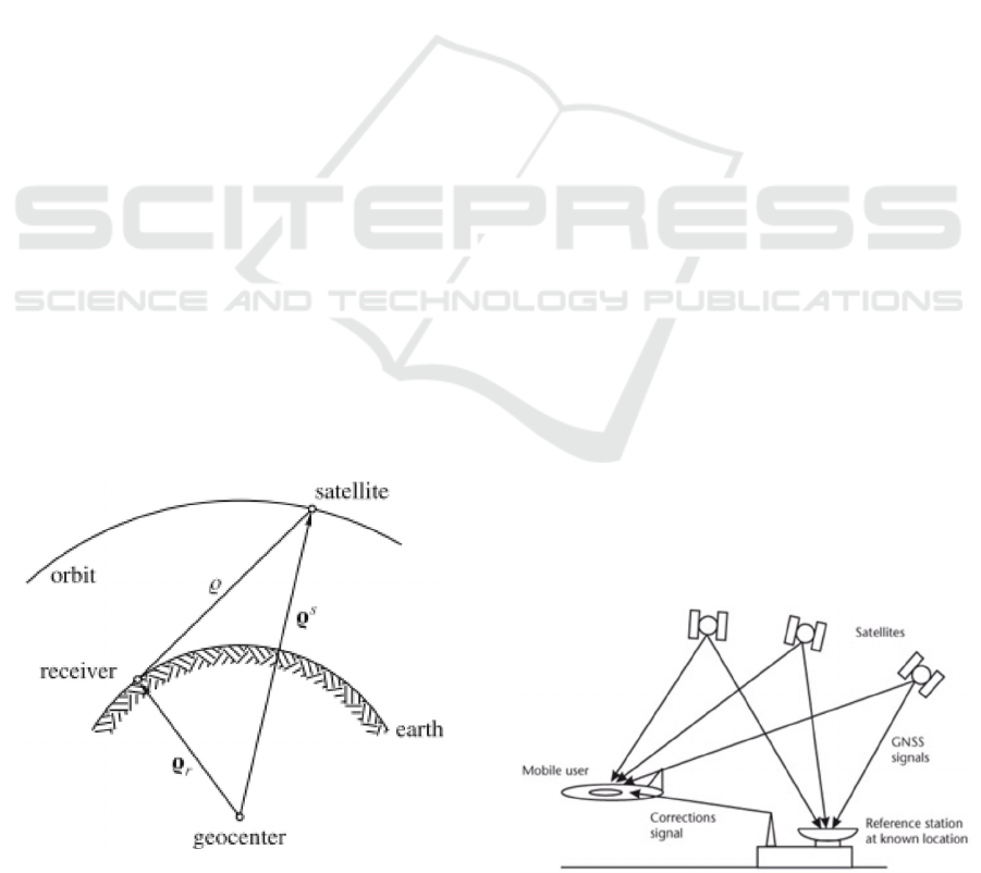
The process for positioning something with
latitude, longitude and elevation is done by a
resection process, where range differences measured
to satellites are used, see figure 1. To relate this to
what is happening, the vector Q
s
relates to the center
of the earth (geocenter) of each satellite. The
geocentric position of the receiver on the ground is
defined by the vector Q
r
and is set to system time.
The geometric distance Q to each satellite could be
measured from recording the time required for the
satellite signal to reach the receiver. Using this
technique would yield in the unknowns, latitude,
longitude, and elevation, that could be determined
from the three range equations Q = ||Q
s
− Q
r
||.
(Hofmann-Wellenhof et al., 2008).
Figure 1: Principle of satellite based positioning
(Hofmann-Wellenhof et al., 2008).
2.1 Global Navigation Satellite Systems
The most oldest and most common GNSS system is
the American Global Positioning System (GPS).
Other GNSS systems are the Russian system
GLONASS, the European Union system Galileo,
and the Chinese system Beidou. GNSS satellites
orbit the earth at about 20,000 km altitude. Each
GNSS system has their own constellation of
satellites, providing the system with desired
coverage.
GNSS stands for global navigation satellite
system and consists of a number of satellites in
space that broadcast navigation signals. The
navigation signals can in its turn be picked up by a
GNSS receiver on earth to determine that receiver’s
position and velocity. GNSS is useful in
navigational applications and provides fairly
accurate position (2.5 metres) and velocity (0.03
metres/second). A GNSS receiver must have a clear
signal from at least 4 satellites to function. GNSS
satellite signals are weak and struggle to penetrate
through buildings and other objects obstructing view
of the sky. GNSS can also occasionally drop out due
to disturbances in the upper atmosphere.
2.2 Differential GNSS
The GNSS used in this test is a differential global
navigation satellite system (DGNSS). Differential
GNSS is an enhancement to a primary GNSS, using
a reference station with a accurately surveyed
position. The method takes advantage of the slow
variation with time and user position of the errors
due to ephemeris prediction, residual satellite clocks,
ionospheric and tropospheric delays. Starting from
the reference station the system broadcasts
corrections to the GNSS rover, see figure 2. The
rover needs to be enabled for receiving correction
signals and be connected to the same satellite as the
reference station in order to function (GMV, 2011,
Hofmann-Wellenhof et al., 2008).
Figure 2: System overview of a differential GNSS.
icSPORTS 2016 - 4th International Congress on Sport Sciences Research and Technology Support
190
This technology results in a reduction of the
deviation of the measured position to the actual
position of the GNSS user receivers. The reference
station has the technical possibility to position itself
using different satellite systems, which leads to a
more accurate position. Variations of the technology
exist, where multiple reference stations are used,
leading to a higher accuracy for the rover. This
technology can be applied in order to cover a larger
area, using reference stations strategically placed in
order to have coverage on the correction signals.
2.3 Data Processing
When processing the data coming from the units, the
error and standard deviation needs to be expressed in
an easy comparable unit. The unit of choice was
meters, to get a physical translation that is relatable.
This yields for transformations of the data.
According to Advanced Navigation, their procedure
was to do the transformation to Earth Centered Earth
Fixed (ECEF) (Orr, 2016).
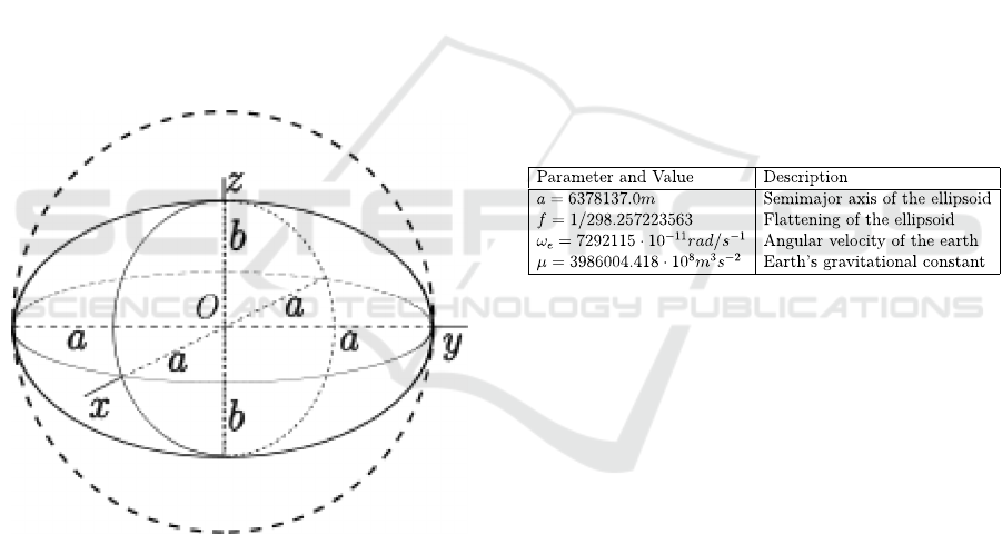
Figure 3: A sphere of radius a compressed into ellipsoid.
This format is useful in calculation of Cartesian
coordinates when using a non- spherical form.
Converting in to Cartesian coordinates and considers
the earth as a sphere will yield in a systematic error
in the measurements, as the earth is not spherical,
see figure 3. This means that if calculating with
Cartesian coordinates and using the same radius for
all of the earth would yield in different errors at
different locations. Using ECEF conversion the earth
is considered an elliptical shape and the flattening of
the earth will be considered in the calculations. The
Cartesian coordinates calculated will have its origo
in the center of the earth. The geodetic coordinates
will be transformed from latitude and longitude into
X and Y coordinates while the altitude will be added
to the Z-component to get the altitude and the
change thereof. The altitude of the Z-component will
be expressed in meters above the reference ellipsoid.
World Geodetic System 1984 (WGS84) is a
terrestrial reference frame, a reference ellipsoid. The
reference ellipsoid is a mathematically defined way
of describing the surface of a geoid. Associated with
this frame is a geocentric ellipsoid of revolution,
originally defined by the parameters a, f, ω
e
and μ,
see table 1. WGS84 is globally considered accurate
within 1 meter (Hofmann-Wellenhof et al., 2008).
Using the Matlab command LLA2ECEF from
the aerospace toolbox, the geodetic coordinates
latitude, longitude and altitude where converted into
ECEF-format in meters. The LLA2ECEF command
is using WGS84 as default ellipsoid. The input
arguments for LLA2ECEF is [degree, degree,
meters], which is fitting for the data set that is
provided by the DGNSS examined (Statista, 2016).
Table 1: Parameters of the WGS-84 ellipsoid.
3 METHOD
In this section the research methodology is
described. The data collection design together with
data handling is described.
The measurement method where made with
accurately surveyed positions were calibrated on flat
ground and in a ski slope.
The flat ground testing was performed on
Vallhamra sports facilities (Sweden) and the ski
slope of choice was located in Ulricehamn
(Sweden).
By doing post-processing calculations using
Matlab and Microsoft Excel, the latitude, longitude
and altitude can be translated into meters.
The used points were accurately surveyed using
hired technology from Leica.
The surveyed points were then put on the form
fitted for comparison with the data points from the
tested product. By hiring the technology a reference
value could be established, and thereby minimize
sources of errors in reference.
Differential GNSS for Outdoor Sports - Testing of Applicability for Alpine Sports
191

By putting the GNSS antenna in the zigzag
pattern and allowing it to collect 180 samples the
point is considered accurately surveyed and the
position is known with 3mm + 0.1 ppm accuracy.
The tests carried out on Vallhamra sports
facilities where replicated in a slope at Ulricehamn
ski center. The proceed was the same using hired
technology from Leica to survey points in the slope,
marking out these and thereafter make a run on skis,
wearing the devices mounted on top of the helmet.
3.1 Data Collection
When processing the data coming from the units, the
error and standard deviation needs to be expressed
Physical testing have been performed on flat ground
and in a slope. The flat ground tests were performed
for getting a value where accuracy could be
calculated. This accuracy was then applied on the
tests in the ski slope as a proof of concept. The tests
were made with regard to finding absolute accuracy
and the relative accuracy. To get a value of the
absolute accuracy, accurately surveyed points on a
plane surface is being marked out using a levelled
Leica Viva GNSS GS14 together with a hand held
Leica CS20. Here the exact position can be
compared to the value from the GNSS unit. The
accurately surveyed points on the sport arena were
placed in a zigzag pattern. The points were marked
using orange spray paint and thereafter visited one at
a time. By holding the GNSS over the point for five
seconds, a visual trigger was provided for the post-
processing of data, providing the possibility to see
where the points are.
3.2 Data Analysis
Both the flat ground tests and the tests performed in
a ski slope were made using a calibrated starting
point and then 4 other points in a zigzag pattern. The
points are calibrated with the Leica Viva GNSS
GS14 mounted in the point, using averaging for 160
cycles, and thereafter marked out, using an orange
spray paint. The collection of data was made after
calibrating points. After this the devices where hand
held and walked across the field. At each point the
device was held still for five seconds to mark the
position in data. This yielded, with a sample rate of
20 Hz, 100 samples at the position, making it
possible to read out from the data sheet. By plotting
the data, an estimation of at what sample the
position is marked. This sample number is then
translated from its (latitude, longitude, altitude)-form
to an earth centered, earth fixed, ECEF-form. This
will yield in a format of the coordinates and the
movement can be given in a form of a regular
coordinate system (X, Y, Z). The movement given in
ECEF-form will then be used for creating a mean
value around the turning point. The mean value is
calculated around the minimal difference value
using 90 samples. From these values a standard
deviation and mean error for the accuracy was
calculated.
Investigating the accuracy between two devices
was made by putting two or more units on a fix
distance between the units. Here the recorded
distance can be compared to the actual distance. This
testing was only performed on flat ground. The
testing was performed using a plank attached to a
bicycle holder in the back of a car. This car was then
driven around a running track. The two units
attached to the plank were then observed and the
distance between them, 188 cm, could be observed
how it differed from the reality. From this data the
standard deviation and mean error can be calculated.
The recording of the distance between the devices is
made by using a plugin for the program recording
the data. Gmap.net and
mapprovider.projection.getDistance are the plugins
and functions that are used by the program.
4 RESULTS
For the flat ground test with calibrated points the test
was made using two different trackers. The data was
processed separately from that data set and thereafter
analysed. The accurately surveyed latitude and
longitude will be denoted CALLAT and CALLON.
The values used around the turning points when
doing the tests are denoted lat and the mean value
around that point is denoted ∆lat and ∆lon.
The columns ECEF means that the values have
been converted from lat, lon, alt into earth-centered
earth-fixed, ECEF-form. This was done using
Matlab and converts an input of ([rad], [rad], [m])
into ([m], [m], [m]). The Matlab code uses the
following values for WGS84 ellipsoid constants
(National Imagery and Mapping Agency, 2004). The
final column Diff is simply the difference between
the calibrated value and the mean value around the
turning point. This is the same as the distance from
the calibrated point (Table 2).
For tracker 2 the RMS values for the different
positions were 0.5274, 0.36026, 0.11289, 0.53633,
and 0.484 meters for each point. This results in a
standard deviation of 0.1773 m.
icSPORTS 2016 - 4th International Congress on Sport Sciences Research and Technology Support
192
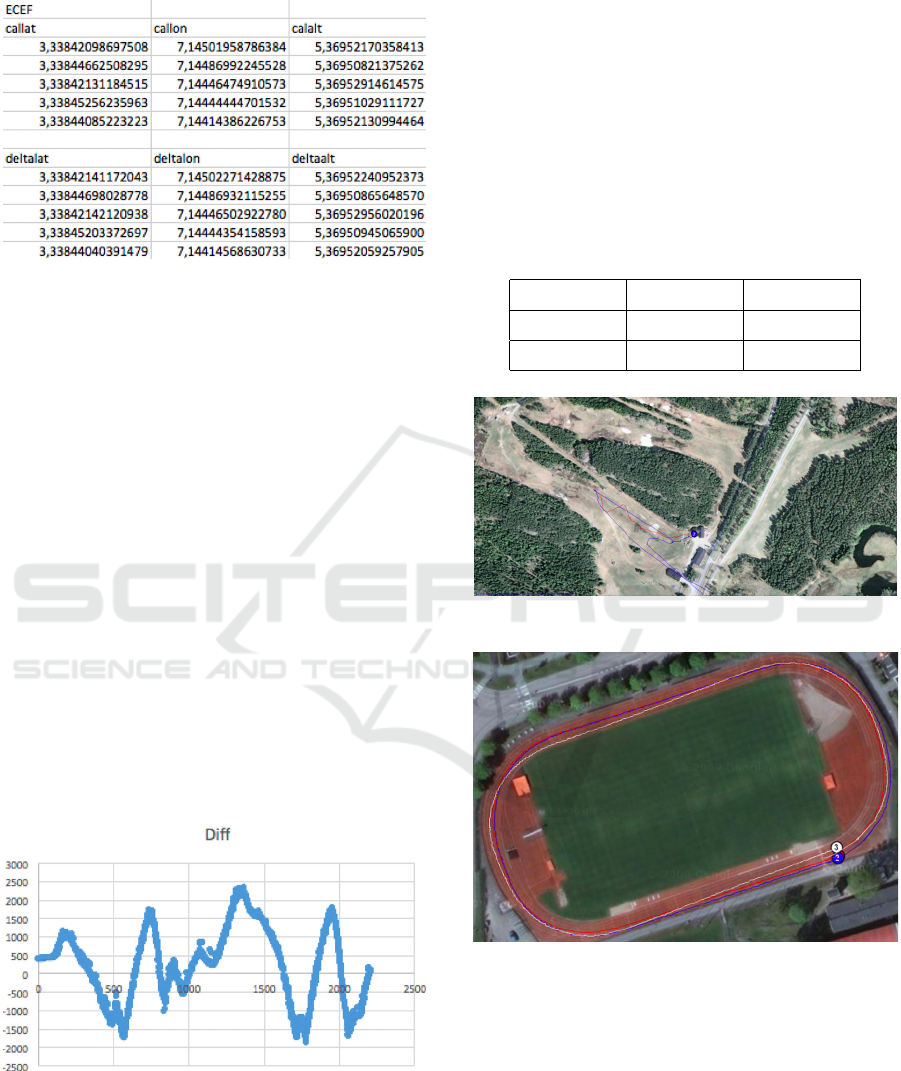
Table 2: ECEF values for tracker 2 at Vallhamra [m].
For tracker 3 the RMS values for the different
positions were 0.0768, 0.3877, 0.5563, 0.9203, and
0.4331 meters for each point. This results in a
standard deviation of 0.3053 m.
Tests on relative positioning error was also made
by putting two devices on a fix distance between
them and then driven around a running track with a
car. The physical distance between the devices was
1880 mm and in figure 4 the fluctuations in
difference can be seen over the 2200 samples.
The calculations from this gives a standard
deviation of 1.003 m, a mean value of 0.215 mm and
fluctuating values between -1.877 m and 2.321 m.
This means that mean of the two trackers results
in a standard deviation of 0.2413 m (Table 3). So,
with 68% certainty the data retrieved from the
tracking device is within a span of 0.2413 meters of
the observed position. With 95 % certainty the data
from the tracking device the device is within a span
of 0.4826 m of the observed position. With 99.7 %
certainty the data from the tracking device the
device is within a span of 0.7239 m of the observed
position.
Figure 4: Positioning error, distance [mm] between two
units over sample number [n].
Physical testing in the intended environment of
use was also made. This was made as a proof of
concept, that the device can be used for tracking an
alpine skier. In figures 5 and 6, a red and a blue line
can be observed. These lines are both representing a
rover carried by a skier. The red line is following the
track that was surveyed. The blue line is an other of
the rover, that drifted away and did not provide any
results of use. When riding the lift up for the ski
slope test, the connection was lost when going up
the lift and the devices needed to be restarted. After
this, the data collection could proceed and in the
peaks, the turns can be observed.
Table 3: Standard deviation of the measurements from
Vallhamra IP.
Figure 5: Run from ski slope in Ulricehamn.
Figure 6: Measurements from Vallhamra sports facilities.
5 DISCUSSION
The data collected, the collection method and the
handling of the data will be discussed. Along with
this, problems that manifested themselves during the
tests will be discussed. Technical outcomes from the
testing will be discussed.
1‡ 2‡ 3‡
68% 95% 99.7%
0.2413 m 0.4826 m 0.7239 m
Differential GNSS for Outdoor Sports - Testing of Applicability for Alpine Sports
193

5.1 Discussion of Measurements
After some research on methods of how to translate
the data available, it was decided to take the
approach using accurately surveyed points. Holding
the rovers laying flat in the palm of the hand, the
accurately surveyed points were marked one at a
time by holding the rover still for five seconds.
Mean error and standard deviation was than
calculated by taking the difference between this
point and the points close to the point. This could
yield in a better accuracy than reality, since the data
collection was allowed to run while being close to
the point. When calculating the mean error in this
case, the measurement is assumed to reach a steady
state with close to zero error. Therefore the outcome
from these results should be approached with
caution as they might leave a too promising
prognosis.
The accuracy from the tests was better than
expected. As earlier stated, the accuracy should be
approached with caution, as the method is not
verified. It is hard to further discuss whether the
accuracy is good enough or not, regarding what
requirements and future areas of use into a value to
aim for.
After performing the tests it was found that the
calibration of altitude should have been made before
commencing the collection of data but was not made
properly which resulted in a systematic error of 5.4
meters. This calibration is made with regard to the
height above the ground that the reference station is
put. This was handled when doing the post
processing of the data. The calculations were per-
formed with the systematic error subtracted in order
to not affect the data. The subtraction was made in
order to get a proper value of the altitude
measurements, as these are important when
measuring in a ski slope.
The values on the relative positioning error was
not as good as expected. Earlier measurements
performed by a company had shown more promising
results. The reason for this could be that there have
been a problem with getting a differential fix
between the reference station and the devices,
something that was experienced during the tests.
Earlier tests have shown standard deviations and
mean errors that were more in the range of 0.7 m
and 0.003 m in mean error according to the company
contact. This method of testing should however be
considered to be discarded. To calculate the error
between two unsure sources should not be
considered as a scientific way of proving
performance for a product like this. The way errors
occur for two rovers among them can be random and
if interference of the satellite signal occurs, it will do
so for both of them, causing unreliable results.
It is important outcome from the testing in the
ski slope, is that when connection is lost for the
device it is crucial to restart it and allow it to get a
differential fix before commencing the tests.
Reasons for the blue line in figure 5 can be because
of this problem. The rover has failed to get
differential fix and the collected data is useless. The
problem can also have appeared because of
problems with the software causing multi-path
errors. After the study, a software update has been
performed, targeting a number of weaknesses. A
follow up study showed considerably better results.
Alternative methods for measuring are present.
The most used method is continuous measurements
using a calibrated differential GNSS. Post
measurements data processing then needs to be
made using Matlab or software such as Justin from
Javad, where one can evaluate data from two
different input sources in double differential mode.
In a comparison of cost between choosing to go with
Matlab versus investing in Justin it differs 2800 SEK
between getting Justin from Javad. Matlab 18500
SEK + aerospace toolbox 9500 SEK = 28000 SEK
versus Justin from Javad 30800 SEK. (Javad, 2016,
Matlab, 2016).
The method using accurately surveyed points put
demands on post processing data handling that was
time consuming. The time consumption is not in
parity with the power of the results, as the method is
not verified when evaluating GNSS accuracies. This
is an other reason for investing in software for
facilitate quick evaluations of future updates in the
product.
The tests showed that the units where non robust
to rotation, something that caused the unit to loose
the differential fix. This needs to be evaluated in a
future requirement specification whether it will be a
problem when using.
6 CONCLUSIONS
Wearable tech is an expanding market and the rate
of emerging companies is high.
The similar products in the segment are many.
Ranging from GPS watches to ungainly differential
GNSS, the competition is extensive. By getting a
differential, wearable GNSS to show stable results, it
would be a completely new segment of tracking and
positioning devices. The wearable technology, using
differential GNSS with an accuracy that could pose
icSPORTS 2016 - 4th International Congress on Sport Sciences Research and Technology Support
194

a threat to this product has chose to direct their
development focus towards virtual reality products.
It should be kept in mind that this kind of
technology is growing in many different areas of
technology and more spread.
By specifying what the product is going to be
used for, whether it is time measurement, line choice
of the skiers or measurements of velocity, etcetera.
The recommendation for the company when
pursuing the market of differential GNSS tracking of
athletes, is to standardize their testing method. Since
the product has not yet reached its final technology
and the implementation of real time kinematics, it
should be considered favourable to have a
standardized method for testing where
improvements can be confirmed. The standardized
method needs to be created in order to be able to
process data in a reasonable way where
improvements can be easily recorded. When using a
standardized method, it will also be easier to
evaluate the different settings and additional
functions that are available in the technology.
The next step when reaching a prototype that is
reaching the requirements for the product and testing
in different environments and possible sources of
error and most favourable conditions for testing. The
technical possibility for switching between antennas
is already implemented but not yet evaluated and
should therefor also be evaluated. This will be vital
to provide signal range for a full ski slope or a cross-
country ski slope.
At present there are several factors with the
devices that are not making it robust enough for
using. Tilting of the devices, calibration of height
over the ground and loss of differential fix when put
in a skip zone are all problems that is pointing
towards an unfinished product. These findings
should be put in the requirements specification if
they pose a threat to a functioning problem. The
earlier these problems can be resolved, the cheaper it
can be fixed rather than having to do late changes in
product development process.
6.1 Recommendations
When performing future accuracy evaluations, a
reference track should be used in order to
continuously evaluate updates. By having a
consistency in the evaluation method, the evaluation
gets reliable. The creation of the reference track
should be made simultaneously with the data
collection of the differential GNSS. There are two
reason for this, to be able to synchronize the data
sets and to ensure that the circumstances of the earth
is the same for the two different data sets.
When performing tests, it is important to make
everything at the largest extent possible, replicable.
Therefore it is suggested to use the same algorithm
for the process every time.
Other factors that might affect the measurements
that should be considered when collecting data are
the following:
• Collect data in clear weather in order to
ensure satellite coverage. Cloudy skies
might prohibit signal coverage.
• Collection of data to be analysed should be
made continuously, instead of around
accurately surveyed points.
• The rovers needs to be restarted and get
differential fix before commencing data
collection.
• The rovers must be carried with the right
side up, and with the correct side in front.
The rovers should not be rotated over 40
degrees in order to not loose contact with
the reference station.
• The reference station needs to be calibrated
in height over ground every time when
performing tests. This is important to
remember, otherwise it will result in a
systematic error in the altitude
measurements, something that is important
to do as accurate as possible when tracking
alpine skiers.
ACKNOWLEDGEMENTS
The authors wish to acknowledge the support from
New Century Information AB, with Bengt Julin,
Anders Yttergård and Klas Öberg. And Västra
Götalandsregionen via Regionutvecklingsnämnden
for financial support.
REFERENCES
Advanced Navigation (2015), Spatial,. URL
http://www.advancednavigation.com.au/product/spatia
l#applications. Accessed: 2016-05-26.
Advanced Navigation (2016) Spatial,. URL
http://www.advancednavigation.com.au/product/spatia
l#documentation. Accessed: 2016-05-30.
Bernhard Hofmann-Wellenhof, Herbert Lichtenegger, and
Elmar Wasle. GNSS – Global Navigation Satellite
Systems. Springer-Verlag Wien, 2008.
Differential GNSS for Outdoor Sports - Testing of Applicability for Alpine Sports
195

GMV (2011) DGNSS fundamentals,. URL http://www.
navipedia.net/index.php/DGNSS_Fundamentals.
Accessed: 2016-05-12.
Granby, P. (2016) Unpublished MSc. Thesis, Chalmers
University of Technology
Javad. Justin, (2016). URL http://www.javad.com/jgnss/
products/software/justin.html#. Accessed: 2016-06-05.
Matlab (2016). Pricing and licensing aerospace toolbox,.
URL http://se.mathworks.com/pricing-licensing/
index.html?prodcode=AT&s_iid=main_pl_AT_tb.
Accessed: 2016-06-05.
Mercator, P. (2016). Leica viva gs14 – gnss smart
antenna,. URL http: //leica-geosystems.com/products/
gnss-systems/smart-antennas/leica-viva-gs14.
Accessed: 2016-05-16.
Murray, S., (2014) Putting wearables into context with
low-power GNSS, URL http://www.broadcom.com/
blog/wireless-technology/putting-wearables-into-
context-with-low-power-gnss/. Accessed: 2016-05-09.
National Imagery and Mapping Agency (2004) World
geodetic system 1984. Technical Report NIMA
TR8350.2, Department of Defense.
Orr. X., (2016) Nci sports tracker project - the road
ahead... unpublished company material.
Statista (2016) Big data market size revenue forecast
worldwide from 2011 to 2026 (in billion U.S. dollars).
http://www.statista.com/statistics/254266/global-big-
data-market-forecast/. Accessed: 2016-02-29.
Spörri J., Limpach P., Geiger A., Gilgien, M., and Müller
E. (2014) The effect of different global navigation
satellite system methods on positioning accu- racy in
elite alpine skiing. Sensors, 14 (10), 18433-18453.
icSPORTS 2016 - 4th International Congress on Sport Sciences Research and Technology Support
196
