
3D Interactive Environment Applied to Fencing Training
Carla P. Guimarães
1
, Vitor Balbio
1
, Gloria L. Cid
1
, Maria Isabel V.Orselli
3
, Ana Paula Xavier
2
,
Augusto Siqueira Neto
2
and Sônia C. Corrêa
2
1
National Institute of Technology, Rio de Janeiro, Brazil
2
LACEM, Presbyterian University Mackenzie, São Paulo, Brazil
3
Franciscan University, Rio Grande do Sul, Brazil
Keywords: 3D Digital Platform, Biomechanics, Eye Tracking, Fencing, Training.
Abstract: The purpose of this study was to present a 3D interactive environment - a Digital Platform to help in fencing
training. The first fencing motion described and analysed at the 3D platform was lunge in epee fencing. The
platform was able to show kinematic variables of upper and lower limbs and the center of mass that
characterized a good performance in epee fencing. The platform also incorporates a digital database of eye
track motions of the fencers. An OptiTrack motion capture system was used to capture the lunge motion of
five skilled amateur fencing athletes in the presence or not of a static opponent and an Eye Track System
Tobbi II was used to track the eye movements of the fencers when performing a lunge attack with a target.
The 3D platform was developed using Unity3D and can present some interesting results to improve
available information to coaches. That highlights the importance of visualization biomechanical results
based on coach criteria in a more understandable way to help athletic training.
1 INTRODUCTION
It is interesting to appoint that there is a big gap
between scientific knowledge and coaches. It
happens all over the world. There is a lot of
knowledge being developed in the labs but it does
not reach the coaches. The languages are very
different. The coach usually does not understand the
graphics and data that the biomechanics researchers
generate and the coaches need something that they
really can use in their daily practice. We intend to
work in this gap, trying to fulfill the coaches’ needs
but bringing the precision and reliable data that we
can provide.
The use of interactive system is interesting and can
fill this gap communication between coaches’ and
researchers. The Ergonomic Laboratory researchers
of National Institute of Technology (Guimarães et
al, 2015) have been working in this approach in
other projects that involve combat sports as Jiu-jitu
and also in ergonomic study applied to education
and training of caregivers.
In general, publications of biomechanical parameters
applied to fencing and martial arts are reduced (Roi
and Bianchedi, 2008, Correia and Franchini, 2010).
The consequence is the lack of specific knowledge
to give support to teaching and coaching in these
sports. Another important parameter that on which
there is a lack of studies is the gaze behavior, which
can be used to identify search strategies and
differences between skilled and less-skilled athletes
(Oliveira, et al, 2008). The lack of access of
teachers and coaches to the human movement
science laboratories can be a possible reason.
Based on this scenery the purpose of this study is to
develop a 3D interactive environment and platform
to help in fencing training, which also incorporate
the identification of the most common human body
structures focused by high-level fencing athletes
during their practice.
The first selected fencing motion to be studied was
lunge because it’s the basis of most attacking
motions and one of the first movements to be
learned in fencing. We studies this in the presence
and absence of a target to be hit.
2 METHODOLOGY OF
DEVELOPMENT
In this session it will be presented the methodology
Guimaraes, C., Balbio, V., Cid, G., Orselli, M., Xavier, A., neto, A. and Corrêa, S.
3D Interactive Environment Applied to Fencing Training.
DOI: 10.5220/0006043100390043
In Proceedings of the 4th International Congress on Sport Sciences Research and Technology Support (icSPORTS 2016), pages 39-43
ISBN: 978-989-758-205-9
Copyright
c
2016 by SCITEPRESS – Science and Technology Publications, Lda. All rights reserved
39
of data acquisition and software development used
in this project.
2.1 Motion Capture
For this project we evaluated 5 skilled epee's fencing
athletes (3 female and 2 male, four of them (2 male
and 2 female) were part of the Brazilian Olympic
Team in 2016. The subjects perform a lunge attack
at their best, from a static en garde position in two
different experimental conditions: first, without the
presence of any target to be hit and second, having
their coach’s chest as the target. For each condition,
the task was repeated at least four times. Before data
acquisition, the athletes had a time to get used to the
task, which included, for the second condition, find
the proper athlete to coach distance.
The athletes’ whole body motion was captured
with an eighteen-camera optoelectronic system
(Prime 13, Optitrack, 240Hz sampling frequency) by
placing retro-reflective markers in anatomical
landmarks at their legs, arms, pelvis, trunk and head.
After each repetition, the coach qualitatively
evaluated the athlete performance according to his
own criteria and corrected the gesture if necessary.
Motive software (Optitrack, version 1.8 and 1.10,)
was used for motion capture, reconstruction and
preliminary data processing (namely, fill trajectory
gap through cubic spline interpolation, in case of
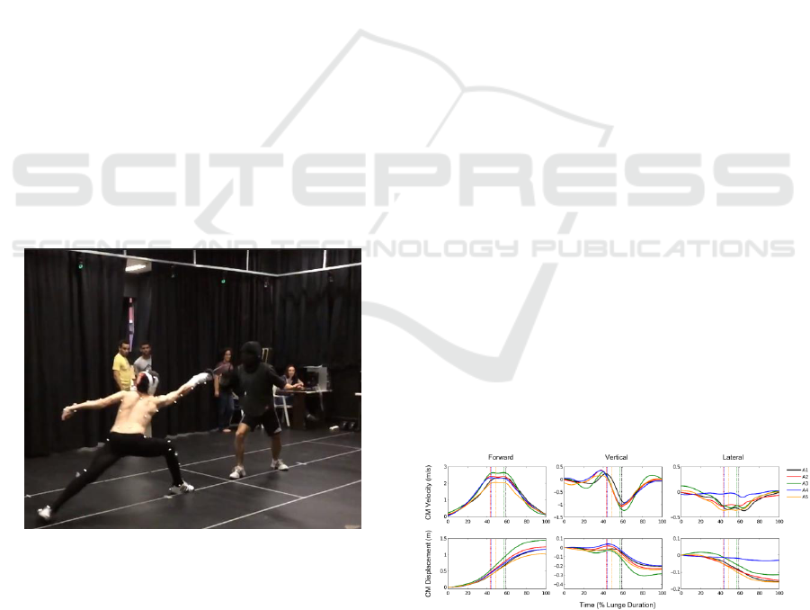
marker occlusion). (Figure 1).
Figure 1: Lunge motion captured using Optitrack system.
Data from the best-executed lunge attack of each
athlete in each condition, as judged by the coach,
was selected for inclusion in the digital platform.
Body pose during the lunge attack period was, thus,
exported, for animation purposes, using Biovision
Hierarchy format (bvh). In addition, the tri-
dimensional coordinate of each retroreflective
marker in the corresponding period, was exported in
c3d format, for kinematic analysis purposes. All the
relevant kinematic quantities calculation, as well as
the necessary data processing, were done with the
Visual 3D software (5.01 version, C-Motion). The
variables selected for analysis were based on the
criteria used by the coaches to judge the athlete
performance (Correa et al, 2015).
We used the Calibrated Anatomical System
Technique (CAST; Cappozzo, 1995) to calculate the
body segments instantaneous position and
orientation. The 3D joint rotations (joint angles)
were computed via Euler angles using the Cardan
sequence (flexion-extension, abduction-adduction,
axial rotation). Inertial characteristics of each body
segment were estimated according to the Zatsiorsky-
Seluyanov model modified by deLeva (deLeva,
1996).
The following variables were selected to analyse
the lunge: the foot angle relative to the anterior-
posterior direction (toe in-out angle); the angle
between the longitudinal axis of both feet; base
length and width; horizontal position of the centre of
mass (CM) relative to the unarmed (back) heel; each
segment, as well as whole body, CM displacement
and velocity in the forward, vertical and lateral
directions; the 3D angular displacements and
velocities of the upper and lower limb joints for
both, armed and unarmed, sides; pelvis and trunk
angular motion in the sagittal plane. The time series
of those variables were filtered using a 4th order,
zero leg, low-pass Butterworth filter, with a 6 Hz cut
off frequency. (Klauck and Hassan, 1998).
The digital platform allows the user to visualize
the time series and instantaneous values of
biomechanical variables, by selecting the
corresponding joint or segment at the movement
animation. At the present, the following variables
are allowed for visualization: ankle, knee, hip, wrist,
elbow and shoulder joint angle at the frontal
(abduction-adduction) and sagittal plane (flexion-
Figure 2: Whole body center of mass (CM) displacement
and velocity in the forward, vertical (upward positive) and
lateral (unarmed side, positive) directions, during a lunge
attack without the presence of any target to be hit, at the
best performance of each one of the five athletes analyzed.
Vertical lines indicate the instant at which CM achieved
the higher forward velocity.
icSPORTS 2016 - 4th International Congress on Sport Sciences Research and Technology Support
40
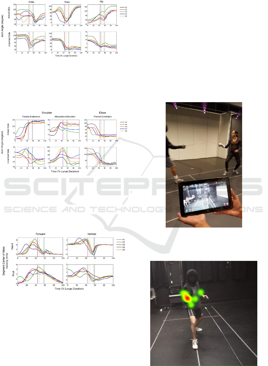
Figure 3: Joint angle in the sagittal plane for the armed
side and unarmed side lower limb joints, during a lunge
attack without the presence of any target to be hit, at the
best performance of each one of the five athletes analyzed.
An increase in joint angle means joint flexion. Vertical
lines indicate the instant at which the athlete’s CM
achieved the higher forward velocity.
Figure 4: Joint angle in the sagittal plane (shoulder and
elbow) and frontal plane (shoulder) for two of the armed
side and unarmed side upper arm joints, during a lunge
attack without the presence of any target to be hit, at the
best performance of each one of the five athletes analyzed.
An increase in joint angle means joint flexion and
abduction, respectively. Vertical lines indicate the instant
at which CM achieved the higher forward velocity.
Figure 5: Foot and Hand center of mass (CM) velocity in
the forward and vertical (upward positive) diraction,
during a lunge attack without the presence of any target to
be hit, at the best performance of each one of the five
athletes analyzed. Vertical lines indicate the instant at
which CM achieved the higher forward velocity.
extension), as well as the CM linear displacement
and velocity for the whole body, pelvis, trunk, head,
upper and lower arms, hands, feet, shanks and
thighs. An example of the data feeding the platform
can be seen in the figures. The data for the 5 athletes
(A1-A5) are shown together just for illustration
purposes. (Figure 1,2,3,4,5).
2.2 Visual Tracking Collection
The same fencing athletics were evaluated with
regard to their gaze behavior during their training
practices. For that, the athletes performed their
training section using an eyetracking (TobiiGlasses
2) under their protective masks. This device has 4
cameras to monitor the retinal movements and a
camera that records the images seen by the subject.
Data were analyzed with the TobiiGlassesAnalyzer
(version 1.16). (Figure 6).
Figure 6: Athletes using Eye tracking device.
Three main areas of interest (AOI) were identified in
the subject field of view, which were: the opponent's
Figure 7: Colour mapping that shows the areas of interest.
3D Interactive Environment Applied to Fencing Training
41
arm, trunk and face (mask). The frequency the
athletes focused on each AOI were calculated.
(Figure 7).
The results of these steps were inserted in the 3D
Digital Platform or 3D Interactive Environment.
3 PLATFORM DEVELOPMENT
The Virtual Platform was developed using mostly
“game technologies” since they are currently the
best available tools for virtual scenes 3D. The core
system was based in Unity3D (www.unity3D.com)
with addition of some add-ons such NGUI
(http://www.tasharen.com/) and others. The system
was split in modules to better organization of the
development and it components are presented in
Figure 8.
Figure 8: System Module Diagram.
Core System: Is the main framework where all
the systems are integrated. It includes menus, 3D
viewport, graphs, skeleton reconstructions and
other interfaces.
Animation System: Present the captured
animation using a skeleton reference where you
can select bones or joints.
Graph System: Synchronized with the
animations we present some graphs related to
the captured movements. This include Bone
Rotation, Position and others.
Eyetrack Database: Here, the Eye Track data
collected were made available.
The interface of the system was planned to be
easy to use and understand, an important feature
since mostly of the users may not have fluency in
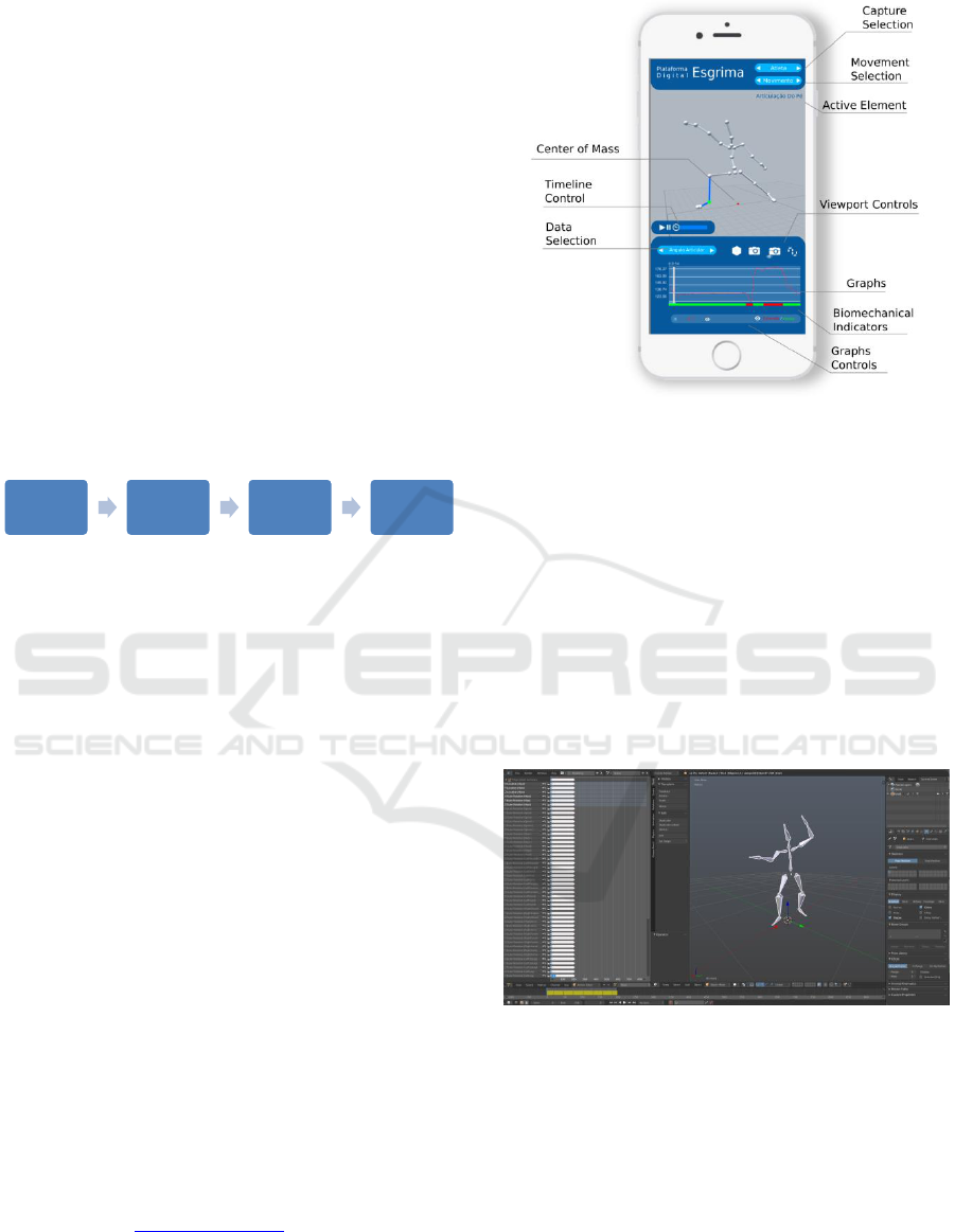
digital applications. In the Figure 9 you can see the
main interface of the Mobile version, the desktop
layout is yet in development.
During the development was implemented a
process to insert all the data in the platform, it
follows some tasks:
The model captured in BVH format is imported
in Blender (www.blender.org) (Figure 10)
It animations are converted to a metric scale of
0.001, that way the model gets 1:1 scale when
imported in Unity.
Figure 9: Main Interface of the mobile version.
All the animation poses are cleaned for wrong
keyframes and the correct segment that
represents the movement of interest.
All the segments (bones and joints) are renamed
for a correct standard that we can read in the
platform. It’s used to the skeleton
reconstruction.
All the data are imported and converted to a
XML file. That way we can read it in the
platform and plot the Graphs.
The model is exported as FBX format that can
be read by the platform
Figure 10: Clean-up and Name Fixes Process in Blender.
3.1 Graph System
The Graph System shows selected data from
elements of interest of the model. It can be a data of
a Segment, a Joint or not necessarily associated to a
skeleton element as a gravity center e.g. the figure 4
shows the Desktop version of the platform using the
Graph system. (Figure 11).
Core
System
Animation
System
Graph
System
EyeTrack
Database
icSPORTS 2016 - 4th International Congress on Sport Sciences Research and Technology Support
42
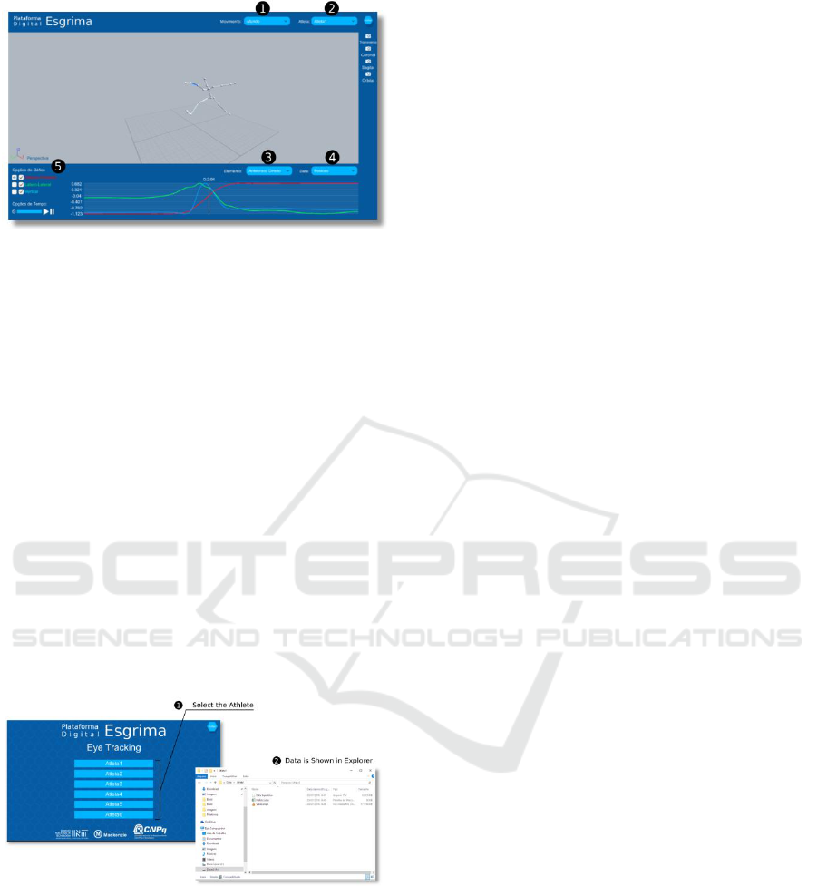
Figure 11: Desktop Platform with the Graph System.
1. To select the Movement to Analyze
2. To select the Athlete
3. To select the Element to Analyze
4. To select the Data to show the Graph
5. To select options as Axis and Scale to Show
3.2 EyeTrack Database
Inside the EyeTrack Database we can find all the
data collect from the eyetrack system of the athletes.
It commonly contains 3 files:
.tsv file with the RAW data of the Eyetrack
.xlsx file with a more accessible data that can
be read in Excel
.mp4 video with the Eyetrack mirroring what
the athlete sees during the execution of the
movement
The image above shows the usage of the
eyetrack database. (Figure 12).
Figure 12: Eye Tracking Usage.
4 CONCLUSIONS
The 3D digital platform is an attempt to approach
fencing coaches and researchers in order to explore
biomechanical factors and visual aspects that may
lead to an improvement on epee fencing technique,
as well as in teaching and training methods. Its
support to mobile and desktop highlights the
importance of visualization and interaction of the
coach with results on the biomechanical parameters
and visual search strategies in a more understandable
and relevant way to training.
Based on coach's criteria, it was identified the
importance of the upper body and center of mass
kinematic variables to lead to a good lunge
performance. Another aspect of the research is the
identification of what is the most relevant visual
information to predict the movement of the epee and
opponent.
ACKNOWLEDGEMENTS
Acknowledgment: CNPQ is the sponsor agency of
this research
REFERENCES
Capozzo, A., Catani, F., Della Croce, U., & Leardini, A.
1995. Position and orientation in space of bones
during movement: anatomical frame definition and
determination. Clinical Biomechanics, 10, 171.
Corrêa, S. C., Orselli, M. I. V. , Xavier, A. P., Salles, R. J.
D.,Cid, L.G., Guimaraes, C. P.2015 . Kinematics
fencing's analysis based on coach's criteria. In: 33
International Conference on Biomechanics in Sports,
2015, Poitiers. Annals of the 33 International
Conference in Biomechanics in Sports.
Correia, W. R., Franchini, E. 2010. Produção acadêmica
em lutas, artes marciais e esportes de combate (in
Portuguese). Motriz, 16, 1-9.
de Leva, P. 1996 Adjustments to Zatsiorsky-Seluyanov's
segment inertia parameters. Journal of Biomechanics.
Vol. 29 , nº 9, pp: 1223-30.
Guimaraes, C. P., Balbio, V., Cid, G. L. Zamberlan, M. C.
Pastura, F., Paixao, L. 2015. 3D virtual environment
system applied to aging study - Biomechanical and
anthropometric approach, Proccedia Manufacturing 3,
pp: 5551 – 5556.
Klauck, J, Hassan, S.E.A. 1998. Lower and upper
extremity coordination parameters during the fencing
lunge. In Proceeding of the 16th International
Symposium on Biomechanics in Sports.
Oliveira, R. F., Oudejans, R. R. D., Beek, P. J. 2008. Gaze
behavior in Basketball shooting: Further evidence for
online visual control, Research Quarterly for Exercise
and Sports, vol. 79, nº3, pp: 399-404.
Roi, G., Bianchedi, G. 2008. The Science of Fencing:
Implications for Performance and Injury Prevention.
Sports Medicine, 38, 465-81.
3D Interactive Environment Applied to Fencing Training
43
