
Functional Evaluation of the Solid Model Creation
using 3D Direct Drawing System
Kaoru Mitsuhashi
1
, Hiroshi Hashimoto
2
and Yasuhiro Ohyama
1
1
Department of Mechanical Engineering, School of Engineering, Tokyo University of Technology, Hachioji, Tokyo, Japan
2
Master Program of Innovation for Design and Engineering, Advanced Institute of Industrial Technology, Tokyo, Japan
Keywords: 3D Direct Drawing, ARToolKit, Solid Model, Projective Method, Taguchi Method.
Abstract: 3D model of computer is usually created using 3D CAD software, but 3D direct drawing method is still
developing the research. In this paper, we suggest and construct the 3D direct drawing system with ARToolKit
and develop the required creating methods and tools. The method is the creating solid algorithm using
projective methods. The algorithm is the converting multiple surfaces into a solid. After that, the functionality
of the methods and tools are evaluated using the Taguchi method (quality engineering). In addition, we
investigate the optimal condition of the creating methods and tools required for modeling.
1 INTRODUCTION
Recently, most of products have been designed via 3D
CAD models. In order to get a good appearance, the
products developed for the consumers have many
solid models. Then, the requirement for developing
solid models is increasing, and these solid models are
designed using 3D CAD software. 3D CAD software,
which are CATIA
TM
, SolidWorks
TM
, Rhinoceros
TM
,
etc., is used for creating 3D solid models. A mouse
and a keyboard are key components for using the
software. However, creating 3D solid models needs
special skill and training. Intuitive 3D modeling
based on conceptual design is very difficult.
On the other hand, 3D direct modeling methods
without using 3D CAD software have been proposed,
in order to carry out 3D modeling easily. According
to haptic devices, the space to draw is decided in
advance to give a kinesthetic sense (Keefe, Zeleznik,
Laidlaw, 2007), or an existing model is deformed by
cutting and modifications (Chen, Yan, Lian, 2005),
(Akgunduz, Yu, 2004). However, the 3D model
cannot be created intuitively. In addition, it takes a
long time to form as a conceptual model. In contrast,
3D direct drawing researches have also been done.
They involve drawing/creating using a sensor
(Wesche, Seidel, 2001), (Bruno, Luchi, Muzzupappa,
2002) or camera (Cheok, Chuen, Eng, 2002).
However, they are not efficient system, because their
equipment is complicated and needs a large space.
The conceptual design modeling is difficult without
haptic sense. Therefore, they are neither popular nor
innovative.
In previous papers, the algorithm to create a
polygonal model and a curved surface model is
suggested and investigated (Mitsuhashi, Yoshida,
etc.…, 2014). However, we have never researched the
3D solid model, because creating method of solid
model is various. The conventional method is B-Reps
(Boundary representation) method or CGS
(Constructive Solid Geometry) method (Llamas,
Kim, etc.…, 2003). They make the 3D model rapidly,
but are difficult to operate only visual sensation and
too many commands.
In this paper, we construct the method for creating
a solid model in a 3D direct drawing system, so as to
create a 3D solid model easily. Then, the algorithm to
create a solid model is suggested. The algorithm is a
projective method, which is used as a third angle
projective method in mechanical design. Some
conventional methods used for surface drawing are
employed in 3D drawing, and the functionality of
these methods is evaluated by the Taguchi method
(quality engineering) to search for the most effective
method (Roy, 1990), (Yokoyama, 1988). In
particular, the function of creating methods or tools in
3D direct drawing is evaluated, and the optimal
method for drawing curved surfaces is proposed.
Mitsuhashi, K., Hashimoto, H. and Ohyama, Y.
Functional Evaluation of the Solid Model Creation using 3D Direct Drawing System.
DOI: 10.5220/0006007005130521
In Proceedings of the 13th International Conference on Informatics in Control, Automation and Robotics (ICINCO 2016) - Volume 2, pages 513-521
ISBN: 978-989-758-198-4
Copyright
c
2016 by SCITEPRESS – Science and Technology Publications, Lda. All rights reserved
513
2 3D DIRECT DRAWING
SYSTEM WITH ARTOOLKIT
Many kinds of 3D direct drawing systems exist, but
no popular drawing system exists, because they are
expensive, difficult to operate, and require a large
space. In contrast, 3D drawing using AR (Augmented
Reality) with markers can be used to display 3D
models easily. Therefore, we use ARToolKit in the
3D drawing system. ARToolKit is a programming
library for C/C++ language to support AR
implementation. It is an open source, and the source
code is available easily. It has many functions, such
as the recognition of marker detection and patterns,
measurement of the position and posture of the
marker, and composition display of the photographic
image and the 3D CG model.
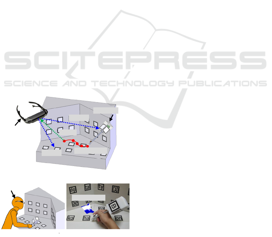
Figure 1 shows the schematic and the photograph
of the 3D drawing system with ARToolKit. An
operator carries the pen-type marker for carrying out
commands in the arranged marker for determining
space, equipping a Head Mount Display (HMD), and
controlling a web camera. The web camera measures
the distance between a marker for command and
space, and reads the contents of the marker command.
It has a resolution of 640×840 pixels. After measuring
the distance and reading the command, points, lines,
and surfaces (only when lines are created) can be
output from the pen’s nib and displayed by the HMD
in the drawing space. Display of objects, such as
points, lines, and surfaces, is carried out via the
Figure 1: 3D direct drawing system with ARToolKit.
OpenGL library. Two light sources are set above the
drawing space. The objective color can be selected
from red, green, and blue. It should be noted that
points or lines are always output only by indication of
the marker. However, the operator cannot have yet
drawn concept shapes using only virtual reality and
graphic software. Then, the button switch having an
ON/OFF function is equipped on the fingertip of the
pen. This function enables the operator to control the
output of points or lines. Furthermore, the operator
moves unexpectedly in many cases, which causes the
arm, head, or body of the operator to swing. For this
reason, a drawing speed of 1.0 - 10.0 mm/s is adopted.
Thus, the creation of unexpected points or lines can
be prevented. The contents of the AR command
markers determine of the color of the object, the
output of a point or line, creation of a surface, and
movement or elimination of a point or line. Space
markers are set at the bottom of the wall in drawing
space. The area of the large marker is 50mm×50mm,
whereas that of the small marker is 20mm×20 mm.
After the web camera has detected the position and
direction of space markers and command markers,
the drawing object is displayed from the fixed space
markers.
3 METHOD AND TOOL FOR
CREATING SOLID
Many kinds of 3D drawing methods exist, but none
of them is effective. Then, we constructed and
investigated the methods and tools with ARToolKit.
We explain an example of these methods in the
following sections.
3.1 Command Marker Pen
For drawing points, lines, and surfaces in the drawing
space, it is necessary to use the 3D direct drawing
tools. In this paper, we use the AR marker in a manner
similar to that in a previous study. AR markers enable
operators to give more commands than a point
marker. Furthermore, we can control the drawing
time by the use of an ON/OFF draw switch equipped
on the fingertip. It is difficult to say which type of AR
marker pen is the most effective because of their
various applications. Hence, we developed three
kinds of the command marker pen in this study in
Figure 2. The first is the large marker pen (in Figure
2(a)). It is generally called the AR marker rod in
ARToolKit. The second is a small marker that has
reduced weight and that divides the command
Marker pen
HMD with
web camera
Marker space
Measure
Display
Line with trace
(a) Scheme
(b) Situation from outer
Operator
(c) Situation from HMD
Measure
Drawing object
ICINCO 2016 - 13th International Conference on Informatics in Control, Automation and Robotics
514
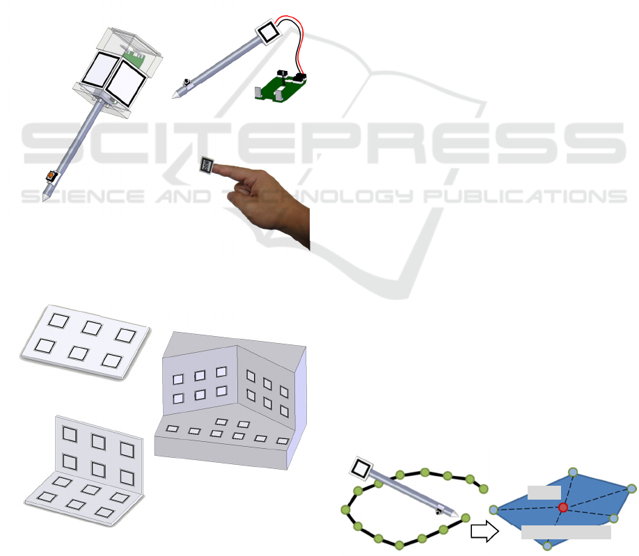
function and the drawing output (in Figure 2(b))
(Cheok, Chuen, Eng, 2002). The third is a small
marker equipped on the fingertip similar to the one
used in a previous study (in Figure 2(c)). We
investigate which pen is useful.
3.2 Drawing Space
When 3D direct drawing is performed with
ARToolKit, it is necessary to prepare the fixed
marker space. Generally, it is said that a good result
is obtained as many established markers are set in the
entire drawing space. However, the computational
complexity is enormous, and it is difficult to set the
space because of the presence of obstacles. Then, we
prepared three kinds of drawing spaces, which are
shown in Figure 3. The first is a plane drawing space
(only XY plane), similar to the one used in a previous
Figure 3: Drawing space.
study (in Figure 3(a)) (Cheok, Chuen, Eng, 2002).
The second space consists of two right-angled planes
(XY plane and XZ plane) so as to observe the top and
bottom direction (in Figure 3(b)). The third space
consists of three planes where the XZ plane is bent to
form an angle of 120 degrees in order to widen the
angle of the space (Figure 3(c)). We investigate which
drawing space is useful.
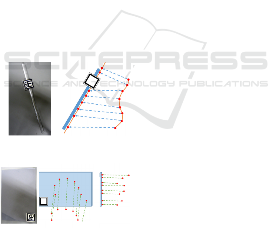
3.3 Polygonal Surface Drawing
We should create the some polygonal surfaces to
create a solid model. The creating method of
polygonal surface is shown in Figure 4. First, line
segments (or point clouds) are drawn by detecting the
position of one hand using Kinect. Then, all the
drawing points are projected to the one plane using
the Least squares methods. Second, the center point
is calculated from all the points, and the most distant
point is elected from the center point (Mitsuhashi,
Yoshida, etc.…, 2014). It is a 1st vertex of polygonal
surface. In a square, the segment between the center
and 1st vertex is rotated 90 degree counterclockwise
towards the normal vector of the one plane. In a
triangle, the angle is 120 degrees. In a n-polygonal,
the angle is 360/n degree. Polygonal surface is created
by connecting among the neighbor vertexes.
3.4 Design Support Tool
PC software can create a straight line or rectangular
or square, but freehand drawing in 3D space is
difficult for them. Then, we suggest the design
support tools. Figure 5 shows the straight edge ruler,
Figure 6 shows the absorption plane ruler. Both rulers
are made of acrylic material with AR marker, because
acrylic material prevents the rulers from disappearing
drawing space markers. The straight edge ruler in
Figure 5 can draw the straight line or segment,
because the drawing points are absorbed on the ruler.
The absorption plane ruler can draw the segment or
face on one plane, it has the same function. It is a
necessary tool, because a plane drawing in 3D space
is difficult. Therefore, we can create the segment and
the face (polygonal surface, circle, etc.…) easily.
Figure 4: Drawing method of Polygonal surface.
AR marker
AR marker
Switch
Switch
AR marker
(a) Large marker type
(b) Small marker type
(c) Fingertip type
Figure 2: Drawing pen.
(a) One plane
(b) Two planes (right-angled)
(c) Three planes
(wide-angled)
AR marker
AR marker pen
Center
Polygonal surface
Convert
Functional Evaluation of the Solid Model Creation using 3D Direct Drawing System
515
Then, we investigate the effects of design support
tools.
4 SUGGESTIONS OF
ALGORITHM FOR CREATING
SOLID
4.1 Solid Creating Method
Drawing a point, segment, and surface in gesture is
easy, but solid is difficult. Because human
recognition and image 2D objects, can’t image 3D
objects in detail. The conventional 3D modeling
method is B-Reps (Boundary representation) method
or CGS (Constructive Solid Geometry) method
(Akgunduz, Yu, 2004), (Llamas, Kim, etc.…, 2003).
B-Reps method transforms many closed points to
segment, many closed segments to surface, many
closed surfaces to solid. It has the information about
the position and vector of vertex, edge, and face. It is
easy to create a complicated shape, but it must close
all the face. Therefore, we must draw many surfaces
with great difficulty. We are pained to draw and close
many surfaces and can’t create the solid well in
Figure 6: Absorption plane ruler for 3D space.
previous papers (Mitsuhashi, 2012). On the other
hand, CSG method gives the primitive objects that are
cuboid (cube), cylinder, cone, pyramid, and spheroid
(sphere). And the primitive objects are assembled into
the complicated shape using Boolean operations.
CSG method has the information about the primitive
shape, position, size, combination. The information
has simple tree structure. So we can use the function
Redo or Undo easily. However, the complicated
shape takes many Boolean operations, that is difficult,
painful, and not intuitive. Because we create or draw
lots of the 2D models in 3D modeling. In addition,
CSG method can’t deform the solid model intuitively.
So we suggest an algorithm to create solid model
using the projective method. It is already introduced
at MasterCAM
TM
, Solidworks
TM
. When two or more
of polygon surface are created, they can be converted
to a solid. However, it has never used in 3D real
space. So we suggest an algorithm to create solid
model using the projective method in 3D real space.
4.2 Solid Creating Projective Method
in 3D Real Space
We construct the program using the projective
method in 3D real space, in order to create solid
model. Figure 7 shows the schematic diagram of a
projective method in 3D real space. Solid model is
projected and created from front, side, and top surface
in Figure 7. Thin lines are prism edges. The scheme
is that two or more of polygonal surfaces are drawn at
first, after that they are converted as a section of prism,
and an infinitely long prism is created. Then, the
scheme (program) finds the intersection of all prisms,
it calculates the boolean logical product (AND
operation), and the intersect solid model is created.
These algorithms are calculated by OpenCSG and
OpenSCAD library. Creating solid data is converted
to STL (Stereo Lithography) file or OFF (Object File
Format) file.
Figure 8 shows the solid made by the projective
method in 3D real space. When a polygonal surface
is created, prism edges are the role of the guide from
Figure 8. The solid is displayed by many polygonal
surfaces using OpenGL and ARToolKit. The operator
can decide the position of solid with watching the
guide.
(a) All over view
(b) Scheme
Absorb
Real drawing trajectory
Output line
Figure 5: Straight edge ruler for 3D space.
Absorption to plane
Real drawing trajectory
Absorption
to plane
Real drawing
trajectory
(a) All over view
(b) Scheme
ICINCO 2016 - 13th International Conference on Informatics in Control, Automation and Robotics
516
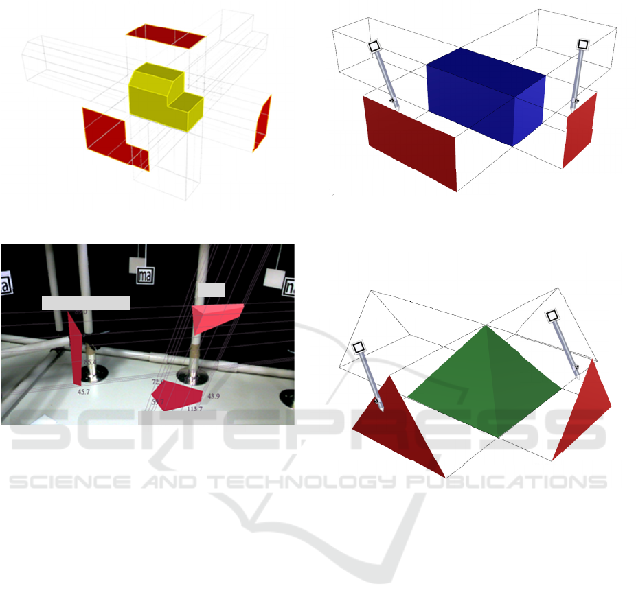
Figure 8: Situation of projection method.
4.3 Creating Algorithm for
Cube/Cuboid and Pyramid
The algorithm of creating a solid is to convert
multiple polygon surfaces using the projective
method from the preceding section. Figure 9 shows
the creating algorithm for cube or cuboid. The
operator can use single hand or double hands or both,
in creating a polygonal surface using Kinect, but can’t
create multiple surfaces at the same time. If two or
more of rectangular surface is drawn, a cube/cuboid
is created. Therefore, the operator can create the solid
like gesture experiment results. Figure 10 shows the
creating algorithm for a quadrangular pyramid. If two
or more of triangle surface is drawn, a quadrangular
is created. Then, triangular pyramid is the same
algorithm. On the other hand, the same algorithm
enables to create a sphere or spheroid theoretically,
but the operator must create the infinite circle or
curved surface. A polyhedron like sphere/spheroid
can be created, it is not sphere/spheroid. So the
creating algorithm for sphere/spheroid is in future
work.
Figure 10: Creating algorithm of pyramid.
5 FUNCTIONAL EVALUATION
OF 3D DRAWING USING THE
TAGUCHI METHOD
There is extremely little research on the evaluation of
the functionality of 3D direct drawing methods and
tools. Evaluating the constructed methods and tools
requires a large number of experiments. We
investigate the functional evaluation of the drawing
methods and tools via experiments using Taguchi’s
L18 orthogonal array in this paper (Roy, 1990),
(Yokoyama, 1988).
Solid
Prism
Prism
Prism
Polygonal surface
Polygonal surface
Polygonal
surface
Figure 7: Solid creature projection method in 3D space.
Polygonal surface
Polygonal surface
Solid
1. Draw surface
1. Draw surface
2. Make prism
(infinite depth/height)
2. Make prism
(infinite depth/height)
3. Solid creation
Figure 9: Creating algorithm of cuboid/cube.
1. Draw surface 1. Draw surface
2. Make prism
(infinite depth/height)
2. Make prism
(infinite depth/height)
3. Solid creation
Functional Evaluation of the Solid Model Creation using 3D Direct Drawing System
517
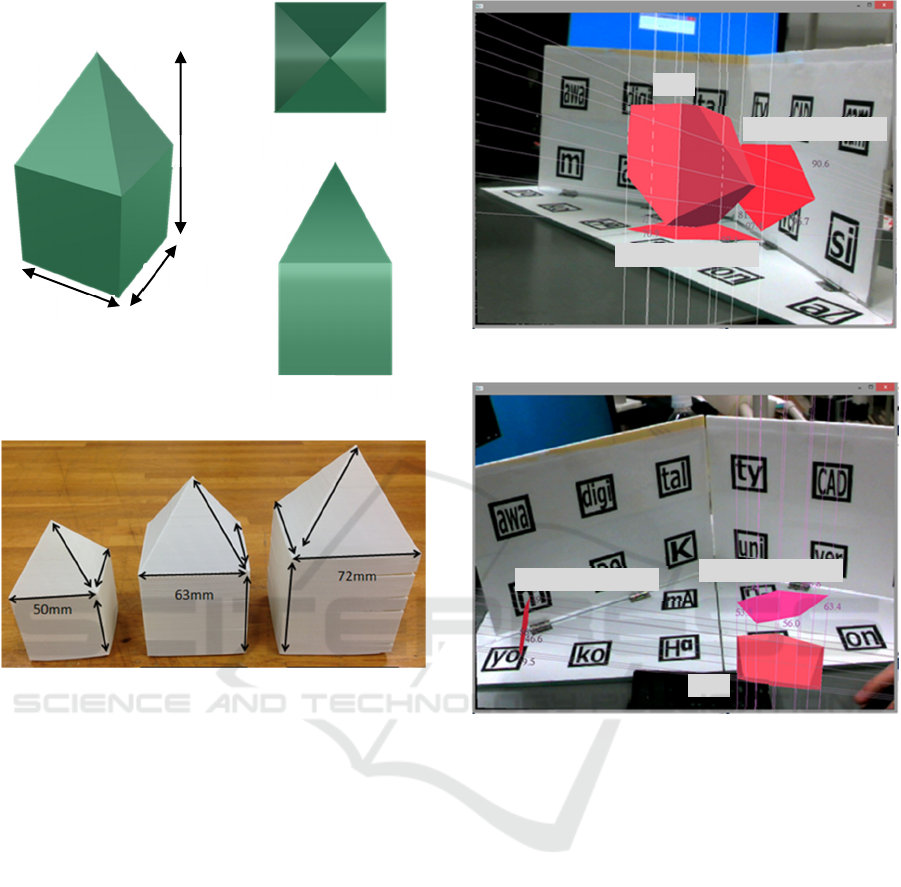
Figure 12: Change the volume sample model.
5.1 Experiment
We evaluate the shape of the solid model. The use of
any of the three methods should yield the required
model. We adopted a combination solid model of the
pyramid and the cube, which is usual to create with
3D-CAD software. Because a large number of models
must be evaluated, as stable solid models cannot be
drawn repeatedly, it is difficult to evaluate shape error
by using static characteristics. Thus, we adopt
dynamic characteristics, not static characteristics.
Figure 11 (a) shows an example of the solid model.
The bounding box is 50mm wide, 50mm deep and
93mm high. The change in the edge of the solid model
in the bounding box is considered as the signal factor.
The volume is output when the edge is changed.
Figure 12 shows the shape when the edge is changed.
The relations of the edge M' and the volume y' are (a)
M'
1
=50mm, y'
1
=160833mm
3
, (b) M'
2
=63mm,
y'
2
=321667mm
3
, and (c) M'
3
=72mm,
y'
3
=482500mm
3
. Then, we calculate the proportional
Figure 13: Creating solid model.
reference point expression based on 50mm height.
Proportion relations of y=βM
3
are obtained as results.
The operator traces the preparation guide of the solid
model. Figure 13 shows an example of the creating
process.
5.2 Determination of Control and Noise
Factors in the L18 Orthogonal
Array Experiment
Seven control factors of the three levels and one
control factor of two levels are set, for the experiment,
to evaluate the functionality of the drawing methods
and tools. The control factors are type of input
method for the drawing tool, type of drawing space,
and support tool. The other factors are the edit
function of the drawing point, the guide character, the
3D display function, the change section size of the
pyramid, and the number of the necessary faces
(a) Default (b) Two times (c) Three times
(a) Perspective
(c) Front view
(b) Top view
Height
Depth
Width
Figure 11: Sample model (cube + pyramid).
Polygonal surface
Polygonal surface
Solid
(a) Using the rulers
(b) Useless the rulers
Polygonal surface
Polygonal surface
Solid
ICINCO 2016 - 13th International Conference on Informatics in Control, Automation and Robotics
518
(surfaces) for projective method. The edit methods
involve the removing or moving function, which
changes a polygonal surface shape. The display
function of the guide character is CG model, real
model, and nothing. The number of necessary faces
in the solid model is 2 or 3. The noise factor indicates
the change in the shape caused by the operator, and
its effect was examined with the help of two 30-years-
old men (noise factor: N
1
, N
2
). Tables 1-3 list the
control factors, the results of the L18 orthogonal array
experiment, and the relation of the output to the signal
factor and the noise factors, respectively. Here, the
third level of the control factor E and F are assumed
as a dummy level because this factor has only two
parameters.
5.3 SN Ratio
After an experiment is carried out, we must evaluate
the SN (signal-to-noise) ratio
η
. The SN ratio
η
is an
index for expressing the stability of the noise level.
Therefore, SN ratio η were calculated in this study.
The expressions of
η
[dB] are as follows.
=
−
=
3
1
2
2
log10
i
iN
e
MV
VS
β
η
(1)
Here, S
β
is the promotional variation, S
e
is the
error variation, V
e
is the error variance, and V
N
is the
noise variance. The expressions are as follows.
=
==
=
3
1
2
2
2
1
3
1
,
2
i
i
ji
jii
M
yM
S
β
(2)
()
41132
2
1
3
1
2
,
β
Sy
S
V
ji
ji
e
e
−
=
−−×
=
==
(3)
()
()
132
3
1
2,1,
−×
+−
=
=
e
i
iii
N
SyyM
V
(4)
Then, the optimum control factor is decided by
η
, wh
ich is remarkably high.
Table 1: Control factors (*: Current condition).
Table 2: L18 orthogonal array experiment.
Table 3: Relation of outputs to signal factors
and noise factors.
5.4 Results and Repeatability
Table 4 shows the averages of SN ration according to
the level of all the control factors. Figure. 14 shows
the graphs of their factorial effects. We selected the
optimum levels where the SN ratio is remarkably
high. In other words, we give priority to the difference
in the SN ratio only when a change in the SN ratio
made a slight difference. Therefore, it was found that
the factors affecting the SN ratio are the number of
faces, the drawing space, the display of guide model,
and the editing function. If there are too less faces, a
No. A B C D E F G H
1 11111111
2 11222222
3 11332'2'33
4 12112233
5 12222'2'11
6 12331122
7 131212'23
8 13232131
9 13312'212
1021132'221
11212112'32
1221322113
1322122'132
1422231213
15223122'21
16231322'12
1723212'123
1823321231
M
1
M
2
M
3
N
1
y
11
y
21
y
31
N
2
y
12
y
22
y
32
1st level 2nd level 3rd level
A: Face 2 pieces* 3 pieces -
B: Pen type Large Small Fingertip*
C: Space 1 plane* 2 planes 3 planes
D: Edit Translate Erase Nothing*
E: Edge ruler With Without* -
F: Plane ruler With Without* -
G: Guide Display Real CG Notihing*
H: Section size 1 time* 2 times 3 times
Functional Evaluation of the Solid Model Creation using 3D Direct Drawing System
519
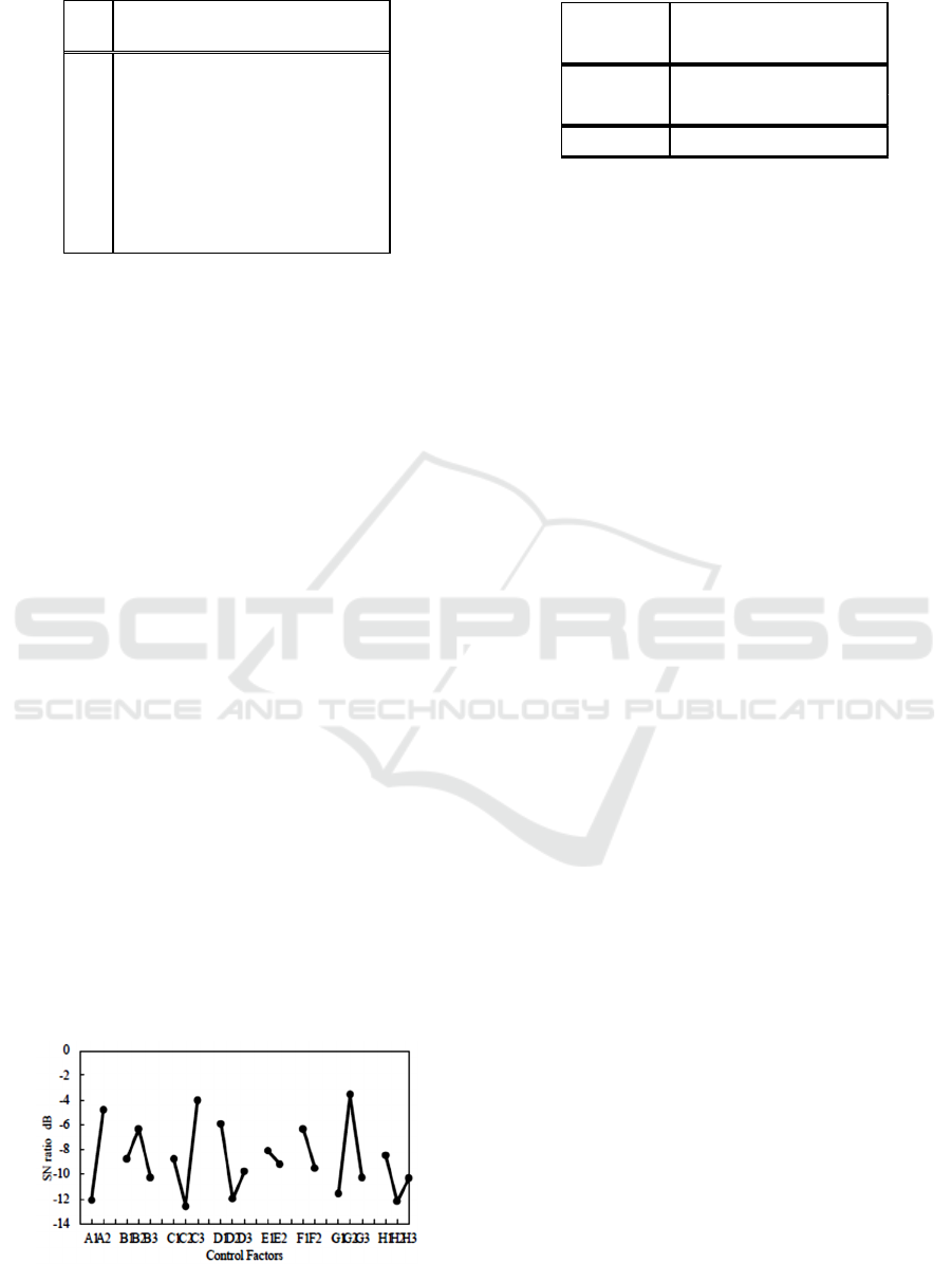
Table 4: Average of SN ratio at all control factors level.
shape can be wrinkled and be different from the
conceptual shape; however, the change in the shape
decreases if there are too many faces. With respect to
the guide model displayed, it is difficult to determine
a position if the guide model cannot display. With
respect to the editing function, the SN ratio of the
point translate function is the best, because it is
believed that the unintentional removal point occurs.
In terms of the drawing space, the SN ratio of the 120
°wide model is the best, because the range of vision
is spread out. Determining the optimum method for
drawing a solid model becomes the future problem.
Other factors have little influence on the modeling.
Therefore, the optimum condition for drawing solid
models is assumed as A
2
B
2
C
3
D
1
E
1
F
1
G
2
H
1
.
It is necessary to check the repeatability of this
optimum condition, in addition to determining the
current condition. The condition is assumed as
A
1
B
3
C
1
D
3
E
2
F
2
G
3
H
1
from conventional research.
Experiments under the two conditions were carried
out for validation. Table 5 lists the results of the
confirmation experiment and the estimation of the SN
ratio. Here, the estimation is carried out using the
averages, according to the level of all control factors.
From the results, it was found that the optimum
condition showed a higher SN ratio than the current
condition. Therefore, the repeatability of this
optimum condition was confirmed. However, further
research on the few kinds of drawing tool proposed,
re-investigation of the method for the drawing
another solid model.
Figure 14: SN ratio of factorial effects.
Table 5: Confirmation experiments.
6 CONCLUSIONS
In this paper, we construct the method for creating a
solid model in a 3D direct drawing system, so as to
create a 3D solid model easily. Then, the algorithm to
create a solid model is suggested. The algorithm is a
projective method. After that, the functionality of the
methods, tools, and factors in 3D drawing is
evaluated using the Taguchi method (quality
engineering). In this result, we find that the effective
control factors are the number of faces, the drawing
space, the display of guide model, and the editing
function. Furthermore, in order to investigate the
repeatability of this optimum condition, the
supporting experiment was performed for
verification. Further work can be focused on the kinds
of drawing tool proposed, re-investigation of the
method of drawing another solid model.
ACKNOWLEDGEMENTS
This work was in part supported by JST RISTEX
Service Science, Solutions and Foundation Integrated
Research Program.
REFERENCES
Daniel F. Keefe, Robert C. Zeleznik, and David H. Laidlaw,
Drawing on Air: Input Techniques for Controlled 3D
Line Illustration, IEEE Transactions on Visualization
and Computer Graphics, Vol. 13, No. 5, 2007
Yonghua Chen, Zhengyi Yang, and Lili Lian, On the
Development of a Haptic System for Rapid Product
Development, Computer-Aided Design, Vol.37, No.5,
pp. 559-569, 2005
Ali Akgunduz and Hang Yu, Two-Step 3-Dimensional
Sketching Tool for New Product Development,
Proceedings of the 2004 Winter Simulation Conference,
pp.1728-1733, 2004
Gerold Wesche, and Hans-Peter Seidel, FreeDrawer – A
Free-Form Sketching System on the Responsive
Workbench, VRST’01, November, pp. 15-17, 2001
123
A -12.11 -4.78
B -8.75 -6.34 -10.25
C -8.75 -12.59 -4.00
D -5.93 -11.97 -9.77
E -8.09 -9.16 -9.16
F -9.50 -6.34 -6.34
G -11.57 -3.52 -10.25
H -8.45 -12.20 -10.30
SN ratio [dB]
Estimate Confirm
Current -1.96 -7.29
Optimum -0.24 -0.70
Gain 1.72 6.60
SN ratio [dB]
ICINCO 2016 - 13th International Conference on Informatics in Control, Automation and Robotics
520

F. Bruno, M. L. Luchi, M. Muzzupappa, and S. Rizzuti, A
Virtual Reality Desktop ConFigureuration for Freeform
Surface Sketching, In Proceedings of XIV Congreso
Internacional de Ingeniería Gráfica, ed. F. F. Salazar
and A. A. Badiola de Miguel, Santander, Spain, 2002
Adrian David Cheok, Neo Weng Chuen Edmund, and Ang
Wee Eng, Inexpensive Non-Sensor Based Augmented
Reality Modeling of Curves and Surfaces in Physical
Space, Proceedings of the International Symposium on
Mixed and Augmented Reality (ISMAR
’
02) ISMAR
2002, 2002
Ranjit Roy, A Primer on the Taguchi Method, Society of
Manufacturing Engineers, 1990
Y. Yokoyama, Quality Engineering Lecture 4:
Experimental Design for Quality Designs, Japanese
Standards Association, 1988
Kaoru MITSUHASHI, Functional Evaluation of the
Curved Surface Created by 3D Direct Drawing, The
2nd IFToMM (International Federation for the
Promotion of Mechanism and Machine Science) Asian
Conference on Mechanism and Machine Science 2012,
November7-10,Tokyo,Japan, 2012.
Kaoru MITSUHASHI, Ikuo YOSHIDA, Jin-Hua SHE,
Yasuhiro OHYAMA, “Suggestion of 3D Direct
Drawing Method by Microsoft Kinect”, 15th
International Conference on Precision Engineering
(ICPE2014), July23-25, Kanazawa, Japan, 2014
Ignacio Llamas, ByungMoon Kim, Joshua Gargus, Jarek
Rossignac, and Christopher D. Shaw: Twister: a space-
warp operator for the two-handed editing of 3D shapes.
ACM Trans. Graph. 22(3), 2003, pp.663-668
Functional Evaluation of the Solid Model Creation using 3D Direct Drawing System
521
