
Model-based Recovery Connectors for Self-adaptation
and Self-healing
Emad Albassam, Hassan Gomaa and Daniel Menascé
Department of Computer Science, George Mason University, Fairfax, Virginia, U.S.A.
Keywords: Self-adaptation, Self-configuration, Self-healing, Dynamic Software Adaptation, Autonomic Computing,
Component Recovery, Recovery Patterns, MAPE-K Loop Model, Recovery Connectors, State Machines.
Abstract: Self-healing and self-configuration are highly desirable properties in software systems so that components
can dynamically adapt to changing environments and recover from failure with minimal human intervention.
This paper discusses a model-based approach for self-healing and self-configuration using recovery
connectors. A recovery connector extends connectors in component-based software architectures and service-
oriented architectures with self-healing and self-configuration capabilities so that a component or service can
be dynamically adapted and recovered from failures. The design of the recovery connector is based on the
MAPE-K loop model and can handle both recovery and adaptation.
1 INTRODUCTION
Connectors in component-based software
architectures (CBSA) are objects that interconnect
components and encapsulate a communication
protocol (Gomaa, 2011). Connectors encapsulate
frequently used communication patterns such as
asynchronous communication and synchronous
communication with reply. Previous papers
investigated adaptation connectors which are used to
adapt service-oriented software systems after original
deployment (Gomaa et al., 2010).
This paper investigates how a model-based
recovery connector integrates self-healing and self-
configuration capabilities. Recovery connectors are
used to separate adaptation and recovery concerns
from service concerns so that a service can be
transparently adapted and recovered from failures.
Recovery connectors are described for
architectural communication patterns that are
frequently used in service-oriented architectures
(SOA). The main architectural pattern in a SOA is the
client/coordinator/service pattern in which a
coordinator is an intermediary between clients and
service, with the goal of allowing services to be
autonomous and relatively independent of each other.
Within this overarching pattern, several other
communication patterns are used including
synchronous communication with reply,
asynchronous communication with callback, and
various brokering patterns including service
registration, and brokered communication.
Software adaptation involves dynamically
replacing, adding, or removing service, coordinator,
or client components at run-time in service-oriented
applications. Software recovery involves
dynamically replacing service, coordinator, or client
components after a run-time failure.
The contributions of this paper are the design and
validation of recovery connectors that dynamically
adapt and recover stateless and stateful services,
when client requests are idempotent, for different
architectural communication patterns in service-
oriented architectures.
The paper is organized as follows: Section 2
highlights key concepts and assumptions. Section 3
discusses the design of recovery connectors. Section
4 describes how recovery connectors can be used in
different SOA patterns. Section 5 contains validation
results. Section 6 discusses related work. Section 7
concludes the paper and discusses future work.
2 KEY CONCEPTS
This section describes the key concepts for providing a
systematic and reusable approach for self-healing and
self-configuration of CBSAs (Taylor et al., 2009).
Albassam, E., Gomaa, H. and Menascé, D.
Model-based Recovery Connectors for Self-adaptation and Self-healing.
DOI: 10.5220/0006005900790090
In Proceedings of the 11th International Joint Conference on Software Technologies (ICSOFT 2016) - Volume 1: ICSOFT-EA, pages 79-90
ISBN: 978-989-758-194-6
Copyright
c
2016 by SCITEPRESS – Science and Technology Publications, Lda. All rights reserved
79

Autonomic Control. Manual management of large
and complex software systems is difficult and costly.
Consequently, such systems should have the
following autonomic properties: self-healing, self-
configuration, self-optimization, and self-protection
(Kephart and Chess, 2003). The MAPE-K loop model
is widely used to implement autonomic controllers
and consists of four activities (monitoring, analysis,
planning, and execution) that operate on a
knowledge-base of the system. We use the general
MAPE-K loop model to support self-healing and self-
configuration of autonomic services.
Recovery Connectors. Recovery connectors are
used to separate adaptation and recovery concerns
from service concerns so that a service can be
transparently adapted and recovered from failures.
Recovery Patterns. A recovery pattern defines how
components in an architectural pattern can be
dynamically relocated and recovered to a consistent
state after a component has failed.
Message-Based Transactions. A transaction in
CBSAs is defined by Kramer and Magee as an
information exchange between multiple components
through messages (Kramer and Magee, 1990) while a
transaction in transactional processing systems is
defined as an atomic unit of work (Bernstein and
Newcomer, 2009). We combine these two definitions
as: a transaction is an information exchange between
two or more components through messages such that
either all messages in a transaction are eventually
exchanged or none of them are.
We make the following assumptions here:
• Only one component can fail permanently at a
time based on the fail-stop failure model
(Avizienis et al., 2004) in which components do
not send any erroneous messages but simply
cease functioning when they fail. Furthermore,
we assume that failures are not caused by
malicious attacks.
• Message delivery uses a reliable network
transport protocol.
• Recovery connectors do not fail.
• Clocks are synchronized between all nodes.
• Services can be either stateless of stateful with
idempotent operations.
3 RECOVERY CONNECTORS
This section describes the design of the basic
structure of a recovery connector for service-oriented
architectures. We assume that there are multiple
clients and a single service that processes multiple
client requests concurrently. The service responds to
each request from the client. The next section shows
how the same recovery connector design can handle
adaptation and recovery in other, more complex
architectural patterns.
The recovery connector manages transactions
between a client and a service that comprise either
single request/response messages or a dialog.
3.1 Design of the Recovery Connector
The service recovery connector (fig. 1) behaves as a
proxy for the service by receiving requests from
clients and then forwarding these requests to the
service. The recovery connector also receives
responses from the service, which are then forwarded
to requesting clients.
To ensure safe adaptation at run-time and
recoverability of service failures, the service recovery
connector must keep track of the transactions that the
service is currently engaged in and must maintain
messages (i.e. requests and responses) that pass
through it, so that these messages can be held during
adaptation and can be recovered in case the service
fails.
The service recovery connector has a control
object (Connector Control in fig. 1) that handles
sending messages to and receiving responses from
application components, and also handles adaptation
and recovery concerns of the service. To facilitate
maintenance of application messages, requests and
responses are stored by the connector in queues
located at the Service Request Manager and the
Service Response Manager (fig. 1), respectively.
Each manager is provided with a coordinator
component for controlling the queues it manages. The
goal of these coordinators is to separate the concerns
of queue management from adaptation and recovery
concerns handled by Connector Control.
3.2 Service Request Manager
Every request sent by a client to the service passes
through the Service Request Coordinator (fig 1). The
Service Request Coordinator maintains three queues
for storing client requests based on the status of these
requests, as follows:
Service Pending Queue (SPQ). The SPQ stores
requests received by the recovery connector from
clients but that have not yet been forwarded to the
service. The purpose of this queue is to buffer
requests for the service so that any requests received
by the connector while the service is being
ICSOFT-EA 2016 - 11th International Conference on Software Engineering and Applications
80

<<connector>>
:Service Recovery Connector
<<control>>
:Service Response Manager
<<control>>
:Service Request Manager
:Response Recovery Queue
(RRQ)
:Response Forwarding Queue
(RFQ)
:Service Pending Queue
(SPQ)
Request
ACK
Response
Forward Response
Response
<<service>>
:Service
<<coordinator>>
:Coordinator
<<client>>
:Client
Queue Request
Dequeue Request
Queue Request
Dequeue Request
Queue Response
Dequeue Response
Forward Request
Forward Response
Transaction Completed
Forward Response
Transaction Completed
Queue Response
Remove Transaction Responses
<<coordinator>>
:Service Request
Coordinator
<<coordinator>>
:Service Response
Coordinator
:Service Recovery Queue
(SRQ)
Queue Request
Remove Transaction Requests
:Service Active Queue
(SAQ)
:Active Transactions
Count
Increment
Decrement
<<state-dependent-
control>>
:Connector Control
Figure 1: Design of service recovery connector showing messages during normal execution.
dynamically adapted or is in the failed state are held
in this queue until the service becomes active again.
Thus, the SPQ ensures that no requests to the service
are lost due to dynamic adaptation or recovery.
Service Active Queue (SAQ). This queue stores
client requests that have been forwarded to the service
but do not have corresponding service responses at
the recovery connector, either because the service is
still processing the request and has not generated the
corresponding response yet or because the service
response was lost due to service failure.
The service recovery connector uses this queue to
determine pending requests that must be processed by
the service first before the service can be dynamically
adapted. Furthermore, the recovery connector uses
this queue to recover requests that were lost by the
service (due to service failure) before the
corresponding responses of these requests are
received by the service recovery connector.
Service Recovery Queue (SRQ). This queue
stores client requests that have corresponding service
responses at the service recovery connector. This
queue ensures that previous requests of each dialog
that the service is currently engaged in are stored in
SRQ so that these dialogs can also be recovered in
case they were interrupted due to service failure.
3.3 Service Response Manager
Responses sent by the service are received by the
Service Response Coordinator (fig. 1). The Service
Response Coordinator maintains two queues for
storing service responses:
Response Forwarding Queue (RFQ): stores
responses from the service that have been received by
the recovery connector but have not been yet
forwarded to the requesting client.
Response Recovery Queue (RRQ): stores service
responses after they have been forwarded to
requesting clients. This queue ensures that a service
response that has been forwarded by the service
recovery connector to the requesting client cannot be
lost due to client failure. In this case, when the service
recovery connector receives a duplicate request from
a recovered client, the corresponding response is
obtained from the RRQ and then forwarded to the
recovered client, without requiring the service to
process the request again.
3.4 Connector Control State Machine
Connector Control (fig. 1) is a state-dependent
control component that handles recovery and
adaptation of the service by tracking its current state.
While the service is active, Connector Control keeps
Model-based Recovery Connectors for Self-adaptation and Self-healing
81

track of whether the service is currently engaged in
any transactions with its clients so that it can base its
adaptation and recovery decisions accordingly.
The Connector Control state machine (fig. 2)
consists of two orthogonal state machines (STMs).
Integrated Adaptation and Recovery is the orthogonal
STM that handles service adaption and recovery. The
Message Queue Management state machine is
responsible for notifying the Service Request
Coordinator and the Service Response Coordinator
when a client acknowledges the completion of a
transaction to enable these coordinators to remove the
requests and responses of this transaction from their
queues.
The orthogonal integrated adaptation and
recovery state machine (fig. 3) consists of three
composite states: (1) Active, which defines behaviour
during normal service execution, (2) Adapting, which
defines behaviour during dynamic service adaptation,
and (3) Recovering, which defines behaviour during
recovery.
Connector Control STM
Message Queue
Management STM
Integrated
Adaptation and
Recovery STM
ACK/
Transaction
Completed {to coordinators}
Figure 2: State machine executed by Connector Control.
3.4.1 Normal Service Execution
Initially, Connector Control is in the Waiting for
Request state (fig. 3) indicating that the service is
currently not engaged in any transactions with its
clients. When Connector Control receives a client
request, it forwards the request to the service,
increments the number of active transactions that the
service is currently engaged in, and then transitions to
the Processing state. While in the Processing state,
Connector Control forwards requests to the service
and forwards responses to requesting clients.
Connector Control remains in the Processing state as
long as the service is engaged in one or more
transactions. Furthermore, Connector Control
increments the number of active transactions when it
forwards a request that initiates a new transaction
with the service and decrements this number when it
receives the final response of a transaction from the
service. When Connector Control receives the final
response of the last transaction that the service is
currently engaged in, then Connector Control
forwards that response to the requesting client and
transitions back to the Waiting for Request state.
3.4.2 Dynamic Service Adaptation
In order to safely adapt the service at run-time, the
service must be in a quiescent state (Kramer and
Magee, 1990) in which it is not involved in any
transactions and will not receive any new transactions
from its clients. That is, the service can be removed
or replaced at run-time after the service has sent the
final response of every transaction that it is currently
engaged in. In passivating state, Connector Control
must not forward any requests that initiate new
transactions with the service, so that the service can
eventually transition to a quiescent state where it can
be safely adapted.
If Connector Control receives the Passivate
command from Change Management (Kramer and
Magee, 1990) while it is in the Waiting for Request
state (fig. 3), then the service is not engaged in any
transactions with its clients. It thus transitions
immediately to the Quiescent state, and notifies
Service Requests Coordinator that the service is
quiescent so that it holds all requests it receives from
clients in SPQ. On the other hand, if Connector
Control receives the Passivate command while it is in
the Processing state, then the service is engaged in
one or more transactions with its clients. In this case,
Connector Control transition to the Passivating state,
where the service completes existing transactions.
While in the Passivating state, Connector Control
forwards intermediate requests it receives to the
service and forwards service responses it receives to
requesting clients. Eventually, when all active
transactions are completed, Connector Control
notifies Service Requests Coordinator that the service
is transitioning to the Quiescent State where the
service can be safely adapted.
3.4.3 Service Recovery
While the service is in the recovering state, Connector
Control must not forward any requests and must
ensure that all failed transactions are restarted when
the service is recovered.
Recovering a service from failure is handled by
the connector using the MAPE-K loop model for self-
healing and self-configuration.
The monitoring activity of MAPE-K notifies the
recovery connector of service failure. When
Connector Control receives a failure notification, it
notifies Service Requests Coordinator of the failure
and then transitions to Analyzing Failure Events state
(fig. 3).
ICSOFT-EA 2016 - 11th International Conference on Software Engineering and Applications
82
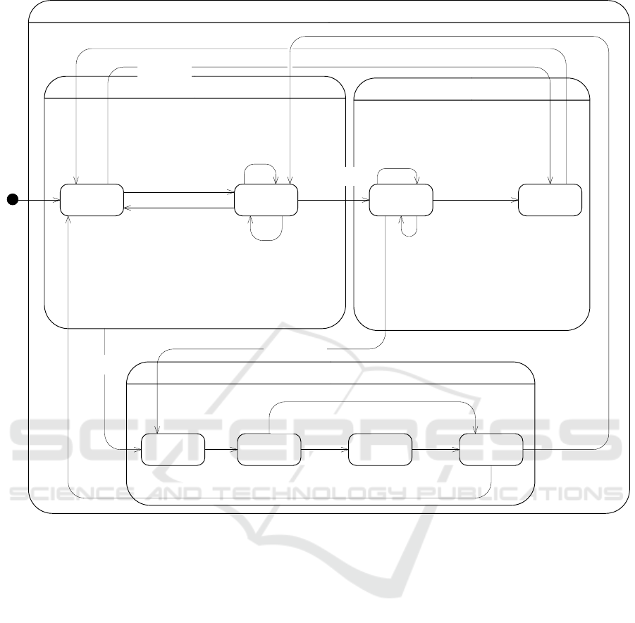
Figure 3: Integrated adaptation and recovery state machine executed by Connector Control.
The Analyzing Failure Events state corresponds
to the analysis activity of MAPE-K where the
recovery connector identifies all transactions that
were interrupted due to service failure. The service
recovery connector determines that a transaction has
failed if either SAQ or SRQ contains a request that
initiates a transaction with the service but neither
RFQ nor RRQ contains a response that completes that
transaction. When failure analysis is completed,
connector control transitions to Planning for
Recovery state.
The Planning for Recovery state corresponds to
the planning activity of MAPE-K where the recovery
connector determines the recovery plan for the failed
transactions. The plan identifies which requests must
be resent to the recovered service so that failed
transactions are restarted at the recovered service.
The recovery plan is determined by executing the
following recovery policy:
• First, the service recovery connector forwards
previous requests of every failed dialog that the
service was engaged in before it failed. These
requests are recovered from SRQ and are
forwarded sequentially in the same order they
were processed before service failure to ensure
that the recovered service also processes these
requests in that order.
• Second, the recovery connector forwards the
requests of failed transactions queued in SAQ,
which contains pending requests that were lost
by the failed service before the service recovery
connector received the responses to these
requests. Note that at this step, if a request that is
being forwarded is of a dialog, then (from the
previous step) the service must have already
received all previous requests of this dialog.
• Third, the recovery connector forwards all
requests in the SPQ, which are new requests that
Integrated Adaptation and Recovery STM
Active
Recovering
Adapting
First Request/
Forward Request
Increment {Active Transaction Count}
First Request/
Forward Request,
Increment {Active Transaction Count}
Intermediate Request, Final Request/
Forward Request
Passivate/
Notify Passivating
Analyzing Failure
Events
Planning For
Recovery
Component
Recovering
Failed/
Notify Failed
Failure Analysis Results
Recovery Plan
[Active Transactions Count > 0]
Reactivate [Active Transactions Count == 0]]/Notify Active
Executing
Recovery
Plan
Restored Lost Messages
Recovery Plan [Active Transactions Count = 0]
Reactivate/
Notify Active
Final Response
[Active Transactions Count = 1]/
Forward Response,
Decrement {Active Transaction Count}
First Response, Intermediate Response/
Forward Response
Final Response [Active Transactions Count > 1]/
Forward Response,
Decrement {Active Transaction Count}
First Response, Intermediate Response/
Forward Response
Final Response [Active Transactions Count > 1]/
Forward Response,
Decrement {Active Transaction Count}
Waiting For
Request
Processing
Passivate/
Notify Quiescent
Final Response
[Active Transactions Count = 1]/
Forward Response,
Decrement {Active Transaction Count},
Notify Quiescent
Passivating
Request/
Forward Request
Quiescent
Failed/Notify Failed
Reactivate [Active Transactions Count > 0]]/Notify Active
Model-based Recovery Connectors for Self-adaptation and Self-healing
83

have been received while the service is in the
recovering state, to the recovered service.
The Executing Recovery Plan state corresponds to the
execution activity of MAPE-K where the recovery
connector restores all requests that must be resent to
the recovered service by moving these requests from
SRQ and SAQ to SPQ, as specified in the recovery
plan. When all requests are restored, Connector
Control transitions to the Component Recovering
state in which the connector waits until the service is
relocated and instantiated by Change Management,
and then has its connection with the recovered service
established. Eventually, when Connector Control
receives the Reactive command, Connector Control
transitions to Active State and notifies Service
Requests Coordinator that the service is active so that
Service Requests Coordinator resumes sending
requests queued in SPQ to Connector Control.
3.5 Service Request Coordinator STM
Based on the discussion in the previous section, the
Service Request Coordinator must forward to
Connector Control certain types of client requests
based on the current state of the service, as shown in
fig. 4. While the service is active (fig. 4), the Service
Request Coordinator forwards all client requests it
receives to Connector Control and also queues these
requests in the SPQ.
When the Service Request Coordinator is notified
that the service is passivating, it transitions to the
Passivating state. The behavior of the Service
Requests Coordinator while in this state is similar to
its behavior in the Active state with one exception: in
the Passivating state, the Service Request Coordinator
does not forward to Connector Control any requests
that initiate a new transaction with the service, and
instead, queues such requests in the SPQ. Eventually,
the Service Request Coordinator is notified that the
service has become quiescent, causing the Service
Request Coordinator to transition to the Quiescent
state. While in the Quiescent state, the Service
Request Coordinator does not forward any requests to
Connector Control and instead queues them in the
SPQ. Finally, when service adaptation is completed,
the Service Request Coordinator receives a
notification from Connector Control that the service
is active, causing the Service Requests Coordinator to
transition to the Active state and to forward all
requests queued in the SPQ to Connector Control.
When service failures occur, the Service Request
Coordinator transitions to the Failed state. While in
the Failed state, the Service Request Coordinator
holds all client requests it receives in the SPQ. The
Service Request Coordinator may also receive
messages from the execution activity of MAPE-K to
restore any client requests that were lost due to
service failure. As a result, the Service Request
Coordinator moves these requests from the SRQ and
the SAQ to the head of the SPQ so that these requests
are resent to the recovered service. Finally, when the
service is recovered, the Service Request Coordinator
forwards all requests stored in the SPQ to Connector
Control and then transitions back to Active state.
4 RECOVERY AND
ADAPTATION PATTERNS
This section describes how the recovery connector
design discussed in the previous section can be used
to handle adaptation and recovery of components in
other architectural patterns (Gomaa, 2011).
Typical client/service communication uses the
Synchronous Message Communication with Reply
pattern, in which the client sends a message to the
service and waits for a response. In the
Asynchronous Message Communication with
Callback pattern, a client sends an asynchronous
request to the service but can continue executing and
receive the service response later. The asynchronous
request sent by the client to the service contains a
callback handle that the service uses when it finishes
processing the client request so that it can send the
response back to the client. A client in this pattern
does not send another request to the service until it
receives a response to the previous request.
Since in this pattern, a client sends one request at
a time to the service, the service recovery connector
(shown in fig. 1) handles requests and responses for
this pattern in the same way as for synchronous
communication with reply. Thus, although the client
behaviour is different, the service behaviour is not.
For this reason, the adaptation and recovery for the
Asynchronous Message Communication with
Callback pattern is handled in the same way as that
described in section 3.4.
In service-oriented architectures, a service
registers its name, location and service description
with a broker, which acts as an intermediary between
the clients and the service. In the Service
Registration pattern, the service initiates a
transaction with the broker by sending it a registration
request containing the service information. The
broker then registers the service and sends an
acknowledgement to the service. The service can also
re-register with the broker if it moves its location,
ICSOFT-EA 2016 - 11th International Conference on Software Engineering and Applications
84

Figure 4: State Machine executed by Service Request Coordinator.
which requires another transaction between the
service and the broker.
From the adaptation and recovery point of view,
this pattern can be treated as a client that
communicates with a service using the Synchronous
Message Communication with Reply pattern. Thus,
the adaptation and recovery patterns for this
architectural pattern are exactly the same as those
described in section 3.4.
After the service has registered with the broker,
clients use the broker to locate the service. In the
Broker Handle pattern, a client sends a request to the
broker to obtain the service’s handle. The broker then
sends a response to the client containing the service’s
handle as a parameter. The client then uses the
service’s handle to interact with the service.
In this pattern, a client initiates two sequential
transactions by first initiating a transaction with the
broker to obtain the service’s handle and then by
initiating a transaction with the service using the
service’s callback handle. As a result, these
transactions can fail and be recovered independently
of each other.
A broker is adapted after it has completed all the
requests it has received, including brokering requests
from clients requesting a handle and service requests
for registration. New requests are held up until the
broker has been relocated. In the case of a broker
failure, all requests it is dealing with are aborted and
only restarted when the broker has been relocated and
instantiated. Both adaptation and recovery are carried
out as described in Section 3.
In service-oriented architectures, the goal is to
increase loose coupling between services so that
instead of services depending on each other,
coordinators are provided for situations where
multiple services need to be accessed, and access to
them needs to be coordinated and/or sequenced.
The coordinator may interact with the services
sequentially and/or concurrently. We consider a
coordinator interacting with multiple services as a
compound transaction that can be broken down into
an atomic transaction between the coordinator and
each service. In this case, when any of the services
fail, the service’s recovery connector restarts a failed
transaction with the service without affecting other
transactions that the coordinator is currently engaged
in with other services. Thus, the recovery and
adaptation patterns for services in this pattern are
exactly the same as discussed in section 3.4.
In the case of a client interacting with a
coordinator, if the coordinator needs to be adapted,
then the entire compound transaction must complete
before adaptation. In the coordinator failure, then the
entire compound transaction is aborted and is only
restarted after the coordinator has been recovered.
5 VALIDATION
This approach of self-healing and self-configuration
was validated by means of detailed simulation of self-
healing and self-configuration scenarios by 1)
executing each scenario, 2) simulating and
monitoring the behavior of the recovery connector
during adaptation or recovery, and 3) resuming the
application from a consistent state after recovery or
dynamic adaptation is completed.
Service Requests Coordinator STM
Quiescent Failed
Notify Passivating
Notify Quiescent
Notify Failed
Notify Active/
Forward Request {for every request in SPQ}
Active Passivating
Intermediate Request, Final Request/
Queue Request {into SPQ},
Forward Request {to Connector Control}
Request/
Queue Request {in SPQ}
First Request/
Queue Request {into SPQ}
First Request,
Intermediate Request, Final Request/
Queue Request {into SPQ},
Forward Request {to Connector Control}
Notify Failed
Request/
Queue Request {in SPQ}
Restore Request/
Dequeue Request {from SAQ or SRQ}
Queue Request {into SPQ}
Notify Quiescent
Notify Active/
Forward Request {for every request in SPQ}
Model-based Recovery Connectors for Self-adaptation and Self-healing
85

Components and connectors in the simulation are
implemented in Java and have a thread of control. In
addition, Java RMI is used as the middleware for
message delivery. The simulation runs on a single
machine. Thus, components are concurrent but
distribution is simulated.
The adaptation and recovery scenarios consist of
simulating adaptation and service failure,
respectively, while three transactions are being
processed. During simulation, every application
message contains in its header (1) a transaction
identifier that uniquely identifies the transaction of
this message, (2) the identifier of the message
producer component, (3) the identifier of the message
consumer component, (4) the timestamp at which the
message producer sent the message, (5) a message
type identifying whether the message initiates a
transaction, completes a transaction, or is an
intermediate message of a transaction, and (6) a
sequence number for detecting duplicate messages.
In the remaining of this section, we use the
notation msg(tid, s, r, ts, p) to represent messages,
where msg can be either request or response, tid is the
transaction identifier of the message, s is the identifier
of message sender, r is the identifier of message
receiver, ts is the timestamp of the message, and p
identifies the message type.
5.1 Recovery Scenario
In the failure scenario, the connector analyzes the
failure and determines which transactions need to be
recovered and sends them to the new service, after the
service has been instantiated on a different node. At
the time of service failure, the execution trace (fig. 5)
revealed that the service was engaged in three
transactions with three clients: two transactions
involving dialogs (transactions c1_1 and c2_1) and
one transaction involving a single request/response
messages (transaction c3_1). At the time of failure,
the execution trace shows that the messages queued
at the connector are as follows:
• SPQ contains no requests that have been received
by the connector but not forwarded to the service.
• SAQ contains three requests (received by the
connector and forwarded to the service):
o request(c2_1, client2, service, 1, begin)
o request(c3_1, client3, service, 1, none)
o request(c1_1, client1, service, 6, end)
• SRQ contains one request (for which a service
response is received at the connector):
o request(c1_1, client1, service, 1, begin)
• RFQ contains one response (received by the
connector but not forwarded yet to the client):
o response(c2_1, service, client2, 6,
intermediate)
• RRQ contains one response (received by the
connector and forwarded to the client)
o response(c1_1, service, client1, 3,
intermediate)
During failure analysis, the execution trace indicates
that the recovery connector determined transactions
c1_1, c2_1, and c3_1 as having failed because none
of them have a response that completes the
transaction in either RFQ or RRQ.
The recovery plan created while the connector is
in the Planning for Recovery state consists of a list
that identifies the messages that must be restored
from the SRQ and the SAQ to recover the failed
transactions. The list obtained from the execution
trace indicates that the first request to be recovered is
request(c1_1, client1, service, 1, begin), which is
queued in the SRQ, since this request was the first
request processed by the service before it failed. The
second request in the list was request(c2_1, client2,
service, 1, begin) queued in the SAQ since this
request was also processed by the service and its
response is queued in the RFQ. The list also contains
actions to recover request(c3_1, client3, service, 1,
none) and request(c1_1, client1, service, 6, end), in
that order, which are queued in the SAQ.
While in the Executing Recovery Plan state, the
connector executed the recovery plan by restoring
messages from the SRQ and the SAQ to the SPQ.
After all messages are recovered, the execution trace
shows that the messages queued in the SPQ (starting
from the head of the SPQ) are as follows:
• request(c1_1,client1,service,1, begin)
• request(c2_1,client2,service,1, begin)
• request(c3_1,client3,service,1, none)
• request(c1_1,client1,service,6, end)
The execution trace also indicates that while the
connector is in the Component Recovering state, it
received a new
request(c4_1, client4, service,1,
none). This request is queued at the tail of the SPQ,
so that it is sent last when the service is recovered.
After the service is recovered, the connector
resumed forwarding requests to the recovered service.
As shown in fig. 5, requests recovered from the SRQ
and SAQ are first resent sequentially, in the same
order specified in the recovery plan. Note that
response(c1_1, service, client1, 3, intermediate) has
already been forwarded to the client before the
service failure, so this response is discarded because
it is a duplicate. Then, new requests queued at the tail
of the SPQ are forwarded to the recovered service.
These requests need not be forwarded sequentially.
At this point, the connector resumes forwarding
requests and responses normally.
ICSOFT-EA 2016 - 11th International Conference on Software Engineering and Applications
86

Figure 5: Fragment of execution trace of simulation for recovery scenario.
5.2 Adaptation Scenario
The goal of the adaptation scenario is to ensure that
the connector behavior handles dynamic service
adaptation without losing requests. In this scenario,
the connector transitions to the passivating state first
before adaptation takes place, until the three
transactions are completed. The execution trace (fig.
6) indicates that Connector Control received the
Passivate command while the service is engaged in
the three transactions. The requests that were
forwarded to the service when the connector
transitioned to the Passivating state are as follows:
• request(c1_1,client1,service,1, begin)
• request(c2_1,client2,service,1, begin)
• request(c3_1,client1,service,1, none)
• request(c1_1,client1,service,6, end)
The execution trace also indicates that the
recovery connector has received and forwarded the
intermediate responses of the first two requests as
follows:
• response(c1_1, service, client1, 3, intermediate)
• response(c2_1, service, client2, 6, intermediate)
Since the service is still engaged in three transactions,
both Connector Control and Service Request
Coordinator transition to the Passivating state, where
the service continues servicing transactions c1_1,
c2_1, and c3_1. The execution trace indicates that
while the Service Request Coordinator is in the
Passivating state, it received request(c4_1, client4,
service,1, none). The action was to hold that request
in the SPQ. However, when the Service Requests
Coordinator received request(c2_1, client2, service,
9, end), it forwarded that request to Connector
Control, since this request must be serviced in order
for the service to become quiescent. Eventually,
Connector Control received all responses to
transactions c1_1, c2_1, and c3_1. At this point, all
active transactions are completed and both Connector
Control and Service Request Coordinator transitioned
to the Quiescent state. When service adaptation is
completed and the connector is reactivated, the
execution trace reveals that the connector forwarded
request(c4_1, client4, service,1, none) queued in the
SPQ to the service and that the connector resumed
execution normally.
5.3 Random Failure and Adaptation
In addition to planned scenarios, our validation
consists of simulating failure and adaptation
occurring at random points during service execution.
The simulation consists of several runs in which the
recovery connector may randomly receive up to 50
dialogs from 50 clients. The service might fail or
receive the Passivate command from Change
Management at a random point during its execution.
As an example, in one run, the service received
the Passivate command while it was processing 9
transactions. Execution trace showed that Connector
Control and Service Requests Coordinator
transitioned to the Passivating state so that the service
continued processing these transactions. In this state,
execution trace shows that the recovery connector
continued forwarding requests of existing
transactions but held requests of new transactions in
Requests forwarded
to and responses
received from
service before
service failure.
Request recovered
from SRQ
Requests recovered
from SAQ
New request held in
SPQ
Model-based Recovery Connectors for Self-adaptation and Self-healing
87

Figure 6: Fragment of execution trace of simulation for adaptation scenario.
the SPQ. When the 9 transactions were processed by
the service, both Connector Control and Service
Requests Coordinator transitioned to the Quiescent
state. After the service was adapted and the recovery
connector reactivated, Connector Control forwarded
41 new requests, which had been previously held in
the SPQ while the service was being adapted. While
processing these transactions, the execution trace
indicates that the service failed. As a result, the
recovery connector recovered the requests of these
transactions, as explained previously in section 3.4.3.
When the service recovered, the recovery connector
restarted the failed transactions with the recovered
service, and then the service continued processing
these transactions normally. At the end of the run, the
execution trace shows that all 50 transactions were
processed and that every client received a response
for every request it had sent.
6 RELATED WORK
Research into self-adaptive, self-configuration, and
self-healing (Garlan et al., 2004; Kramer and Magee,
2007; Menasce et al., 2011; Stojnic et al., 2012)
investigated various automated approaches for
monitoring software systems at run-time and adapting
the software behavior dynamically by changing the
configuration of the software system from one
configuration to another in order to meet certain
system-level constraints and maximize the overall
system utility.
In the area of dynamic software adaptation,
Kramer and Magee investigated how a component
must transition to a quiescent state before safe
adaptation (Kramer and Magee, 1990). Ramirez et al.
discussed various design patterns, including
reconfiguration patterns, for self-adaptive systems
(Ramirez and Cheng, 2010). Gomaa et al discussed
dynamic software adaptation patterns for SOAs
including patterns for different types of service
coordination and distributed transactions (Gomaa et
al., 2010; Gomaa and Hashimoto, 2011, 2012). Li et
al. proposed an adaptable connector that can be used
to reconfigure service connections without affecting
application execution (Li et al., 2006). Irmert et al.
suggest a framework in which service
implementation can be replaced at run-time
transparently and atomically (Irmert et al., 2008).
In the area of self-healing for service-oriented
computing and SOAs, Danilecki et al. suggest a
rollback recovery protocol tailored to the distinctive
characteristics of SOAs (Danilecki et al., 2013).
Candea et al. investigated a platform-dependent
recovery server for J2EE applications using a
modified version of JBoss (Candea et al., 2003). Silva
et al. proposed an automated self-healing software
rejuvenation approach using virtualization where the
focus is to ensure that no messages can be lost due to
software aging and transient faults (Silva et al., 2009).
Salatge et al. suggest the use of fault-tolerance
connectors to increase service dependability in SOAs
(Salatge and Fabre, 2007).
Compared to these approaches, this paper
investigates the problem of integrating adaptation and
recovery patterns for SOAs, which is an area that has
received little attention in the literature. The goal is to
achieve a recovery connector that can be used to
handle both adaptation and recovery of services
Transactions initiated
before connector
received Passivate
command.
Service continued
processing existing
transactions while
passivating.
New transaction is
held in SPQ while
passivating.
New transaction held in SPQ is
forwarded after reactivation.
ICSOFT-EA 2016 - 11th International Conference on Software Engineering and Applications
88

safely and transparently without losing any
application messages. The approach is platform-
independent to increase reuse of these connectors.
7 CONCLUSIONS
This paper has described an approach for self-
configuration and self-healing in which services are
safely adapted at run-time and recovered
transparently from failure to a consistent state using
recovery connectors. Furthermore, the same recovery
connector design is used to handle stateless and
stateful services, in which client requests are
idempotent, in different architectural patterns.
In this research, we consider the atomicity and
consistency properties of transactions (Bernstein and
Newcomer, 2009). Transaction atomicity is achieved
by ensuring that transaction requests and responses
are maintained at the connector for the duration of the
transaction and that no requests can be lost due to
service adaptation or failure. Thus, if a partially
executed transaction is interrupted due to service
failure, it can be restarted. Transaction consistency is
achieved by ensuring that the service always recovers
to a state where lost transaction requests are resent
and redundant messages are detected and removed.
The connector also ensures that previous requests of
a failed dialog are resent to recovered service in the
same order they were processed before failure to
ensure that the recovered service also process these
requests in that order.
Long-living transactions, which contain a human
in the loop, are also supported by our approach since
these transactions can be split into multiple,
independent stateless transactions. In addition, our
approach supports services in which requests are self-
contained. For instance, many web services use
cookies as a state maintenance mechanism. In this
case, the service can be treated as stateless. We are
currently investigating extending our approach to
handle stateful services that handle non-idempotent
client requests, as well as distributed transactions that
involve multiple stateful transactions (e.g. two-phase
commit protocol).
We assume that only a single component can fail
at a time. However in certain types of applications,
such as safety-critical systems, this assumption may
not be acceptable. We are investigating relaxing our
failure assumptions by extending our approach to
handle concurrent node failures. Furthermore, we are
considering tolerating failures occurring at the
recovery connectors by using replication techniques.
Future work includes (1) extending recovery
connectors to handle recovery and adaptation of
other, fully asynchronous architectural patterns such
as the master/slave and control patterns, (2)
incorporating software product line technology to
support multiple recovery strategies for architectural
patterns, (3) investigating recovery in software
systems by incorporating combinations of
architectural patterns, (4) extending the approach to
stateful services that receive non-idempotent
requests, and (5) considering different
communication patterns, including dialogs between
components and distributed transactions.
ACKNOWLEDGEMENTS
This work is partially supported by the AFOSR award
FA9550-16-1-0030.
REFERENCES
Avizienis, A. et al, 2004. Basic concepts and taxonomy of
dependable and secure computing. IEEE Trans.
Dependable Secure Comput. 1, 11–33.
Bernstein, P. A., Newcomer, E., 2009. Principles of
Transaction Processing, Second Edition, 2 edition. ed.
Morgan Kaufmann, Burlington, MA.
Candea, G. et al, O., 2003. JAGR: An Autonomous Self-
Recovering Application Server.
Danilecki, A. et al, P., 2013. Applying Message Logging to
Support Fault-Tolerance of SOA Systems. Found.
Comput. Decis. Sci. 38, 145–158.
Garlan, D. et al, 2004. Rainbow: architecture-based self-
adaptation with reusable infrastructure. Computer 37,
46–54.
Gomaa, H., 2011. Software Modeling and Design: UML,
Use Cases, Patterns, and Software Architectures,
Cambridge University Press, Cambridge ; New York.
Gomaa, H., Hashimoto, K., 2011. Dynamic Software
Adaptation for Service-oriented Product Lines, in:
Proc. of the 15th Int. Softw. Product Line Conf.,
Volume 2, SPLC ’11. ACM, New York, NY, USA, p.
35:1–35:8.
Gomaa, H., Hashimoto, K., 2012. Dynamic Self-adaptation
for Distributed Service-oriented Transactions, in: Proc.
of the 7th Int. Symp. on Softw. Eng. for Adaptive and
Self-Managing Systems, SEAMS ’12. IEEE Press,
Piscataway, NJ, USA, pp. 11–20.
Gomaa, H., Hashimoto, K., Kim, M., Malek, S., Menascé,
D.A., 2010. Software Adaptation Patterns for Service-
oriented Architectures, in: Proc. of the 2010 ACM
Symposium on Applied Computing, New York, NY,
USA, pp. 462–469. doi:10.1145/1774088.1774185
Irmert, F et al., 2008. Runtime Adaptation in a Service-
oriented Component Model, in: Proc. of the 2008 Int.
Model-based Recovery Connectors for Self-adaptation and Self-healing
89

Wkshp. on Softw. Engineering for Adaptive and Self-
Managing Systems, SEAMS ’08. ACM, New York,
NY, USA, pp. 97–104.
Kephart, J. O., Chess, D. M., 2003. The vision of autonomic
computing. Computer 36, 41–50.
Kramer, J., Magee, J., 2007. Self-Managed Systems: an
Architectural Challenge, in: Future of Softw.
Engineering, 2007. FOSE ’07. pp. 259–268.
Kramer, J., Magee, J., 1990. The evolving philosophers
problem: dynamic change management. IEEE Trans.
Softw. Eng. 16, 1293–1306. doi:10.1109/32.60317
Li, G. et al, 2006. Facilitating Dynamic Service
Compositions by Adaptable Service Connectors: Int. J.
Web Serv. Res. 3, 68–84.
Menasce, D., Gomaa, H., Malek, S., Sousa, J. P., 2011.
SASSY: A Framework for Self-Architecting Service-
Oriented Systems. IEEE Softw. 28, 78–85.
doi:10.1109/MS.2011.22
Ramirez, A. J., Cheng, B. H. C., 2010. Design Patterns for
Developing Dynamically Adaptive Systems, in: Proc.
of the 2010 ICSE Wkshp. on Softw. Engineering for
Adaptive and Self-Managing Systems, SEAMS ’10.
ACM, New York, NY, USA, pp. 49–58.
Salatge, N., Fabre, J.-C., 2007. Fault Tolerance Connectors
for Unreliable Web Services, in: 37th Annu. IEEE/IFIP
Int. Conf. on Dependable Systems and Networks, 2007.
DSN ’07. pp. 51–60.
Silva, L. M., Alonso, J., Torres, J., 2009. Using
Virtualization to Improve Software Rejuvenation. IEEE
Trans. Comput. 58, 1525–1538.
Stojnic, N., Schuldt, H., 2012. OSIRIS-SR: A Safety Ring
for self-healing distributed composite service
execution, in: 2012 ICSE Conf on Softw. Engineering
for Adaptive and Self-Managing Systems pp. 21–26.
Taylor, R. N. et al, 2009. Software Architecture:
Foundations, Theory, & Practice, Wiley, Hoboken, NJ.
ICSOFT-EA 2016 - 11th International Conference on Software Engineering and Applications
90
