
Software Theory of the Forbidden in a Discrete Design Space
Iaakov Exman
Software Engineering Dept., The Jerusalem College of Engineering – JCE-Azrieli, Jerusalem, Israel
Keywords: Software Theory, Models, Forbidden Domains, Boundary, Algebra, Eigenvectors, Discrete Design Space.
Abstract: There have been many formulations of “theories” of software systems with a variety of techniques, scopes
and degrees of sophistication. But, one element is almost universally absent in all these theories: a clear
delimitation of what is forbidden in terms of design. This absence is somewhat surprising, as in other
engineering disciplines there are obvious forbidden domains. This paper proposes that in addition to common
quality criteria for scientific theories – such as formality, universality and precision – an acceptable software
theory should clearly demarcate the forbidden in contrast to the possible. This goal is attainable in small and
discrete design space as it limits the amount of subspace search. Algebra is argued to be the mathematical
field suitable to characterize forbidden domain boundaries, in particular using an eigenvectors approach.
Boundaries are illustrated by a case study.
1 INTRODUCTION
Forbidden domains occur in every mature science and
engineering discipline. A famous example in civil
engineering is the Tower of Pisa. Without
reinforcements in this inclined building, it would
continue to increase its angle from its initially vertical
axis until the building would fall and collapse. The
theory of statics – a very old branch of mechanics –
determines what is forbidden, say some distance of
the projection of the center of mass from the building
ground basis.
Another example, from aeronautical engineering,
is the real scenario of an airplane that was flying in a
weather storm region, above the Atlantic Ocean. The
inexperienced pilots, wishing to escape the storm,
tried to climb above the storm causing an increasing
loss of speed, finally resulting in the free fall of the
airplane in the ocean waters. They should have
instead tried to escape the storm from below, while
gaining speed through the airplane descent. Again,
there are clearly forbidden maneuvers for a given
aircraft – dictated by the theory of aerodynamics –
that result in total loss of control.
Software theory also needs forbidden domains in
particular for embedded software, which may cause
critical failures and endanger human life.
1.1 Models of the Possible Are Not a
Theory
UML (Unified Modeling Language) diagrams (UML,
2016) are design models and not a theory. They can
be indefinitely modified by software engineers
developing any software system. They neither impose
any restriction nor point out to any possible design
problems, i.e. they do not have any design quality
criteria associated with them.
The same is even truer about a software system
code in a programming language, say Java or C#.
These languages are not enough abstract to represent
design models with design criteria. Thus, compilers
help in eliminating language syntax bugs, but
otherwise allow indefinite program variations.
1.2 Forbidden Domains Are Essential
for a Software Theory
The main thrust of this paper is the claim that
forbidden domains are essential for a Software
Theory. This is based on the following assumptions:
• Software Composition Problem – a software
theory solves the composition problem of a
hierarchical software system, from subsystems,
down to indivisible components;
• Boundaries of Forbidden Domains – these
boundaries restrict composition variability,
limiting the search effort in design space;
Exman, I.
Software Theory of the Forbidden in a Discrete Design Space.
DOI: 10.5220/0006004601310137
In Proceedings of the 11th International Joint Conference on Software Technologies (ICSOFT 2016) - Volume 2: ICSOFT-PT, pages 131-137
ISBN: 978-989-758-194-6
Copyright
c
2016 by SCITEPRESS – Science and Technology Publications, Lda. All rights reserved
131
• Algebraic Criteria – boundaries are obtained by
algebraic quality of design criteria.
1.3 Organization of the Paper
Section 2 deals with forbidden domains in physical
systems. Section 3 describes the software theory and
Section 4 a general design algorithm with forbidden
domains. In section 5 a design pattern illustrates the
theory. A discussion in section 6 ends the paper.
2 SOURCES OF FORBIDDEN
DOMAINS
Here we deal with sources of forbidden domains for
two physical realms as metaphors hinting to the
software theory.
2.1 Physical Metaphor 1: Slinky
Slinky is a pre-compressed helical spring toy (Slinky,
2016a, b), (see Fig. 1). It can be used for intuitive
demonstrations of physical wave properties.
Assume a slinky is stretched horizontally on a
table by two persons, grasping its end-points. Then
both persons move their hands laterally (in parallel to
the table, perpendicularly to the slinky axis),
generating transverse waves in opposite directions
(each towards the other person). Synchronized
motions obtain standing waves dividing the slinky in
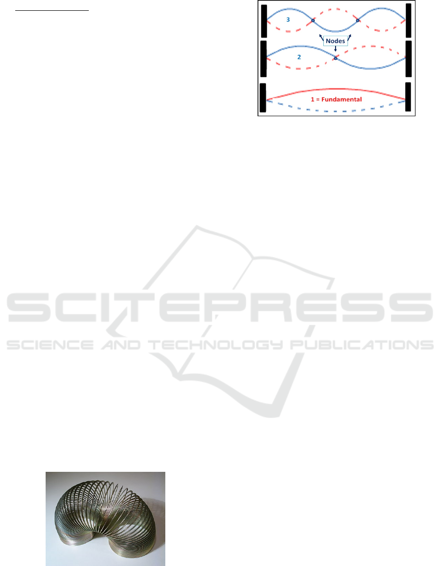
an integer number of equal parts (cf. Fig. 2). Our
conclusions are:
• Boundaries on the slinky behavior – besides the
slinky itself (material and geometry) the
boundaries’ nature (fixed wall or hand motion)
is the most important behavior limitation;
• Forbidden slinky modes – Standing waves are
only obtained for integer number of modes;
fractional modes are forbidden by the mutually
destructive interference of travelling waves.
Figure 1: Slinky – A helical spring, useful to demonstrate
wave properties. This one is made of metal.
Figure 2: Transverse standing waves in a bounded slinky –
The dashed lines show the wave oscillation amplitude in
each slinky point. Three mode kinds are shown. In the
lowest (fundamental) the mode size is the whole slinky
length. The 2
nd
mode is divided into two equal halves. The
next 3
rd
mode is divided into three thirds by two nodes.
2.2 Physical Metaphor 2: Particle in a
Box
The slinky is quite intuitive and its demonstration is
easily reproduced – e.g. dynamic views of standing
waves in (Standing wave 2016a, b). In contrast, our
2
nd
metaphor, demands more specialized physics
knowledge. This should not discourage the reader
who may skip the details that are not essential to grasp
the conclusions of this example.
A particle inside a one-dimensional box is a
simple quantum mechanics’ problem (Messiah,
1961). The particle has mass m. The box has finite
length
, and zero potential. The particle is confined
and cannot escape the two walls with infinite
potential.
This problem is solved by the Schrödinger
equation, an eigenvalue problem of the form:
kkkHv v
λ
⋅⋅= (1)
where
H
is the Hamiltonian operator, and the k
th
eigenvector
kv
fits the eigenvalue k
λ
, standing for an
energy value. As the potential is zero in the box, the
particle Hamiltonian is just a Laplacian. Although the
meaning is different, the solutions’ form, the wave
functions, of this problem (in Fig. 3) is identical to the
slinky modes (in Fig. 2). The wave functions vanish
in the confining walls.
The conclusions are analogous to the slinky ones:
• Boundaries of Particle Behavior – besides the
particle itself (its mass) the boundaries’ nature
(infinite potential in the fixed walls and the box
length
) is the important behavior limitation;
• Forbidden Energy Values – Eigenvectors (wave
functions) have discrete energy values, indexed
by integers; other energy values are forbidden.
ICSOFT-PT 2016 - 11th International Conference on Software Paradigm Trends
132
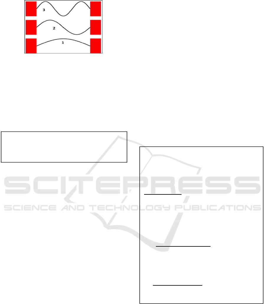
Figure 3: Wave functions of the particle in a one-
dimensional box – Their form is identical to the slinky
modes of Fig. 2.
3 A GENERAL SOFTWARE
THEORY OF THE FORBIDDEN
The basis of our software theory is the general axiom
formulated as follows:
We use here the concept of components in the generic
sense of section 1.2, i.e. as either subsystems or the
smallest indivisible parts of the system.
The Design Space of a software system is larger
than the final design of the software system as the
former contains all the potential components for that
system. The final design of a particular software
system is obtained by searching the Design Space
while limiting the search results by the boundaries of
the forbidden domains.
The Design Space and the final design are both
represented by an algebraic structure such as a matrix
– e.g. the Modularity Matrix (Exman, 2014) or a
Laplacian Matrix (Exman and Sakhnini, 2016) – or a
graph obtained from a matrix – e.g. the Modularity
Lattice (Exman and Speicher, 2015) or a bipartite
graph linked to a Laplacian Matrix.
Our software theory of the forbidden is clearly
hinted by the physical metaphors of section 2. These
are its main characteristics:
a. Boundaries around the software system and its
modules – the boundaries idea is basic to
software, where it is known as encapsulation;
the outer boundary around the software system
separates it from the environment; the inner
boundaries define and separate the system
modules;
b. Forbidden compositions are delimited by
Eigenvectors and module cohesion –
boundaries imply forbidden composition; we
use an eigenvector approach of the chosen
matrices to delimit the forbidden together with a
formal definition of cohesion – see e.g. (Exman,
2015) and (Exman and Sakhnini, 2016); the
final design discrete components are determined
by suitable eigenvector elements;
c. Outliers, in the forbidden areas, are eliminated
by redesign – delimited outliers outside the
module boundaries point out to undesirable
couplings, which should be eliminated by
redesign of the software system.
4 DESIGN ALGORITHM WITH
FORBIDDEN DOMAINS
Here we present in pseudo-code our general
algorithm with boundaries excluding forbidden
domains. It is seen in the next text-box.
This is a general algorithm. In order to actually
apply it to design of a software system, one must
choose a specific matrix type and work with the
suitable specific procedures to select eigenvalues and
to get modules from the eigenvectors.
An example of cohesion calculation is the inverse
of the sparsity of a module (say a sub-matrix). A
typical lower cohesion threshold is 50%. The idea is
that modules should have high-cohesion (low
General Desi
g
n Al
g
orithm – with Forbidden
Domains
Design Space = obtain suitable matrix;
Set lower cohesion threshold;
Search Loop:
While (there are low cohesion modules)
Do {
Obtain matrix eigenvalues/eigenvectors;
Select suitable eigenvalues;
Pick corresponding eigenvectors;
Get modules from eigenvector elements;
Calculate modules’ cohesion;
Forbidden boundary:
If (module cohesion < threshold)
{split module;
Repeat while loop}
Else
End While}
Forbidden domain:
If (outlier left)
{Redesign matrix as needed;}
Axiom – Software System Design Space
The design space of any particular software
system is composed of a finite and discrete
number of components.
Software Theory of the Forbidden in a Discrete Design Space
133
sparsity), while the environment – the matrix
elements outside the modules should have low
cohesion (high sparsity).
5 CASE STUDY: BOUNDARIES
OF THE FORBIDDEN
As a case study we describe here a well-known
software design pattern – the Command pattern – in
terms of UML class diagram, as given in the GoF
(Gang of Four) book (Gamma et al., 1995).
Then, to illustrate the application of the General
Design Algorithm of section 4, we make the following
steps:
a. Obtain a matrix – we choose it to be a
Modularity Matrix to represent the pattern case
study;
b. Get eigenvalues/eigenvectors – using the
suitable approach for the obtained matrix;
c. Obtain the module sizes – from the eigenvector
elements;
d. Illustrate the case of an outlier – by intentional
addition of a matrix element coupling two
modules.
5.1 The Command Design Pattern and
its Class Diagram
The purpose of the Command design pattern is to
decouple an object that invokes an action, say by
clicking a Save, Paste or Print menu-item, from
another object that actually performs the respective
action, viz. to Save, Paste or Print a file. The
Command pattern enables generic command features
such as Undo and Redo independently of the nature
of the specific actions.
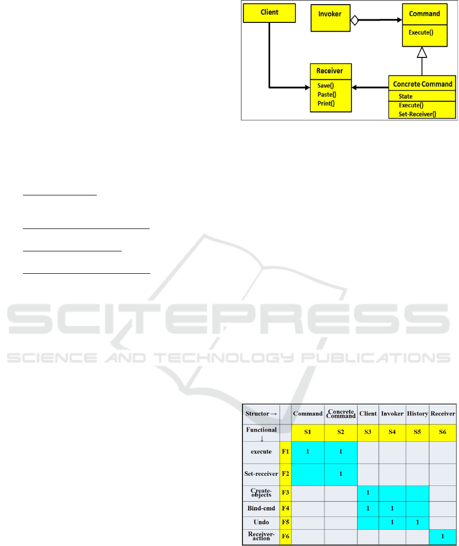
A particular UML class diagram of the Command
design pattern is seen in Fig. 4. It is fashioned after
the class diagram of the Command pattern appearing
in the Motivation section of this pattern in the GoF
book – page 233 in (Gamma et al., 1995).
The Command pattern has an invoker – typically
a menu-item or button – which can be clicked to
activate execution of a command. A Concrete
Command class inherits the abstract Command and
actually executes a specific command, say Paste, on
the Receiver, say a document file.
As already stated in section 1.1, UML is a flexible
design model, allowing indefinite variability for a
specific software system.
Indeed in the Command section of the GoF book
(Gamma et al., 1995) there are four different class
diagrams of the same pattern, besides the fifth generic
Figure 4: A UML Class Diagram of the Command Design
pattern – The invoker is a menu-item, which once clicked
triggers execution of commands. The Concrete-Command
inherits the abstract Command class and actually executes
an action on the Receiver (a document).
diagram of the pattern. One could expect that design
patterns, being offered as reusable software
architectural units, would have some well-defined
standard forms. But there is no notion of a standard
whatsoever. The situation is worsened when one
considers the wider literature on design patterns and
the diverse implementations, in different
programming languages.
5.2 Boundaries: The Modularity
Matrix
We choose the type of matrix to represent our case
study to be a Modularity Matrix (Exman, 2014 and
2012) linking structors (say classes) to provided
functionals (say methods). We could as well choose a
Laplacian Matrix (Exman and Sakhnini, 2016).
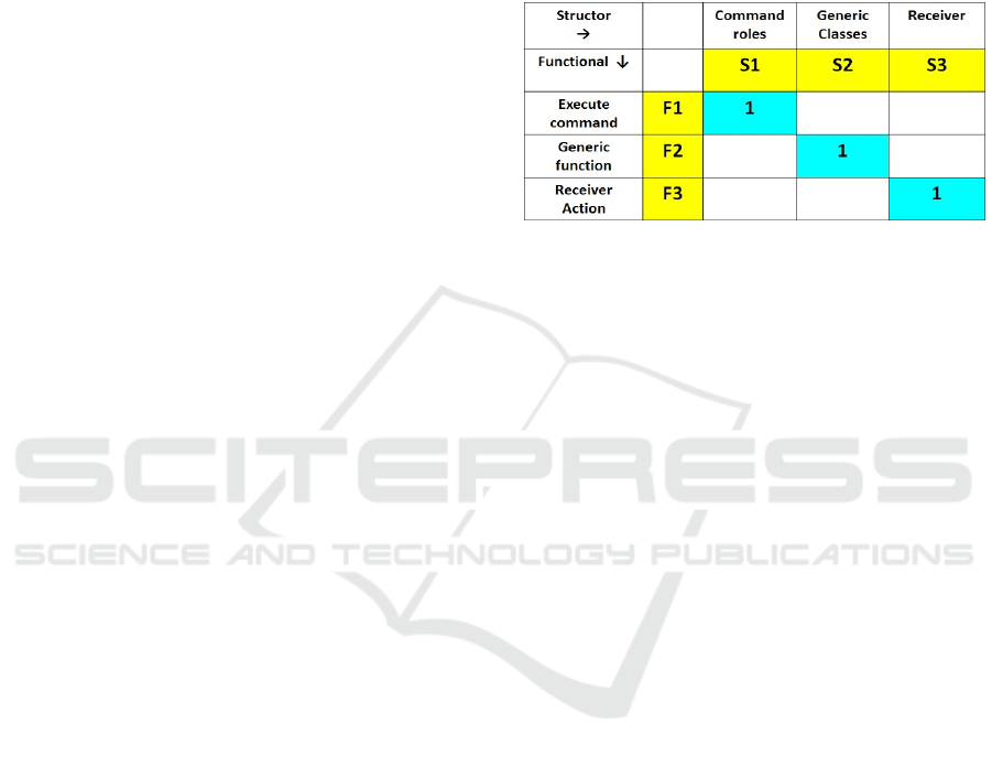
Figure 5: Modularity Matrix of the Command Design
pattern – Structors are columns and functionals are rows.
The matrix is square and block diagonal. Diagonal blocks
(blue background) are modules: top-left the essential
Command pattern roles; middle the generic classes;
bottom-right the Receiver of the action, say a document.
Zero matrix elements are omitted for clarity.
ICSOFT-PT 2016 - 11th International Conference on Software Paradigm Trends
134
The standard form of the Modularity Matrix, by
the linear algebraic theory is a square and block-
diagonal matrix. The Modularity Matrix, containing
only the system structors and functionals, sets a
boundary between the software system and its
environment. There are also well-defined boundaries
among modules, the diagonal blocks. The block-
diagonal Command pattern Modularity Matrix is seen
in Fig. 5.
5.3 Eigenvectors Delimit the Forbidden
A spectral approach has been described to find the
module sizes and eventual outliers in the Modularity
Matrix. The approach is based upon an eigenvector
equation, completely analogous to equation (1) in
section 2.2:
kkk
M
vv
λ
⋅⋅= (2)
M
is a symmetrized and weighted Modularity
Matrix, and the k
th
eigenvector
kv
of
M
corresponds
to its eigenvalue
k
λ
. Details of the symmetrization
and weighting by an affinity expression are not
essential for the understanding of the arguments and
conclusions of this paper. The interested reader may
found more details in (Exman, 2015).
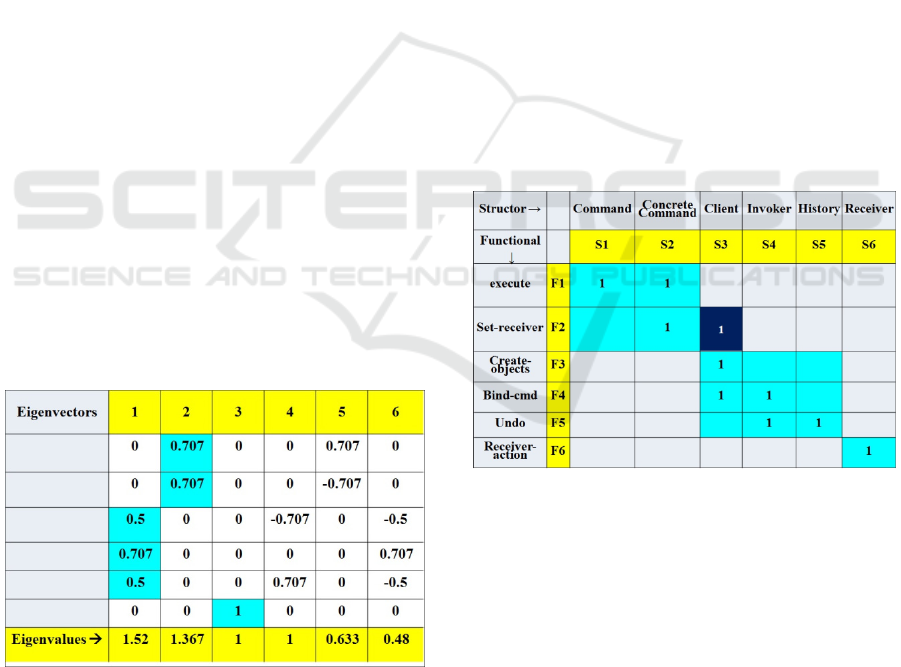
The respective eigenvectors/eigenvalues of the
Command pattern are in Fig. 6. The eigenvalues are
sorted in decreasing order. One clearly perceives that
eigenvector elements in the first three eigenvectors
correspond to the module sizes shown in Fig. 5. The
matrix modules and their eigenvectors can be
reordered as wished.
Figure 6: Command pattern Eigenvectors/eigenvalues –The
3 eigenvectors fitting the first 3 eigenvalues span the
Modularity matrix modules. Positive eigenvector elements
(blue background) tell the module sizes of the matrix in Fig.
5. Here the module sizes fit the eigenvalues’ order.
In case we had chosen a Laplacian Matrix (Exman
and Sakhnini, 2016) to represent our case study, the
specific eigenvalues and eigenvectors would be
different, as well as their particular meaning and the
approach to obtain the module sizes. Again the
specifics of the approach are not essential for the
understanding of the results of this paper. The
important point is that the generic eigenvector
equation (2) would still be valid and relevant.
5.4 Redesign to Eliminate Forbidden
Outliers
In order to illustrate the treatment of existing outliers,
we intentionally add a 1-valued matrix element to Fig.
5, resulting in the matrix in Fig. 7. This added element
– in column S3 and row F2 – is an outlier, as it couples
the upper-left with the middle module, being outside
the borders of both these modules.
The outlier in Fig. 7 is revealed by two means:
1. The eigenvector module size – it fits a large
module of size 5*5 which is the result of
coupling of two modules of sizes 2*2 and 3*3;
2. The cohesion of the large module – is too low,
with many zero-valued elements, and thus must
be split.
Figure 7: Command pattern Class diagram with outlier –
This is the diagram in Fig. 5, with an outlier element added
in in column S3 and row F2 (dark background).
So, the outliers, in forbidden matrix regions, i.e.
outside the diagonal modules, should be eliminated
and the matrix redesigned, according to the General
Design Algorithm in section 4.
6 DISCUSSION
We have shown that, in complete analogy to problem
solution in physical realms, generic formal criteria for
Software Theory of the Forbidden in a Discrete Design Space
135
design quality of software systems are provided by
Linear Algebra, embodied in the theory of Linear
Software Systems. Specifically they are given by
eigenvectors that support system modularity.
Designed artificial systems, be it an airplane or
the software embedded in its computers, behave to a
large extent like natural systems. Citing the words (in
page 7) of Herbert Simon from his book The Sciences
of the Artificial (Simon, 1996): “Given an airplane, or
given a bird, we can analyze them by the methods of
natural science without any particular attention to
purpose or adaptation...”. This is further discussed at
length by Simon in chapter 8 “The Architecture of
Complexity: Hierarchic Systems” of the same book.
6.1 Why Eigenvectors?
Modules reduce a large, possibly complicated,
software system to a small set of sub-systems that are
easier to understand. Thus, blurring modules by
outliers are “forbidden regions” for the software
design goal.
Likewise, eigenvectors reduce and simplify the
vectors needed to describe the whole software
system.
Software system modularity formally means lack
of dependence among different modules. In terms of
matrices – e.g. the Modularity Matrix in Fig. 5 –
modules are mutually independent since each module
is composed by a set of structors (classes) and their
respective functionals (methods) which is disjoint to
the sets of classes of all other modules.
Eigenvectors exactly reflect the modules’ mutual
independence. Eigenvectors – e.g. the first three in
Fig. 6 – are mutually orthogonal, i.e. their pairwise
scalar products are zero, which is a clear-cut
expression of linear independence.
The generality of this approach follows from the
fact that whenever system modularity is a goal, and
the system is represented by a well-defined and
precise matrix, its eigenvectors will reflect the
modules’ mutual independence.
6.2 Search Efficiency Issues
The axiom on the Software System Design Space in
section 3 only tells that the Design Space is finite and
discrete. It does not tell that the Design Space is small,
thus search could take a long time.
Here we provide an intuitive argument for the
claim that, while the overall Design Space for the
whole system may not be small, the Design Space for
each subsystem in any level in the software system
hierarchy is of bounded size.
Let us look again at the Modularity Matrix in Fig.
5. We may collapse each of its three modules into the
higher level of the hierarchy for this system, to obtain
the Modularity Matrix in Fig. 8. This is a 3*3 matrix.
Expanding back this higher level matrix into the next
level, one obtains the matrix in Fig. 5. Looking at
each module in this level one sees that the maximal
size is also a 3*3 matrix.
Figure 8: Collapsed high-level Modularity Matrix of the
Command Design pattern – Modules of Fig. 5 were
collapsed to single matrix elements: top-left the essential
Command pattern roles; middle the generic classes;
bottom-right the Receiver of the action. Zero matrix
elements are omitted for clarity.
Thus, the expectation for a multi-level hierarchy
of a larger system is that in each level the matrix size
of each subsystem (module) is bounded by a small
integer, i.e. design space search is efficient for each
module in all hierarchy levels of the system.
6.3 Related Work
Matrices of several types have been used to analyze
software design, including spectral approaches
applying eigenvectors. These matrices include the
Laplacian matrix (Weisstein, 2016) design structure
matrix (DSM) (e.g. Sullivan et al., 2001) and the
affinity matrix (e.g. a work by Li and Guo, 2012). Due
to space limitations we do not make comparisons
among these matrices and with those in this paper.
The notions of forbidden regions or forbidden
domains have appeared in several contexts in the
literature. We provide here just a limited sample of
papers specifically referring to embedded and pure
software systems. Wu et al. (Wu, 2002) estimate
answer sizes for XML queries by excluding forbidden
regions and assuming some distribution over the
remainder of a two-dimensional diagram. Abbot et al.
(Abbot, 2007) discuss ways of preventing robot
manipulators to enter forbidden regions of a
workspace. Devadas and Aydin (Devadas, 2008)
discuss real-time dynamic power management in
which they explicitly enforce device sleep intervals,
the so-called forbidden regions.
ICSOFT-PT 2016 - 11th International Conference on Software Paradigm Trends
136

6.4 Main Contribution
This position paper claims that real theories of
software systems to be useful for software design –
i.e. to support system modularity – should have clear-
cut criteria of forbidden system compositions. The
forbidden areas if populated would break modularity
by undesired coupling between modules.
REFERENCES
Abbot, J. J., Marayong, P. and Okamura, A. M., 2007.
Haptic Virtual Fixtures for Robot-Assisted
Manipulation, Robotics Research, Vol. 28, Springer
Tracts in Advanced Robotics, pp. 49-64, Springer
Verlag, Berlin, Germany. DOI: 10.1007/978-3-540-
48113-3_5
Devadas, V. and Aydin, H., 2008. Real-Time Dynamic
Power Management through Device Forbidden
Regions, in Proc. IEEE Real-Time and Embedded
Technology and Applications Symposium, pp. 34-44.
DOI: DOI 10.1109/RTAS.2008.21
Exman, I., 2012. Linear Software Models, Extended
Abstract, in Ivar Jacobson, Michael Goedicke and
Pontus Johnson (eds.), Proc. GTSE 2012, SEMAT
Workshop on a General Theory of Software
Engineering, pp. 23-24, KTH Royal Institute of
Technology, Stockholm, Sweden, 2012. Video
presentation:
http://www.youtube.com/watch?v=EJfzArH8-ls
Exman, I., 2014. Linear Software Models: Standard
Modularity Highlights Residual Coupling, Int. Journal
of Software Engineering and Knowledge Engineering,
vol. 24, Issue 2, pp. 183-210. DOI:
10.1142/S0218194014500089
Exman, I., 2015. Linear Software Models: Decoupled
Modules from Modularity Matrix Eigenvectors, Int.
Journal of Software Engineering and Knowledge
Engineering, vol. 25, Issue 8, pp. 1395-1426. DOI:
10.1142/S0218194015500308
Exman, I. and Sakhnini, R., 2016. Accepted for publication
by Proc. ICSOFT’2016, 11
th
Int. Joint Conference on
Software Technologies, Lisbon, Portugal.
Exman, I. and Speicher, D., 2015. Linear Software Models:
Equivalence of Modularity Matrix to its Modularity
Lattice”, in Proc. 10
th
ICSOFT Int. Joint Conference on
Software Technologies, Colmar, France, pp. 109-116,
DOI:10.5220/0005557701090116
Gamma, E., Helm, R., Johnson, R. and Vlissides, J., 1995.
Design Patterns, Addison-Wesley, Boston, MA, USA.
Li, X.-Y. Li and Guo, L., 2012. Constructing affinity matrix
in spectral clustering based on neighbor propagation,
Neurocomputing, Vol. 97, pp. 125-130. DOI:
10.1016/j.neucom.2012.06.023
Messiah, A., 1961. Quantum Mechanics, Vol. I, chapter III,
North-Holland Publishing Co., Amsterdam, Holland.
Reprinted by Dover Publications (2014).
Simon, H. A., 1996. The Sciences of the Artificial, MIT
Press, Cambridge, MA, USA, 3
rd
edition.
Slinky, 2016a. - https://en.wikipedia.org/wiki/Slinky
Slinky, 2016b. Wave Phase changes at fixed end
http://hyperphysics.phy-astr.gsu.edu/hbase/sound/
slinkv.html#c1
Standing wave, 2016a. https://upload.wikimedia.org/
wikipedia/commons/7/7d/Standing_wave_2.gif
Standing wave, 2016b. Standing waves on a Slinky,
http://hyperphysics.phy-
astr.gsu.edu/hbase/sound/slnksw.html#c1
Sullivan, K. J., Griswold, W. G., Cai, Y. and Hallen, B.,
2001. The Structure and Value of Modularity in
Software Design, in Proc. ESEC/FSE 8
th
European
Software Engineering Conf. and 9
th
SIGSOFT Int.
Symp. Foundations Software Engineering, pp. 99-108,
ACM. DOI: 10.1145/503209.503224.
UML, 2015. Specification, OMG (Object Management
Group). http://www.omg.org/spec/UML/
Weisstein, E. W., 2016. Laplacian Matrix, From
Mathworld--A Wolfram Web Resource.
http://mathworld.wolfram.com/LaplacianMatrix.html
Wu, Y., Patel, J. M. and Jagadish, H. V., 2002. Estimating
Answer Sizes for XML Queries, in Jensen, C.S. et al.
(eds.), Advances in Database Technology -
EDBT’2002, LNCS Vol. 2287, pp. 590-608, Springer
Verlag, Berlin, Germany. DOI: 10.1007/3-540-45876-
X_37
Software Theory of the Forbidden in a Discrete Design Space
137
