
A Compliant Actuation Dynamics Gazebo-ROS Plugin for Effective
Simulation of Soft Robotics Systems: Application to CENTAURO Robot
Małgorzata Kameduła, Navvab Kashiri, Darwin G. Caldwell and Nikos G. Tsagarakis
Department of Advanced Robotics, Istituto Italiano di Technologia, Via Morego 30, 16163 Genoa, Italy
Keywords:
Gazebo-ROS Simulators, Legged Robots, Flexible Joint Robots, Series Elastic Actuators, Quadrupeds,
Humanoids, Simulation.
Abstract:
Despite the important role of simulation in the development and control of robotics systems, the majority of
open source simulation tools has however paid no attention to the progress and paradigm change on the robot
design in the past 15 years with the consideration of soft actuation technologies as a mean to power new robotic
systems. More specifically, the integration of series elastic actuators (SEAs) into robots modifies significantly
the dynamics characteristics of the system while the incorporation of the passive compliance into the actuators
is not applied in conventional simulators. This paper introduces a scheme for the implementation of the
SEA dynamics on a Gazebo-ROS framework exploited for the simulation of a new centaur-like robot. This
approach is based on designing a custom control plugin embodying the passive compliance dynamics so that
the controller associated with each joint receives both collocated and non-collocated feedback. A simulation
comparison with Matlab validating the performance of the designed control plugin is demonstrated. In the
end, a whole-body simulation of the centaur robot driven/controlled by the proposed plugin is presented.
1 INTRODUCTION
Simulators, as a necessary mean for the development
of dynamical systems permit the risk-free evaluation
and tuning of new control methods before
implementation on real systems. The increasing
attention paid to robotics during the past four decades
motivated the development of a large number of
simulation tools for this class of dynamic systems.
Furthermore, the communication of a higher-level
architecture with a robot and/or simulator requires
an operating platform capable of incorporating
different control architectures while interacting
with various devices. Hence, numerous middleware
software have being developed amongst which
one may report Robotic Operating System (ROS)
discussed in (Quigley et al., 2009), Yet Another
Robot Platform (YARP) studied in (Metta et al.,
2006), Player introduced in (Kranz et al., 2006), and
Open Robot Control Software (OROCOS) outlined
in (Bruyninckx, 2001). Evaluation of such tools in
terms of performance and practical features such as
supported programming languages is explored in
(Einhorn et al., 2012; Elkady and Sobh, 2012).
According to (Ivaldi et al., 2015), ROS and
YARP are the most commonly employed middleware
software solutions in humanoid robotics. ROS-based
open-source simulators are currently available for the
NAO robots (Forero et al., 2013) and the NimbRO
Open Platform(OP) (Allgeuer et al., 2013). As for the
HUBO (Alunni et al., 2013), a ROS interface with
a real-time control system is exploited to illustrate
the ROS capabilities of providing a communication
layer for the robot. The software architecture of
the iCub robot is developed in YARP. Besides, the
WALK-MAN (Negrello et al., 2016) and COMAN
(Tsagarakis et al., 2013) robots are utilising also a
YARP-based architecture.
Dynamic simulators are mainly classified in
two categories: physics engines and simulating
environments. The former includes light and efficient
libraries solving the system dynamic equations, while
the latter comprises computer programs typically
possessing a graphical user interface, visualisation
features, and various toolboxes. An attempt to
compare different physics engines in an objective
manner was presented in (Erez et al., 2015). In this
group, one can refer to Open Dynamic Engine (ODE),
Open Robotics Automation Virtual Environment
(OpenRAVE), Simbody, Multi-Joint dynamics with
Contact (MuJoCo), and Bullet.
As for the simulating environments, for robotics
one can mention Gazebo, Urban Search And Rescue
simulation (USARSim) described in (Carpin et al.,
Kameduła, M., Kashiri, N., Caldwell, D. and Tsagarakis, N.
A Compliant Actuation Dynamics Gazebo-ROS Plugin for Effective Simulation of Soft Robotics Systems: Application to CENTAURO Robot.
DOI: 10.5220/0006001404850491
In Proceedings of the 13th International Conference on Informatics in Control, Automation and Robotics (ICINCO 2016) - Volume 2, pages 485-491
ISBN: 978-989-758-198-4
Copyright
c
2016 by SCITEPRESS – Science and Technology Publications, Lda. All rights reserved
485

2007), Robot Control Simulator (ROCOS) explained
by (Hirano et al., 2000), Webot described in (Woolley,
1993) and Verosim examined by (Jochmann et al.,
2014). The simulation and software framework
used for legged robots are studied in several works
among which we can report (Tikhanoff et al., 2008)
developed for iCub, (Habra et al., 2015) realized for
COMAN, (Ha et al., 2011) developed for DarwinOP,
(Allgeuer et al., 2013) implemented for NimbRo-OP
and (Asfour et al., 2006) realized for ARMAR-III.
Moreover, a simulator of quadruped BIOSBOT is
detailed in (Guan et al., 2004).
This paper presents a simulator framework for an
under-development SEA actuated centaur-like robot
where the ROS middleware software and Gazebo
simulator are exploited. While the passive dynamics
imposed by the inclusion of SEA has significant effect
on the system behaviour, it is usually neglected since
the dynamics associated with motors is not embedded
in the Gazebo simulator. In this work, we explore
possible solutions and propose a custom control
plugin consisting of the dynamics brought by the
passive compliance, in addition to a given lower-level
control law. Moreover, the customisation of the
control plugin enables the capability of managing
ROS topics to achieve a computationally efficient
communication. The robot linkage representation is
structured in such a way so that the robot is split into
five sections, and the system can operate user-defined
section(s) independently.
The rest of the paper is organised as follows:
Section 2 describes the structure of the Centauro
robot, while Section 3 reports on the dynamics and
control of SEA-driven robots. Section 4 delineates
the architecture of the simulator, including the
modular description of the robot linkage structure,
and the proposed compliant dynamics/control
plugin. Section 5 demonstrates the simulation results
validating the accuracy of the approach propounded
in this work, while Section 6 presents the conclusion.
2 ROBOT DESCRIPTION
The robot discussed in this work is a centaur-like
robot composed of a humanoid upper-body mounted
on quadruped lower-body and powered by SEAs to
exploit physical robustness and high fidelity torque
control characteristics. The upper-body comprises
a dual-arm robotic system with seven degrees of
freedom (DOFs) per manipulator relying mostly upon
an anthropomorphic design as follows: the shoulder
complex is constructed on the basis of a 3-DOF
pitch-roll-yaw arrangement, and it is connected to
Figure 1: A snap-shot from the working simulation for the
centaur robot.
the forearm through an elbow joint. The forearm
apparatus is formed upon a 3-DOF yaw-pitch-yaw
configuration replicating the wrist motions. The
length and mass considered for each of the arms
are about 80 cm and 10 Kg. The lower-body
consists of four 3-DOF legs benefiting from wheels
at the hip and knee joints. The leg kinematics
arrangement is selected according to the spider-like
configuration (Kashiri et al., 2016) as follows: a
3-DOF yaw-pitch-pitch configuration with a total
length and mass similar to those of the arms. The
pelvis base encompassing the first actuator of each
leg is connected to the arms through a 2-DOF torso
composed of a yaw and a pitch joints. Fig. 1 shows
a snap-shot from the simulation environment of the
robot possessing 36 DOFs excluding head and hands.
3 SEA BACKGROUND
For systems powered by SEAs, shown in Fig. 2,
motors do not directly drive the links as the motor
torques are transmitted through compliant elements.
A k−DOF robotic linkage actuated by SEAs therefore
includes 2k DOFs, and the corresponding dynamic
equations are
M(q
q
q)
¨
q
q
q + c
c
c(q
q
q,
˙
q
q
q) + g
g
g(q
q
q) = τ
τ
τ
t
(q
q
q,
˙
q
q
q, θ
θ
θ,
˙
θ
θ
θ), (1)
B
m
¨
θ
θ
θ + D
m
˙
θ
θ
θ + τ
τ
τ
t
(q
q
q,
˙
q
q
q, θ
θ
θ,
˙
θ
θ
θ) = τ
τ
τ
m
, (2)
τ
τ
τ
t
(q
q
q,
˙
q
q
q, θ
θ
θ,
˙
θ
θ
θ) = K
t
(θ
θ
θ − q
q
q) + D
t
(
˙
θ
θ
θ −
˙
q
q
q), (3)
where q
q
q = [q
1
, ..., q
k
]
T
and θ
θ
θ = [θ
1
, ..., θ
k
]
T
are the
link and motor position vectors, respectively, K
t
∈
ℜ
k×k
and D
t
∈ ℜ
k×k
stand for the stiffness and
damping matrices corresponding to passive elements,
τ
τ
τ
t
∈ ℜ
k
refers to the vector of transmission torques
applied by the passive elements, whereas τ
τ
τ
m
∈
ℜ
k
denotes the motor torque vector, B
m
∈ ℜ
k×k
symbolises the motor inertia matrix and D
m
∈
ℜ
k×k
expresses the motor damping matrix. Here,
a collocated-based PD position controller (Tomei,
1991) is used, whose corresponding control law is
described by
τ
τ
τ
controller
= g
g
g(q
q
q
d
) + K
P
(θ
θ
θ
d
− θ
θ
θ) − K
D
˙
θ
θ
θ, (4)
ICINCO 2016 - 13th International Conference on Informatics in Control, Automation and Robotics
486
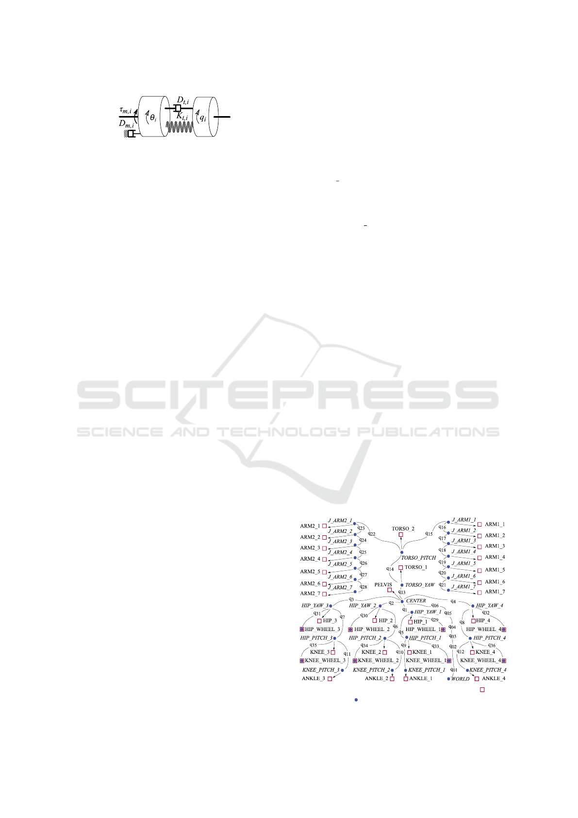
Figure 2: Mechanical model of i−th series viscoelastic
actuator (Kashiri et al., 2014).
where K
P
∈ ℜ
k×k
and K
D
∈ ℜ
k×k
are the proportional
and derivative gain matrices of the controller,
respectively, and θ
θ
θ
d
= q
q
q
d
+ K
−1
t
g
g
g(q
q
q
d
) is the desired
motor position vector extracted from the desired link
position vector q
q
q
d
.
4 SIMULATOR DESIGN
The centaur robot simulation platform exploits the
ROS middleware due to its modularity and the
variety of supported programming languages, while
the simulator is built upon Gazebo software featuring
extensibility through plugins, and choice of the
physics engine; thanks to its open-source architecture.
4.1 Linkage Structure
4.1.1 Robot Linkage Representation
The Unified Robot Description Format (URDF)
representation of the robot is structured according to
the robot description (presented in Section 2), see
Fig. 3, and the Gazebo simulator associated with the
robot linkages is accordingly generated. The robot
structure is represented by means of a tree topology
with a base link at the pelvis centroid. The tree
is constructed on the basis of five branches, four of
which are assigned to legs, while the fifth branch
establishes the upper-body by connecting the torso to
three descendant branches associated with the arms
and the robot head.
4.1.2 System Modularity
As the development of control algorithms can be
facilitated by an initial implementation on a section
of the robot, the robot is structured by five separate
sections: pelvis, torso, arms, legs, wheels; while the
addition of individual wheels to knees and/or hips
can be carried out independently. As a result, apart
from the pelvis as the anchor of the robot structure,
each section can be included or excluded in simulator
and control scheme at will. Nevertheless, when an
ancestor of a section does not spawn, the descendant
branches are disabled automatically. Furthermore,
while the pelvis is connected to a floating-based
system by default, it turns to a stationary base when a
user grounds the pelvis or disables the legs.
4.2 Control Plugin
4.2.1 Multiple Joints Controller
The ‘ros control’ packages provide the controller
interfaces/managers handling the connection between
the ROS platform and the Gazebo software (or the real
hardware). Given a robot with k DOFs, when one uses
the default ‘ros controllers’ packages, the number
of threads concerning the lower-level controller is
2k as each DOF demands a couple of threads for
sending and receiving data. However, for humanoids,
quadrupeds and centaur-like robots, such an approach
results in many threads that are burdensome for a
system to coordinate; as the large number of threads
aggravates system performance and elevates hardware
requirements. To address this problem, we developed
a control plugin dedicating only two threads to
the lower-level controllers of the robot, while
guaranteeing an independent control of individual
joints, besides ensuring the synchronisation of data
sent/received to/from all DOFs.
The control plugin is structured with two
non-real-time ROS topics: the ‘command’ ROS topic,
and the ‘state’ ROS topic. One thread manages the
data transmitted on the former, that includes three
input variables to be subscribed to the controller
associated with each DOF. The other thread takes
care of the data published to the latter, that comprises
a set of output variables. The input variables
are reference position and velocity values as well
as a centralized torque command, and the output
signals are motor-side position and torque states.
Moreover, the plugin incorporates five constant gains
Figure 3: URDF file structure for the centaur robot. – link
centre of mass, – joint frame origin.
A Compliant Actuation Dynamics Gazebo-ROS Plugin for Effective Simulation of Soft Robotics Systems: Application to CENTAURO
Robot
487

Figure 4: rqt graph of simulator depicting system data flow.
for each DOF to be set through the ROS service
and/or through the ROS parameter server during the
controller initialisation
1
. The data flow in the system
is displayed at Fig. 4 showing rqt graph for the
simulation. It can be seen that the simulator operates
two types of control plugins associated with wheels
and compliant joints, named ‘wheel controller’ and
‘flexiblejoint controller’, respectively.
4.2.2 Series Elastic Actuator Module
SEAs drive the centaur robot links, while the
inclusion of compliance into actuation units has not
been yet taken into account in the Gazebo software.
Possible solutions for this deficiency are listed below
1. Addition of an extra DOF per joint replicating
the motor-side dynamics while adding
spring–damper forces to link-side joints;
2. Use of a ‘ros control’ transmission interface;
3. Employment of a Gazebo model plugin;
4. Definition of an independent ROS node
simulating compliant actuators;
5. Incorporation of compliant system dynamics into
a real-time controller module on the basis of
‘ControllerBase’ plugin.
Solution 1, however, doubles the number of
DOFs that increases the computational burden of the
systems with large number of DOFs. As for solutions
2 and 3, apart from the lack of documentations
elaborating their characteristics, they cannot directly
propagate the motor-side states to the controller
while maintaining the minimal control functionality.
Solution 4 imposes an unknown delay to the system
due to the inclusion of a non-real-time node. It
contravenes the synchronisation of the motor-side
and link-side states, that results in instability of
1
Although the control law (4) includes only two gains, the
implementation of other schemes such as (Kashiri et al.,
2014) may require a larger number of gains.
the dynamical system. The data flow between the
afore-stated sources needs to be designed in such a
way so that delays in the data flow that can disturb
the synchronisation of the readings are avoided. As
the ‘ros control’ plugin time is coordinated with the
Gazebo time, and it operates in a real-time module,
solution 5 is therefore selected for the implementation
of the SEA dynamics, and the synchronisation of full
state feedbacks is guaranteed.
4.2.3 SEA Module Development
The implementation of the SEA dynamics in the
control plugin requires a digital form of the
corresponding equations. To this end, (2) and (3)
needs to be discretised. Since the afore-said equations
are related to a set of linear time-invariant systems,
they can be expressed by
¨
θ
θ
θ[n] = B
−1
m
(τ
τ
τ
m
[n] − D
m
˙
θ
θ
θ[n] − τ
τ
τ
t
[n]), (5)
τ
τ
τ
t
[n] = K
t
(θ
θ
θ[n] − q
q
q[n]) +D
t
(
˙
θ
θ
θ[n] −
˙
q
q
q[n]), (6)
when the Euler method is used. Similarly, the
control law, e.g. (4), can also be expressed in a
discrete form from which the motor torque τ
τ
τ
m
can be
derived. The motor-side angular accelerations
¨
θ
θ
θ can
therefore be computed from (5) with the transmission
torque τ
τ
τ
t
given by (6). The motor-side positions and
velocities are thus calculated from the integrations of
the acceleration.
Depending on the stiffness of the passive
compliant element, the dynamics of the system
can evolve in different frequencies. Discrete
representation of such a dynamic system may then
cause numerical instability if the sampling frequency
f
s
used for the discretisation is too low to include
the major dynamics variations. Since the energy
stored in a discrete system within one sample time
is presumed to be constant, the spring motion can
converge to a stable state provided that the sampling
time is sufficiently small to support this assumption.
The simulation of dynamical systems with higher
impedance then requires smaller time steps.
The functionality of the simulator in terms of
stability and accuracy can therefore depend on
the sampling frequency, while it is essential to
set the control loop frequency equal to that of
the real hardware, so that the results extracted
from simulations are comparable with that from
experiments on the robot. On the other hand, the
controller and the actuator dynamics are implemented
at the same thread, and a change in the system
sampling frequency f
s
affects the controller frequency
f
c
, while the later may need to be set lower than the
former. To this end, the control law setting the motor
ICINCO 2016 - 13th International Conference on Informatics in Control, Automation and Robotics
488
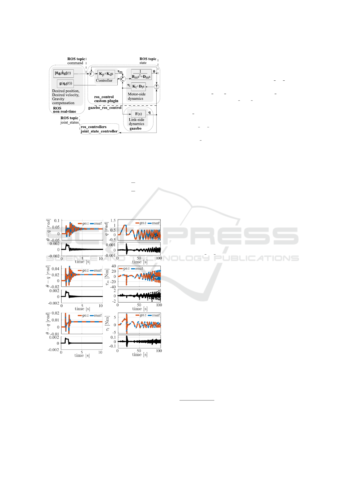
Figure 5: Structure of the SEA module and its integration.
torque is revised in a way that the motor torque τ
τ
τ
m
is updated at a user-defined frequency f
c
. At any
simulation time t, the motor torque is derived from
τ
τ
τ
m
[n] =
(
τ
τ
τ
m
[n − 1] ⇐ t mod(
1
f
c
) > ε
τ
τ
τ
controller
[n] ⇐ t mod(
1
f
c
) < ε
, (7)
where ε is a small constant, and the operator amod(b)
gives the remainder after division of a by b.
Figure 6: On the left – time history of transmission
displacement in step input test: low, medium, and high
stiffness on top, middle, and bottom, respectively. On the
right – results of the time-varying input test: positions on
top, motor torques in the middle, and transmission torques
at the bottom. single line plots below multi line plots show
errors between Matlab and Gazebo-ROS simulation results.
Fig. 5 depicts the structure of the simulator
with the proposed control plugin, in which the
data flow and the role of each part of the
simulation framework are also denoted. The
linkage dynamics (1) is computed by the Gazebo
software, and the real-time ‘gazebo ros control’
bridge sends the link states to the control plugin
and the ‘joint state controller’ from ‘ros controllers’
packages. The ‘joint state controller’ publishes
the data to a non-real-time ROS topic named
‘joint states’ for higher-level control schemes such
as (Ugurlu and Kawamura, 2010). The real-time
‘gazebo ros control’ bridge sends the input torques,
i.e. the transmission torques τ
τ
τ
t
, to Gazebo from
the ‘ros control’ plugin consisting of motor-side
dynamics (2), transmission unit (3), and the controller
(4). The desired motor positions and the gravity
compensation torques are sent to the control plugin
through the non-real-time ROS topic ‘command’,
while the ROS topic ‘state’ receives the motor states.
5 RESULTS
5.1 Comparison with Matlab
To validate the above implementation, a comparison
between the Gazebo-ROS simulation and a Matlab
simulation is presented
2
. To this end, simulation of
the last joint-link of the rrbot manipulator, available
in ‘gazebo ros demos’ repository, when powered by
a SEA is carried out. The controller gains are set
to K
p
= 1000 and K
d
= 0 with a saturation limit of
τ
max
= 33 N. The motor-side inertia and damping
reflected to the link-side through the gearing system
are B
m
= 0.0742 Kg/m
3
and D
m
= 24.768 Nms/rad,
where the motor damping value includes both the
physical damping and the back-EMF effect. The
Matlab simulation was done with a continuous
PD controller when using a fixed-step solver at
1 kHz, and the Gazebo simulation was executed
using the Bullet physics engine with f
c
= f
s
=
1 kHz. The left side of a Fig. 6 illustrates the
evolution of the transmission displacement when
a 1 rad step is sent as the reference trajectory
when the transmission impedance parameters are
set to three impedance sets: K
t
= 100, 188 and
500 Nm/rad with D
t
= 0.3, 0.5 and 1.5 Nms/rad,
respectively. The second simulation comparison is
executed when the reference trajectory is composed
of a 0.1 rad/s ramp, a negative step of 1 rad and a
chirp signal described by 0.5 sin(0.02πt + 0.004πt
2
).
2
Simulations in this work are performed using a laptop with
a processor of Intel
r
Core
TM
i5-5200U 4×2.2 GHz, 8 GB
RAM, and a Graphics card of GeForce 920M.
A Compliant Actuation Dynamics Gazebo-ROS Plugin for Effective Simulation of Soft Robotics Systems: Application to CENTAURO
Robot
489
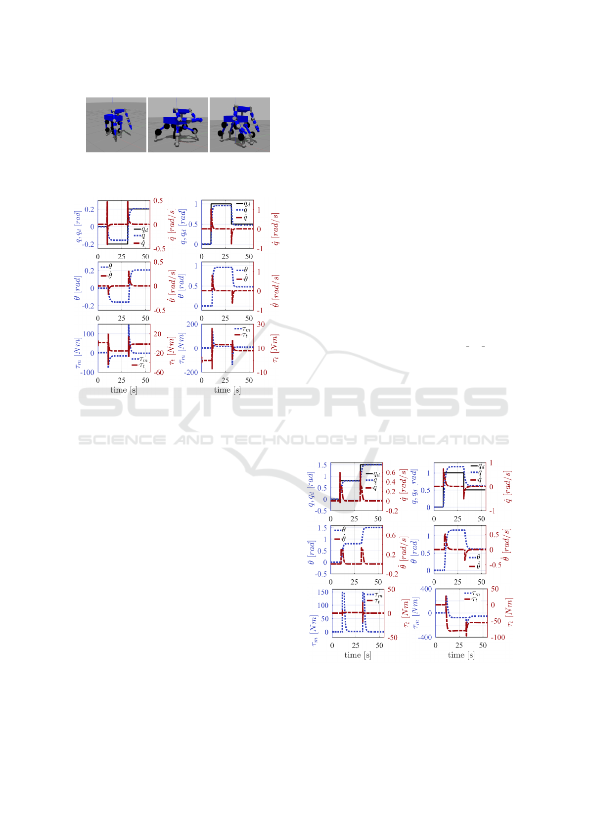
Figure 7: Evolution of centaur robot posture: Initial
configuration, spider-like posture, and mammal-like pose
on the left, middle and right, respectively.
Figure 8: The whole-body simulation results of shoulder
joint (on the left) and elbow joint (on the right): the
reference and actual link positions, and link velocities
on top; the motor positions/velocities in the middle; the
motor/transmission torques at the bottom.
The right part of a Fig. 6 demonstrates the evolution
of positions and torques over time when using two
simulators with the medium stiffness/damping values.
It shows that the ROS-Gazebo simulator reproduces
the Matlab simulator results with 99.9% matching in
link position data when the corresponding maximum
error and the normalized root mean squared error
(NRMSE) are 1.2e-3 and 4.5e-7 rad, respectively.
The transmission torque and motor torque may
instantaneously show differences up to 0.12 and
2.11 Nm, although the corresponding NRMSE values
of 3.6e-5 and 5.3e-4 Nm expresses that such a high
error occurs only in a few moments.
5.2 Whole-body Simulation
A simulation of the whole robot is presented in this
section, when the robot moves from an initial position
to a spider-like posture providing a larger support
polygon and then a mammal-like pose more suitable
for dynamic locomotion, see Fig. 7. The simulation
was executed at f
c
= 1 and f
s
= 2 kHz. Results of the
shoulder pitch and elbow joints of one arm and hip
joints of one leg are illustrated in Fig. 8 and Fig. 9. It
can be seen that joints which are highly loaded by the
gravity exhibit non-negligible steady state position
tracking error resulting from low impedance gains
of the controller. For instance, the hip yaw joint is
not under the gravitational torque, and therefore the
position error can converge to zero, while the pitch
joint presents considerable error.
6 CONCLUSION
This paper presented a simulator for a centaur-like
robot powered by SEAs, utilising a Gazebo-ROS
framework. While the incorporation of passive
elements into the robot actuators using conventional
approaches requires the inclusion of extra DOFs, the
proposed scheme implements the passive dynamics
on the control plugin so that the control scheme can
have access to both motor-side and link-side readings
simultaneously. To this end, the ‘gazebo ros control’
bridge is focused on, and a custom control plugin
is designed in such a way that the dynamics of
motor-side and link-side are synchronised. Moreover,
the proposed approach can be employed to include
the dynamics of variable impedance actuators.
A simulation comparison with Matlab approving
the accuracy of the introduced architecture is
demonstrated. Finally, the proposed control plugin is
exploited in the simulation of the CENTAURO robot.
Figure 9: The whole-body simulation results of hip yaw
joint (on the left) and hip pitch joint (on the right). The
arrangement of variable are similar to that noted in Fig. 8.
ICINCO 2016 - 13th International Conference on Informatics in Control, Automation and Robotics
490

ACKNOWLEDGEMENTS
This project has received funding from the European
Unions Horizon 2020 research and innovation
programme under grant agreement No 644839
(CENTAURO).
REFERENCES
Allgeuer, P., Schwarz, M., Pastrana, J., Schueller, S.,
Missura, M., and Behnke, S. (2013). A ROS-based
software framework for the NimbRo-OP humanoid
open platform. In IEEE-RAS Int. Conf. Humanoid
Robot Work. Humanoid Soccer Robot.
Alunni, N., Phillips-Grafflin, C., Suay, H. B., Lofaro,
D., Berenson, D., Chernova, S., Lindeman, R. W.,
and Oh, P. (2013). Toward a user-guided
manipulation framework for high-DOF robots with
limited communication. IEEE Conf. Technol. Pract.
Robot Appl. TePRA, 7(3):121–131.
Asfour, T., Regenstein, K., Azad, P., Schr
¨
oder, J.,
Bierbaum, A., Vahrenkamp, N., and Dillmann,
R. (2006). ARMAR-III: An integrated humanoid
platform for sensory-motor control. In IEEE-RAS Int.
Conf. Humanoid Robot., pages 169–175.
Bruyninckx, H. (2001). Open robot control software: the
OROCOS project. In IEEE Int. Conf. Autom. Robot.,
volume 3, pages 2523–2528.
Carpin, S., Lewis, M., Wang, J., Balakirsky, S., and
Scrapper, C. (2007). USARSim: A robot simulator
for research and education. In IEEE Int. Conf. Robot.
Autom., pages 1400–1405.
Einhorn, E., Langner, T., Stricker, R., Martin, C., and
Gross, H. M. (2012). MIRA - Middleware for robotic
applications. In IEEE Int. Conf. Intell. Robot. Syst.,
pages 2591–2598.
Elkady, A. and Sobh, T. (2012). Robotics Middleware:
A Comprehensive Literature Survey and
Attribute-Based Bibliography. J. Robot., 2012.
Erez, T., Tassa, Y., and Todorov, E. (2015). Simulation
tools for model-based robotics: Comparison of Bullet,
Havok, MuJoCo, ODE and PhysX. In IEEE Int. Conf.
Robot. Autom., pages 4397–4404.
Forero, L. L., Y
´
anez, J. M., and Ruiz-del Solar, J. (2013).
Integration of the ros framework in soccer robotics:
the nao case. In Rob. 2013 Robot World Cup XVII,
pages 664–671.
Guan, X., Zheng, H., and Zhang, X. (2004). Biologically
inspired quadruped robot biosbot: modeling,
simulation and experiment. In IEEE Int. Conf. Auton.
Robot., pages 261–266.
Ha, I., Tamura, Y., Asama, H., Han, J., and Hong, D. W.
(2011). Development of open humanoid platform
DARwIn-OP. In SICE Annu. Conf. 2011, pages
2178–2181.
Habra, T., Dallali, H., Cardellino, A., Natale, L., and
Tsagarakis, N. (2015). Robotran-Yarp interface : a
framework for real-time controller development based
on multibody dynamics simulation. In ECCOMAS
Themat. Conf. Multibody Dyn., pages 2–3.
Hirano, T., Sueyoshi, T., and Kawamura, A. (2000).
Development of ROCOS (Robot Control
Simulator)-Jump of human-type biped robot by
the adaptive impedance control. In Proc. 6th Int.
Work. Adv. Motion Control, pages 606–611.
Ivaldi, S., Peters, J., Padois, V., and Nori, F. (2015). Tools
for simulating humanoid robot dynamics: A survey
based on user feedback. In IEEE-RAS Int. Conf.
Humanoid Robot., pages 842–849.
Jochmann, G., Bl
¨
umel, F., Stern, O., and Roßmann,
J. (2014). The Virtual Space Robotics Testbed:
Comprehensive Means for the Development and
Evaluation of Components for Robotic Exploration
Missions. KI - K
¨
unstliche Intelligenz, 28(2):85–92.
Kashiri, N., Ajoudani, A., Tsagarakis, N. G., and Caldwell,
D. G. (2016). Evaluation of Hip Kinematics Influence
on the Performance of a Quadrupedal Robot Leg. In
Int. Conf. Informatics Control. Autom. Robot.
Kashiri, N., Tsagarakis, N. G., Van Damme, M.,
Vanderborght, B., and Caldwell, D. G. (2014).
Enhanced Physical Interaction Performance for
Compliant Joint Manipulators using Proxy-based
Sliding Mode Control. In Int. Conf. Informatics
Control. Autom. Robot., pages 175–183.
Kranz, M., Rusu, R., Maldonado, A., and Beetz, M. (2006).
A player/stage system for context-aware intelligent
environments. Proc., 6:17–21.
Metta, G., Fitzpatrick, P., and Natale, L. (2006). YARP:
Yet another robot platform. Int. J. Adv. Robot. Syst.,
3(1):043–048.
Negrello, F., Garabini, M., Catalano, M., Kryczka, P.,
Choi, W., Caldwell, D., Bicchi, A., and Tsagarakis,
N. (2016). Walk-man humanoid lower body design
optimization for enhanced physical performance. In
IEEE Int. Conf. Robot. Autom., pages 1817–1824.
Quigley, M., Conley, K., Gerkey, B., Faust, J., Foote, T.,
Leibs, J., Wheeler, R., and Ng, A. Y. (2009). ROS: an
open-source Robot Operating System. In ICRA Work.
open source Softw., volume 3, page 5.
Tikhanoff, V., Cangelosi, A., Fitzpatrick, P., Metta, G.,
Natale, L., and Nori, F. (2008). An Open-Source
Simulator for Cognitive Robotics Research : The
Prototype of the iCub Humanoid Robot Simulator. In
Work. Perform. Metrics Intell. Syst., pages 57–61.
Tomei, P. (1991). A Simple PD Controller for Robots
with Elastic Joints. IEEE Trans. Automat. Contr.,
36(10):1208–1213.
Tsagarakis, N. G., Morfey, S., Cerda, G. M., Zhibin, L., and
Caldwell, D. G. (2013). Compliant humanoid coman:
Optimal joint stiffness tuning for modal frequency
control. In IEEE Int. Conf. Robot. Autom., pages
673–678.
Ugurlu, B. and Kawamura, A. (2010). Bipedal walking
trajectory generation based on ZMP and Euler’s
equations of motion. In IEEE-RAS Int. Conf.
Humanoid Robot., pages 468–473.
Woolley, B. (1993). Virtual Worlds. In Virtual Worlds,
volume 1434, pages 254–263. Springer.
A Compliant Actuation Dynamics Gazebo-ROS Plugin for Effective Simulation of Soft Robotics Systems: Application to CENTAURO
Robot
491
