
Virtualizing Service Infrastructure with Hardware Gateway in
Data Center
Junji Kinoshita
1
and Norihisa Komoda
2
1
Center for Technology Innovation, Information and Telecommunications, Hitachi, Ltd., Yokohama, Japan
2
Codesolution, K.K., Osaka, Japan
Keywords: Cloud, Data Center, Network Virtualization, VXLAN, Gateway.
Abstract: Service providers have been struggling with service infrastructure management in their data centers like
taking care of excess or shortage of physical resources. To solve the issue, we propose virtualization of
service infrastructure by connecting physical resources with hardware gateway and virtualize network
traffic among physical resources. With this approach, service providers can make their service infrastructure
more flexible and dynamically change service infrastructure configuration like adding or removing physical
resources on demand.
1 INTRODUCTION
As more and more enterprise companies and
organizations have been using IT services like cloud
computing service, service providers have been
facing challenges to achieve higher resource
utilization and scalability in their data centers to
make them competitive in the service market.
However their data centers are becoming “siloed”
environment where resources are physically divided
into service infrastructures (silos) rather than a
single flat resource pool. This is because scalability
limitations of components used in each service
infrastructure (silo), like specification maximums of
server virtualization software, network and storage
system. As a result, service providers are struggling
to improve resource utilization and scalability.
To mitigate this situation, network virtualization
has been tried in service providers’ data centers in
the last several years so that service users’ network
can be expanded among different silos. But silos still
exist and their sizing, configuration changes and
operation are still tough problems.
To solve these problems caused by silos, we
propose virtualizing silos themselves by using
hardware gateway. Virtualizing silos and using
server virtualization inside silos could cause
management complexity. We introduce the 2 layered
hierarchy where each can focus on user service and
resource service respectively.
2 OVERVIEW OF CHALLENGES
OF CURRENT DATA CENTER
2.1 Overview of Data Center Network
In the IaaS (Infrastructure as a Service) service
infrastructure, server virtualization software has
been widely used where the server virtualization
manager software manages hypervisor software on
physical servers (hypervisor host), deploys Virtual
Machines (VM) on hypervisor hosts and moves
VMs among hypervisor hosts (live migration). The
logical network separation technology like VLAN
(Virtual LAN) is used to isolate VM network traffic
for multi-tenancy and shared storage system is used
to store VM images so that VMs can be moved
among hypervisor hosts. There are commercial and
open source server virtualization and IaaS software
like VMware vSphere, Microsoft Hyper-V,
OpenStack and so forth (see the Reference Section).
In such an environment, service infrastructure
cannot scale well and has to be divided into silos
because there are scalability limitations in server
virtualization software, network and shared storage
system. For example, server virtualization software
has configuration maximums based on software
specification. Some of them are explicit and
documented, but some are not and realized only in
real practice. Even different versions of the same
server virtualization software sometimes cannot
Kinoshita, J. and Komoda, N.
Virtualizing Service Infrastructure with Hardware Gateway in Data Center.
DOI: 10.5220/0005999100950098
In Proceedings of the 13th International Joint Conference on e-Business and Telecommunications (ICETE 2016) - Volume 1: DCNET, pages 95-98
ISBN: 978-989-758-196-0
Copyright
c
2016 by SCITEPRESS – Science and Technology Publications, Lda. All rights reserved
95
work together and a service provider has to manage
different versions respectively. When a service
provider has a multi-vendor policy and uses different
types of server virtualization software to avoid
vendor lock-in, it is likely that they cause inter-
connectivity problem as well. Even if a service
provider tries to make homogeneous infrastructure,
technology and software evolve and change day by
day and result in heterogeneous infrastructure.
Network also has its scalability limitation like the
maximum number of VLANs. Share storage system
has I/O maximum as well. Even worse, when a
service provider tries to provide a wide variety of
services like IaaS, managed service, PaaS (Platform
as a Service) and SaaS(Software as a Service), they
often have to separate each service infrastructure
because of difference among service requirements.
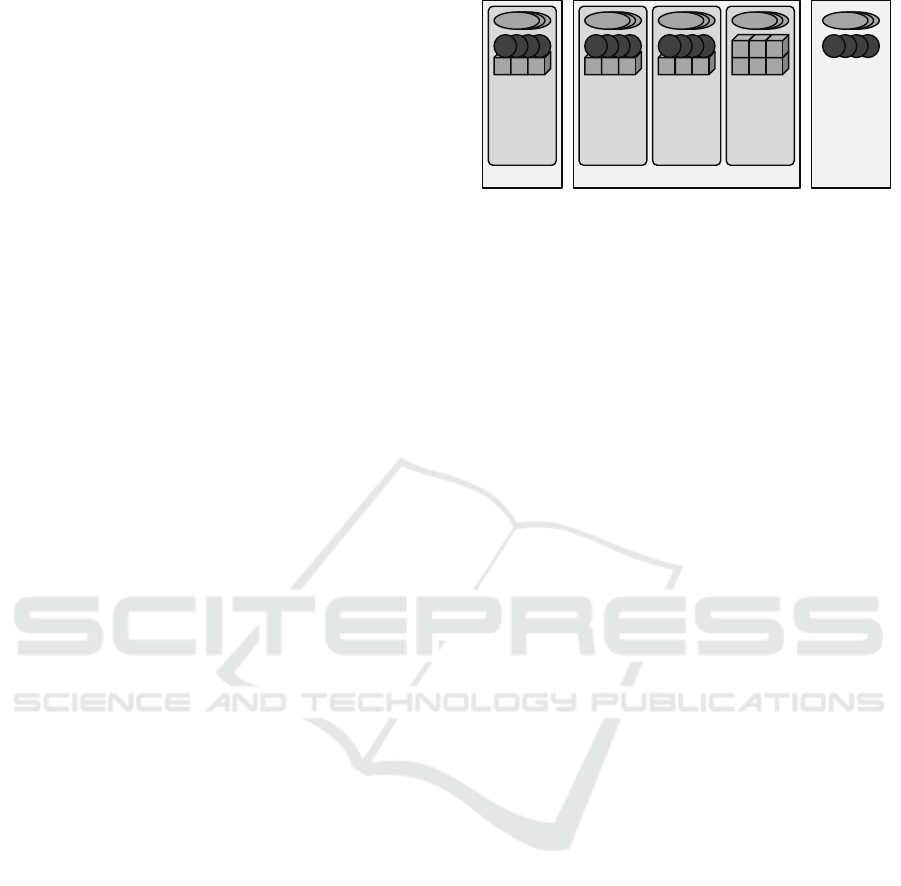
As a result, service provider data center in a real
environment is not a flat resource pool. It is divided
into many silos as shown in Figure 1. In this
example, a service provider data center consists of 3
silos where two of them provide IaaS but use
different versions of server virtualization software,
and one of them provides bare metal service and
does not use server virtualization. Sometimes a silo
is called a zone, an island and so forth. In a large
data center, there might be even hierarchy among
silos. A silo can be a rack or multiple racks.
As service users increase or decrease, service
providers have to take care of shortage or excess of
resources in a silo. And as services grow or decline,
service providers have to take care of expansion or
shutdown of a silo as well. However, service
providers cannot easily change silo configuration
because a silo is a group of physical resources like
servers. Changing the size of a silo, creating and
destroying a silo require a lot of cost.
In these situations, service providers need
workarounds. For example, they need to expand a
user system to a different silo in case of resource
shortage. They also need to migrate a user system
from an outdated old silo to a new one. And they
might have to expand a user system across different
service silos to meet user’s requirements. Because
silos are problems in service infrastructure behind
the scene, service providers cannot enforce their
users to change network configuration like IP
addresses when users’ system have to go beyond a
silo. So, extending user network across silos in
Layer2 (L2) has been required so that users don’t
have to change network configuration (L2
extension). To realize L2 extension, user network
virtualization has been tried in the last couple of
years (Ben Pfaff et al., 2009).
Figure 1: Overview of Data Center.
2.2 User Network Virtualization
An overlay network virtualization technology like
VXLAN (Virtual eXtensible LAN), NVGRE
(Network Virtualization using Generic Routing
Encapsulation) and STT (Stateless Transport
Tunneling) has emerged in the market in the last
couple of years to realize user network virtualization.
The overlay network virtualization uses
encapsulation of L2 traffic among virtualization
endpoints called VTEP (Virtual Tunnel End Point)
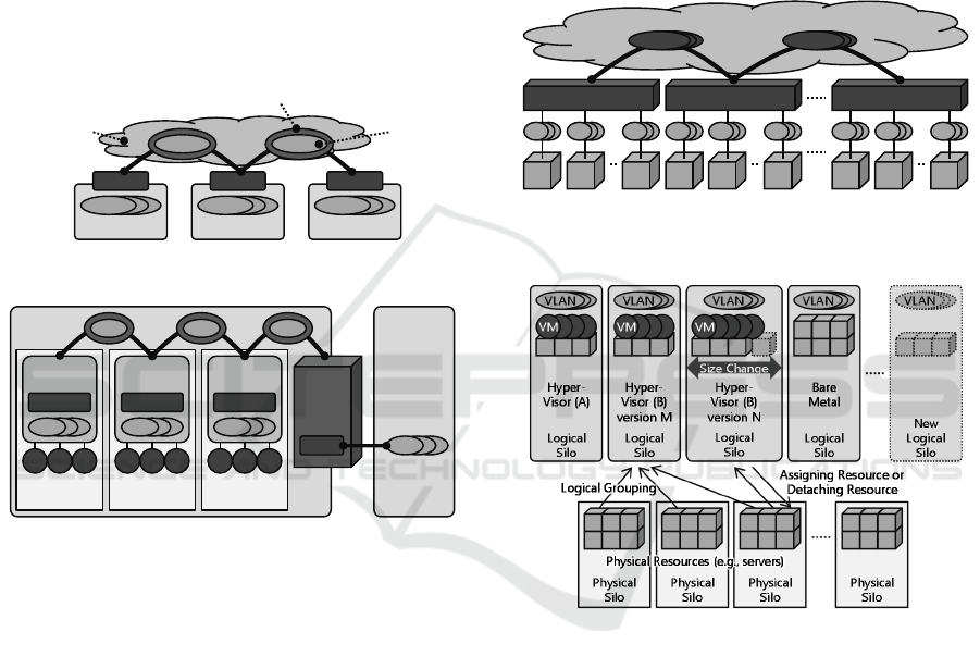
as shown in Figure 2. In this example, each VTEP is
placed on different L2 network (e.g., VLAN)
domain. VTEPs are connected via existing L3
network, and encapsulates L2 network and transfers
them to other VTEPs. Because the overlay network
virtualization is based on L2 over Layer3 (L3), a
large L2 inter-silo network is not required and thus
inter-silo network can be flexible. And it can
connect multiple silos using multicast or meshed
tunnels.
In the market, software-based overlay network
virtualization is popular that implements a VTEP
function in a virtual switch on a hypervisor host as
shown in Figure 3. In this example, virtual switch
software with VTEP function is on each hypervisor
host, encapsulate L2 traffic of VMs and transfers
them to other virtual switches. When it comes to
connectivity between a software-based overlay
network virtualization environment and a legacy
non-virtualized environment, hardware gateway can
be used. Some hardware gateway products like a
VXLAN Gateway are already available in the
market. The software-based implementation is likely
to be integrated with server virtualization. With this
tight integration, software-based implementation can
deploy virtual networks along with VMs deployment.
The user network virtualization using the overlay
network virtualization allows service providers to
realize L2 extension among silos. However, it is just
a workaround in case of resource shortage and user
system migration. And it works only for silos that
use the same server and network virtualization
Customer DC
Silo
VLAN
Hyper-
Visor (A)
Service Provider DC
Silo
VLAN
Hyper-
Visor (B)
version M
Silo
VLAN
Hyper-
Visor (B)
version N
Silo
VLAN
Partner DC
subnet
VM
Bare
Metal
VM VM VM
Servers Servers Servers Servers
DCNET 2016 - International Conference on Data Communication Networking
96
software. Service providers still have to take care of
situations like excess of resources in a silo, and
expansion or shutdown of a silo. It is difficult for
service providers to forecast service demand and
estimate how many resources would be necessary in
advance. In case excess of resources happens in a
silo, it directly affects service providers’ cost. And
even though another silo is running out of resources,
user network virtualization might be impossible
because another silo is not using the same server and
network virtualization software. In that case, moving
resources from one silo to the other is costly, time-
consuming and might cause miss-operation because
resources are physical.
Figure 2: Overlay Network Virtualization.
Figure 3: Software-based Overlay Network Virtualization.
3 SILO VIRTUALIZATION
3.1 Gateway-based Silo Virtualization
To solve problems caused by silos, we propose
virtualization of an entire silo. We cannot eliminate
silos because service infrastructure components like
server virtualization software, network and storage
system have scalability limitations. However, we
can solve problems by virtualizing silos and thus
making silos flexible.
Because a silo is a group of physical resources,
we cannot use software-based approach like server
virtualization or software-based overlay network
virtualization. Instead, we connect physical
resources each other using a hardware gateway like
a VXLAN Gateway and virtualize network traffic
among those physical resources as shown in Figure
4. In this example, physical resources like servers
are connected to VXLAN Gateways. Each VXLAN
Gateway encapsulates L2 traffic of physical
resources and transfers them to other VXLAN
Gateways. Even if a silo uses multiple VLANs,
those VLANs are virtualized using VXLAN and
connected among physical resources that belong to
the same silo. In case a silo uses software-based
overlay network virtualization, it is just L3 traffic
from the gateway perspective and can be virtualized
among physical servers that belong to the same silo.
Figure 4: Connecting Physical Resources via Gateway.
Figure 5: Silo Virtualization.
With this approach, a silo is still a group of
physical resources but the grouping becomes logical.
We can define a silo using physical resources that
are not necessarily placed next to each other. For
example, we can have a silo from physical servers
from different racks. This allows service providers
to dynamically change the size of silos, create a new
silo, destroy an old silo and thus, make silos flexible
as shown in Figure 5. In this example, a physical silo
is a rack, multiple racks, a floor or a data center, and
contains multiple physical resources like servers.
Each logical silo is defined as a logical group of
physical resources from different physical silos.
When service in a logical silo grows and needs more
physical resources, those physical resources are
chosen from different physical silos and assigned to
L2 Networks
L2
VTEP
L2 Networks
L2
VTEP
L2 Networks
L2
VTEP
L2 L2
Original
Traffic
Existing
L3 Network
VXLAN (Encapsulated Traffic)
Silo
Silo
Hypervisor
Host
VM VM VM
Gateway
VTEP L2
Non-
Virtualized
Legacy
Environment
Hypervisor
Host
VM VM VM
Hypervisor
Host
VM VM VM
Virtual
Switch
VTEP
L2
Virtual
Switch
VTEP
L2
Virtual
Switch
VTEP
L2
L2 L2 L2
L2
VXLAN Gateway
L2L2
Physical Resources
(e.g., servers)
Existing L3 Network
L2L2L2 L2L2L2 L2
VXLAN Gateway
L2L2
Physical Resources
(e.g., servers)
L2L2L2 L2L2L2 L2
VXLAN Gateway
L2L2
Physical Resources
(e.g., servers)
L2L2L2 L2L2L2
VXLANVXLANVXLANVXLANVXLANVXLAN
Virtualizing Service Infrastructure with Hardware Gateway in Data Center
97
the logical silo by changing VXLAN Gateway
configurations. When service in a logical silo does
not go well as expected and does not need physical
resources any more, those physical resources are
detached from the logical silo and returned to
physical silos. Thus, service infrastructure become
flexible and service providers do not have to
precisely estimate sizing of service infrastructure.
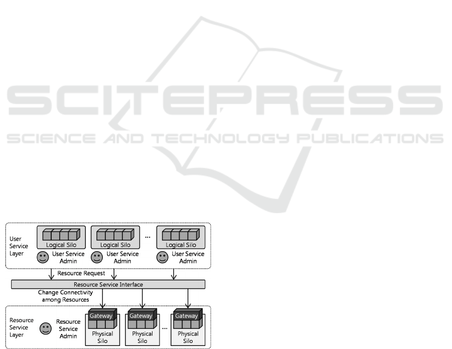
3.2 Hierarchical Architecture
Silo virtualization could cause management
complexity. For example, there might be software-
based server virtualization and overlay network
virtualization in a virtualized silo. To mitigate the
management complexity in a data center, we use a 2
layered hierarchical architecture as shown in Figure
6. The upper layer is “User Service” layer where
service providers provide services to users using
virtualized silos. The lower layer is “Resource
Service” layer where resource provider provides
physical resources to service providers in the upper
layer. We set the resource service interface between
them. When a user service provider has excess or
shortage of physical resources, starts a new service,
or shutdown an existing service, the user service
provider can request the resource service provider to
give or return physical resources through the
resource service interface. Based on those requests,
the resource service provider can manually or
automatically change silo configuration only by
changing connectivity among physical resources
with VXLAN Gateways. This allows user service
providers to focus on their services for users, the
resource service provider to focus on managing
physical resources that are independent from
software used by user service providers.
Figure 6: Hierarchical Architecture.
4 CONCLUSIONS
We proposed virtualization of service infrastructure
(silo) in data center. A basic prototype system has
been developed based on our approach using
commercial hardware VXLAN gateways where a
couple of physical silos are connected through
gateways. And we are evaluating the effectiveness
and drawbacks on our approach.
Our approach can help service providers deal
with situations like excess or shortage of resources,
and expansion or shutdown of a silo. And this also
allows service providers to make their data centers
more flexible with hierarchical architecture.
REFERENCES
“802.1Q - Virtual LANs,” http://www.ieee802.org/
1/pages/802.1Q.html, IEEE, last visited 2016-01-13.
“vSphere,” https://www.vmware.com/products/vsphere,
last visited 2016-01-13.
“Hyper-V,” http://www.microsoft.com/en-us/server-cloud/
solutions/virtualization.aspx, last visited 2016-01-13.
“OpenStack,” https://www.openstack.org/, last visited
2016-01-13.
Ben Pfaff, Justin Pettit, Teemu Kopenen, Keith Amidon,
Martin Casado and Scott Shenker, 2009, “Extending
Networking into the Virtualization Layer,” ACM
SIGCOMM Workshop on Hot Topics in Networking
(HotNets).
“Virtual eXtensible Local Area Network (VXLAN): A
Framework for Overlaying Virtualized Layer 2
Networks over Layer 3 Networks,” https://
tools.ietf.org/html/rfc7348, IETF, RFC7348, 2014.
“NVGRE: Network Virtualization Using Generic Routing
Encapsulation,” https://tools.ietf.org/html/rfc7637,
IETF, RFC7637, 2015.
“A Stateless Transport Tunneling Protocol for Network
Virtualization (STT),” https://tools.ietf.org/html/draft-
davie-stt-06, IETF, 2014 last visited 2016-01-13.
DCNET 2016 - International Conference on Data Communication Networking
98
