
Automatic Testbench Generation for Simulation-based Verification of
Safety-critical Systems in UML
Ralph Weissnegger
1,2
, Markus Schuß
1
, Christian Kreiner
1
, Markus Pistauer
2
,
Kay R
¨
omer
1
and Christian Steger
1
1
Institute for Technical Informatics, Graz University of Technology (TU Graz), Austria
2
CISC Semiconductor GmbH, Klagenfurt, Austria
Keywords:
Functional Safety, ISO26262, Simulation, Verification, UML, MARTE, Automotive.
Abstract:
The increasing amount of new assistance features in today’s vehicles to ensure safe and reliable operations,
imply increasingly complex systems. Since millions of test kilometers have to be driven to ensure a reliable
system, simulation-based verification is becoming more important to reduce costs and time-to-market. Fur-
thermore requirements, design and verification have to follow the stringent specifications from standards such
as ISO26262 for functional safety. To overcome the complexity issues of safety-critical systems, a model-
based approach helps to unites all stakeholder, and helps non safety specialists to understand problems in the
design. In this paper, we present a novel methodology to automatically generate testbenches for simulation
based verification from a first safety analysis. Through early simulation with constraint random stimuli and
parameters we are able to derive further requirements for real-time applications. Furthermore, these test-
benches can be used through the whole safety-lifecycle. Our approach allows a tight and seamless integration
of requirements, design and verification into the safety-lifecycle of ISO26262.
1 INTRODUCTION
The goal in today’s development of future vehicles
is to build them better, more reliable and safe to re-
duce the number of deadly accidents. The complex-
ity of developing and verifying these systems is an
ever increasing and complex task, since the number
of electric/electronic (e/e) components and new assis-
tant features is steadily growing. Furthermore, it can
be observed that there is a shift to fully electric cars,
also caused by the trend to electric vehicles. The sens-
ing and controlling of these systems is the work of
the highly distributed electrical control units (ECU)
and it’s no surprise that up to 200 of these micro-
controllers (ETAS, 2014) are currently integrated in
a modern car. In sense of safety, these systems must
fulfill standards such as ISO26262 (functional safety
standard for road vehicles). The ISO26262 (ISO,
2011) standard is treated today as state of the art in
court, so OEMs and their suppliers are required to
develop and test their systems according to recom-
mended methods and measures.
To cope with the high complexity in the design of
safety-critical systems, a model-based approach helps
to unite stakeholder from different domains such as
hardware, software and system design, but also safety
and security. It also supports non safety specialists
to understand problems in the design and develop-
ment of safety-critical systems. Furthermore, it helps
in coping with the huge amount of requirements that
must be faced these days. To overcome the high com-
plexity in the design of real-time and embedded sys-
tems, MARTE (OMG, 2016) was introduced as an ex-
tension of UML2. MARTE provides capabilities to
model hardware and software, as well as timing, re-
source and performance behavior. It is used by many
semiconductor vendors and suppliers and is the driv-
ing system-design language in the European project
named OpenES (Catrene, 2016). It is a European ini-
tiative to fill the gaps in today’s system-design and to
develop common solutions to stay competitive.
Since a modern car these days not only exists in
one version, but includes several hundreds of variants
with different features, each of them must be exhaus-
tively tested to fulfill the standards. Millions of test
kilometer have to be driven to ensure the reliability
of a car and it is not economic or safe to test them
in a real environment. Simulation plays an ever in-
creasing and important role in the verification of the
modern car because of its advantage to easily vary the
70
Weissnegger, R., Pistauer, M., Kreiner, C., Schuß, M., Römer, K. and Steger, C.
Automatic Testbench Generation for Simulation-based Verification of Safety-critical Systems in UML.
DOI: 10.5220/0005997700700075
In Proceedings of the 6th International Joint Conference on Pervasive and Embedded Computing and Communication Systems (PECCS 2016), pages 70-75
ISBN: 978-989-758-195-3
Copyright
c
2016 by SCITEPRESS – Science and Technology Publications, Lda. All rights reserved

virtual environment but also represent the car in dif-
ferent variations, also in an economical point of view.
These tests can be monitored and reproduced every
time. Another advantage of simulation is that it can
not only be run day and night, but also massively in
parallel.
In this work, we present a novel methodology
supported through a model-based simulation frame-
work based on a standardized modeling language
(UML/MARTE). We link fast executable digital, ana-
log mixed signal and mechanical simulation-models,
implemented in an open-source simulation language
SystemC (-AMS), with UML/MARTE design mod-
els. The level of granularity of these models can be
easily switched depending on the complexity. Sim-
ple models serve as starting point for the highly de-
tailed models that are later on used as golden refer-
ence or even synthesis. Through these reusable com-
ponents we achieve an early behavior simulation of
the whole system. The advantage of our approach
is that design models are tightly and seamlessly in-
tegrated into the design flow of ISO26262. From this
early system level simulation we are able to obtain
further requirements for the design of hardware and
software for real-time applications (timing, power,
thermal). With our proposed solution there is no
need to switch between several design or verification
tools. Both, state of the art analytical methods and
simulation-based verification can be handled by us-
ing UML/MARTE and our approach. Tests derived
from safety-requirements can be reused through the
whole development cycle till the final system integra-
tion and validation. We use constraint random verifi-
cation, as defined in the UVM standard, to cover all
possible parameters and various variants of a vehicle.
Therefore, shortcomings in the design can be detected
much earlier in the development process to reduce
costs and time-to-market. The result is a tool-aided
methodology build as Eclipse plugin in combination
with Papyrus called SHARC (Simulation and verifica-
tion of HierARChical embedded microelectronic sys-
tems), which makes it easy to verify the behavior of
automotive safety-critical systems.
2 RELATED WORK
Popular approaches (Kim et al., 2010), (Mhenni and
Nguyen, 2014), (Mader et al., 2011) have shown that
analysis and verification of UML models with meth-
ods like failure mode and effect analysis (FMEA),
fault tree analysis (FTA), design space exploration
(DSE), design walk through, hardware architectural
metrics evaluation or even code-generation are very
efficient for testing safety-critical systems. The draw-
back of UML, in terms of code-generation and sim-
ulation to verify the system-behavior is, that this is
done at a very late stage or even at the end of the de-
sign process when all details are well known. Later
changes in design are costly, are resulting in incon-
sistent models and furthermore reverse-engineering is
error prone and cumbersome task. The majority of
components in new projects are reused and simply ex-
tended by the addition of new features to reduce costs
and time-to market. Therefore the reuse of whole
safety concepts, well-trusted designs and mechanisms
is getting more important to reduce the effort in devel-
oping complex systems. This situation prompts the
urgent demand for new techniques to simulate the be-
havior in early development-phases by reusing veri-
fied system components.
In (Kirchsteiger et al., 2008) the authors pre-
sented a simulation-based methodology for require-
ments verification of SoC designs. It automati-
cally generated a white-box and black-box verifica-
tion platform form requirements specified in textual
specification format. During a simulation-based veri-
fication these verification platforms are simulated to-
gether with the SoC design to verify whether or not it
fulfills the given requirements. To parse textural re-
quirements into a semi-formal format they used lex-
ical, syntax and semantic analysis. This approach
would benefit from a standardized format like SysML
to define their requirements in tight interaction with
the system design. Furthermore, this approach can
not be adapted to an industrial use case.
3 FUNCTIONAL SAFETY
ACCORDING TO ISO26262
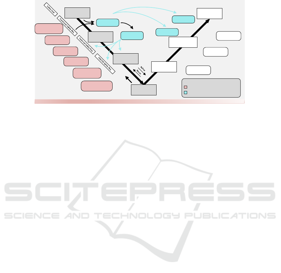
Figure 1 shows the overall structure of the ISO26262
based upon a V-model. It is a reference process model
for the different phases of product development. The
V-model describes the flow of the design process on
different level of abstraction, starting from item def-
inition, preliminary architectural assumptions, sys-
tem design, to hardware and software design. Each
level in the design flow interacts with the parent de-
sign. Parallel to the design flow, the ISO26262 defines
a requirements phase which also exists of different
subphases. There, the safety requirements (SR) e.g.
safety goals, functional SR, technical SR, hardware
and software SR are defined. Each requirements sub-
phase is derived from the parent requirements phase.
The design and requirements phases haven a very
tight interaction with each other, to support a high
traceability between design and requirements which
Automatic Testbench Generation for Simulation-based Verification of Safety-critical Systems in UML
71
SHARC
Item Definition
preAA
System Design
HW/SW Design
HW/SW Tests
System
Integration Tests
System Safety
Validation
Hazard and Risk
Analysis (ASIL)
Fault Tree
Analysis
Failure Mode and
Effect Analysis
HW/SW
Interface
HW Architectural
Metrics Evaluation
Reliability Analysis Methods with UML
Simulation-based Verification with UML
Early
Simulation
Testcases
Testcases
Testcase reuse
automatic
generate
test
Development/Design Verification/Validation
Design walk
through
Software in the
Loop
Hardware in
the Loop
Field tests
IP-XACT
functional,
non-functional
Testcases
Figure 1: Seamless integration of simulation-based evaluation in the ISO26262 design flow.
is demanded by the standard. Throughout the whole
design and requirements phase, the functional safety
standard demands different measures and methods to
evaluate the design depending on the ASIL level and
subphases. Popular examples of methods to support
the evaluation process are hazard and risk analysis,
FMEA, FTA, design walk trough and simulation, to
name only a few. The right side of the V-model ad-
dresses verification, testing and production where the
different sub phases like hardware, software and sys-
tem integration tests until system safety validation are
defined. It is also supported by various in-the-loop
processes like SIL, HIL and XIL.
4 METHODOLOGY
Since the design and development of safety-critical
systems is a cumbersome and costly task, it needs
novel methods to test evaluate the design in early
phases, during and throughout the whole development
process. Reusability of well-tested design, mech-
anisms or even whole safety concepts are experi-
encing a higher importance. Therefore we propose
simulation-based verification of UML/MARTE de-
sign models on preliminary Architectural assumption
(preAA) level with reusable components from our
System Component Library (SCL). This library in-
cludes all major components for a high level simu-
lation of systems from different domains e.g. auto-
motive, mobile computing, health care or multime-
dia. It also includes components in different ver-
sions and on different abstraction levels. These mod-
els serve on one hand as the starting-point for future
development and furthermore as verified and golden
reference for integration aspects. The properties of
the models are all taken from the standard defini-
tion for UML/MARTE system, hardware and soft-
ware models. In order to bring the components of
the SCL to live, they are linked to executable mod-
els in SystemC(-TLM) or SystemC-AMS. To speed
up the simulation time, the components provided by
our SCL are pre-compiled and implement an inter-
face to change all parameters at runtime or upon in-
stanciation. This has the advantage of being able to
parametrize or even reconfigure systems and com-
ponents without the need for recompiling the code
every time the system is simulated. Our methodol-
ogy to execute SystemC from UML/MARTE design
models is composed of four phases: Design-Phase,
Build-Phase, Connect-Phase and Run-Phase. More
detail on this methodology is given in (Weissnegger
et al., 2016) and (Weissnegger et al., 2015). Based
on the functional SRs from the functional safety con-
cept, defined as SysML models, and the information
from the preAA we are able to obtain further re-
quirements for the technical safety concept. Through
taking also non-functional properties (timing, power,
thermal) into account, we are able to refine the func-
tional SR and to define the technical SR. Furthermore
we are able to obtain inputs for our final system de-
sign, before costly implementation of faulty design.
Testbenches in the Universal Verification Methodol-
ogy (UVM), to test the design on preAA level through
simulation are automatically generated from the infor-
mation and constraints of the functional SR defined in
SysML. Furthermore constraint random verification
helps to cover all possible parameters and variants of
the system, but also to vary environmental conditions,
to find corner cases. These testbenches can be used
throughout the whole development cycle till the final
system integration and validation.
PEC 2016 - International Conference on Pervasive and Embedded Computing
72
4.1 UVM Testbench Generation from
SysML Requirements
We use a simple semi-formal language to define
our requirements as approaches such as (Kirchsteiger
et al., 2008) have shown that informal languages can
be too ambiguous for our application. The ISO26262
also agrees that informal languages should only be
used for applications with low ASIL levels such as A
and B and highly recommends to use semi-formal re-
quirements specifications for higher safety goals such
as C and D. Therefore we decided to use the bene-
fits of the UML profile SysML for the definition of
the requirements. As SysML for requirements lacks
in proper definition for safety, we defined an exten-
sion. Besides standard attributes id and text, follow-
ing attributes such as type ( functional SR, technical
SR, hardware SR, software SR), status (proposed, as-
sumed, accepted, reviewed), ASIL level, and pass/fail
have been added to the definition. Attributes such as
id, text, status and ASIL level are also recommended
by the ISO26262 standard. Each safety goal in our
approach is therefore clearly defined by our extension
for safety requirements.
The top level safety requirements (Safety Goals)
are derived from the hazard and risk analysis. These
safety goals lead to the definition of the functional
safety concept. Here the functional SR are derived
from the safety goals in conjunction with the preAA.
At least one functional SR shall be specified for
each safety goal, but also one functional SR can be
valid for several safety goals. Each functional SR is
described by the defined attributes in our extension
for safety requirements. Furthermore each functional
SR in our approach has several defined constraints
for functional and non-functional properties. These
constraints are defined in the MARTE value specifi-
cation language (VSL) and specify the boundaries for
a fail safe operation of the system. These constraint
precisely captures the original requirement and open-
ing up, through computer readable formalism, the
possibility of subsequent computer-aided analysis of
the characteristics of this design. The nfpConstraint
of MARTE are defined by arithmetic; logical or
time expressions formed by combining operators
such as (’<’,’≤’,’=’,’6=’,’≥’,’>’) but also ’and’, ’or’
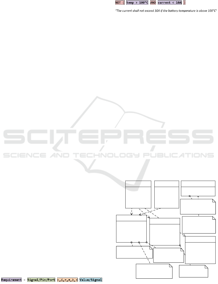
and ’xor’. An example of the definition of safety
requirements and constraints is given in Fig. 2.
The syntax used for our constraints follows the
following patterns:
Mutiple constraints can be connected via simple
Boolean statements such as:
In a next step the functional SR are derived from
the definition of the safety goals. An example for this
would be to reuse the battery pack from a prior de-
sign which has known operating conditions and test
if it is powerful enough to power the motor chosen
for the new design (using a preliminary specifications
provided by the manufacturer).
• The maximum operation temperature allowed for
the battery cells is 100
◦
C, therefore this tempera-
ture shall never be reached.
• Due to the choice of battery the maximum current
drawn from the cells shall not exceed 10A.
• The cell/module voltage shall remain between
2.5V (empty) and 4.25V (maximum charging
voltage)
• The state of charge for the individual cells shall
not be lower than 10% nor higher than 110% of
design capacity.
While textual or informal definition is easy to read,
according to ISO26262 a semi-formal notation for re-
quirements specifications is best qualified for ASIL
levels higher than B, shown in our requirements dia-
gram in Fig.2. After the systematic specification of
the functional SR and design of the preAA with the
help of our SCL, the technical SR can be derived.
To support the specification of the technical SR
and furthermore enable the verification in compliance
<<Constraint>>
{?}street_maneuver_lasvegas
{{VSL}load>(0,Nm) and load<(40,Nm)
and driver>(0,rpm) and
driver<(1000,rpm) and
env_cond>(20,C) and
env_cond<(50,rpm)}
id=1
type=SG
text= The battery shall
operate under safe
conditions
ASIL=C
status=assumed
pass_fail=false
<<SafetyRequirement>>
SR1
id=2
type=SG
text= The battery shall be
reliable
ASIL=B
status=assumed
pass_fail=false
<<SafetyRequirement>>
SR2
id=12
type=FSR
text= A BMS shall monitor &
control the battery and must
operate in working range
ASIL=B
status=assumed
pass_fail=false
<<SafetyRequirement>>
SR3
id=23
type=FSR
text= Watchdog shall cut Power
connection to battery in case of
too high temperature
ASIL=B
status=assumed
pass_fail=false
<<SafetyRequirement>>
SR4
<<nfpConstraint>>
{?} working_range_temp
{{VSL}temp>=(-20,C) and temp <=(60,C)}
kind=required
mode=mode1
<<nfpConstraint>>
{?} max_operating_temp1
{{VSL}temp<(150,C)}
kind=required
mode=mode1
<<nfpConstraint>>
{?} working_range_voltage
{{VSL}module_voltage>(15,V)
and module_voltage < (25.5,V)}
kind=required
mode=mode1
<<nfpConstraint>>
{?} working_range_current
{{VSL}i_bat<(300,A) and temp<(45,C)
and temp>(0,C)}
kind=required
mode=mode1
id=10
text= eVehicle shall drive specified
maneuver
<<Requirement>>
R1
<<Constraint>>
{?} street_maneuver_eu
{{VSL}load>(0,Nm) and load<(100,Nm)
and driver>(0,rpm) and
driver<(1000,rpm) and env_cond>(-
10,C) and env_cond<(35,rpm)}
id=32
type=FSR
text= If measured value exeeds
the working rage go to a safe
state in a given time
ASIL=B
status=assumed
pass_fail=false
<<SafetyReq uirement>>
SR5
Figure 2: Definition of safety and non-safety requirements
to derive automatically testbenches for verification.
Automatic Testbench Generation for Simulation-based Verification of Safety-critical Systems in UML
73

with the technical safety concept, we defined a novel
methodology to derive further requirements and in-
puts from the functional SR in coherence with the
early system design (preAA). Using the syntax for
safety requirements we are able to generate UVM ver-
ification components and whole testbenches from the
definition of the functional SR and their constraints.
For each constraint of the functional SR, a new UVM
validator is added on the ports or one end of the sig-
nal. A validator consists of a configurable comparator
with the pin/port/signal attached to one input and a
reference signal or constant value attached to the sec-
ond input. The output of the comparator can be either
1 (true) or 0 (zero) and are connected via arithmetic
or algebraic function blocks to create the boolean op-
erations. In addition we use non safety requirements
in the SysML specification to provide stimuli blocks
for relevant operating modes and driving maneuvers.
Depending on the non safety requirements and con-
straints and if the pin/port/signal is an unused input of
a block the testbench generator creates a stimuli block
and attaches it. This block generates either values
that are within the specifications in order to validate
proper operation or to generate invalid stimuli to ver-
ify safety mechanisms within the model. To vary the
parameters and stimuli of our system and to cover up
corner cases we use the benefits of Coverage-Driven
Verification (CDV), with its aim to detach from di-
rect - user depended - testing (Accellera, 2015). This
methodology provides the definition of so called ver-
ification goals, which can be verified by smart test
scenarios. The intelligence is mainly achieved by
creating simulation configurations (stimuli), with re-
spect to some predefined constraints. This concept
is widely known as Constraint Random Verification
(CRV) (Kitchen and Kuehlmann, 2007). CRV mainly
consists of two core concepts, which is on one hand
the usage of Markov-chain Monte Carlo to guarantee
coverage through probability and on the other hand
the processing of constraints with SAT solvers. As
described above, it is important to vary parameters
such that many different input combinations can be
covered. The defined internal values of the DUT vary
according to a predefined probability distribution. In
this case we use Gaussian distribution with the defini-
tion of a value of 3 sigma.
5 FUTURE WORK
To show the efficiency, this novel method will be
applied on a complex battery management system
example from the automotive industry. We will
show how the tesbenches are automatically gener-
ated from our defined requirements and constraint
in UML/MARTE. This testbenches will be automat-
ically connected to the design under test. Further-
more, SysML models will be used to define more pre-
cisely our stimuli inputs. In addition we will build
our methodology into the Eclipse Papyrus environ-
ment, so every UML editor will be able to simulate
UML/MARTE models by installing our plugin. This
tool will also be published for download and also be
used for educational purposes.
ACKNOWLEDGMENTS
The approach presented above is an experiment un-
dertaken in the framework of OpenES CATRENE
Project: CA703 - 2013 research program supported
by the FFG (Austrian Research Promotion Agency),
project-number 843380 in tight cooperation with
CISC Semiconductor.
REFERENCES
Accellera (2015). Universal Verification Methodology
(UVM) 1.2 User’s Guide. Technical report, Accellera.
Catrene (2016). OpenES CATRENE Project: CA703.
ETAS (2014). ETAS Embedded Systems Consulting: Elec-
tronic Control Unit ( ECU ) - Webinar Basics of Au-
tomotive ECU. pages 1–30.
ISO (2011). Functional Safety ISO26262 - Part 4: Product
development at the system level. 2011:1–35.
Kim, H., Wong, W. E., Debroy, V., and Bae, D. (2010).
Bridging the Gap between Fault Trees and UML State
Machine Diagrams for Safety Analysis. 2010 Asia
Pacific Software Engineering Conference, pages 196–
205.
Kirchsteiger, C. M., Grinschgl, J., Trummer, C., Steger, C.,
Weiß, R., and Pistauer, M. (2008). Automatic test gen-
eration from semi-formal specifications for functional
verification of system-on-chip designs. 2008 IEEE In-
ternational Systems Conference Proceedings, SysCon
2008, pages 421–428.
Kitchen, N. and Kuehlmann, A. (2007). Stimulus Genera-
tion for Constrained Random Simulation. In Proceed-
ings of the 2007 IEEE/ACM International Conference
on Computer- aided Design, pages 258–265, Piscat-
away, NJ, USA.
Mader, R., Armengaud, E., Leitner, A., Kreiner, C.,
Bourrouilh, Q., Grießnig, G., Steger, C., and Weiß,
R. (2011). Computer Safety, Reliability, and Se-
curity: 30th International Conference,SAFECOMP
2011, Naples, Italy, September 19-22, 2011. Proceed-
ings. chapter Computer-A, pages 113–127. Springer
Berlin Heidelberg, Berlin, Heidelberg.
Mhenni, F. and Nguyen, N. (2014). Automatic Fault
Tree Generation From SysML System Models. 2014
PEC 2016 - International Conference on Pervasive and Embedded Computing
74

IEEE/ASME International Conference on Advanced
Intelligent Mechatronics (AIM), Besancon, France.
OMG (2016). UML Profile for MARTE: Modeling and
Analysis of Real-Time Embedded Systems. Techni-
cal report, Object Management Group.
Weissnegger, R., Kreiner, C., Pistauer, M., R
¨
omer, K.,
and Steger, C. (2015). A Novel Design Method
for Automotive Safety-Critical Systems based on
UML/MARTE. In Proceedings of the 2015 Forum
on specification & Design Languages, pages 177–184,
Barcelona, Spain.
Weissnegger, R., Schuss, M., Kreiner, C., Pistauer, M.,
R
¨
omer, K., and Steger, C. (2016). Simulation-based
Verification of Automotive Safety-critical Systems
Based on EAST-ADL. Procedia Computer Science,
83:245–252.
Automatic Testbench Generation for Simulation-based Verification of Safety-critical Systems in UML
75
