
The Temperature Control System of Continuous Diffusion Furnace
Xianxin Ke, Zhitong Luo, Yujiao Zhu and Yang Liu
Department of Mechanical and Electrical Engineering, Shanghai University, No. 149, Yanchang Road, Shanghai, China
Keywords: Continuous Diffusion Furnace, P-N Junction, Smith Estimating Pre-Compensation, Temperature Control
System.
Abstract: The diffusion furnace is an important and indispensable equipment in the production process of solar cell,
it plays a crucial role in the photoelectric conversion efficiency of the solar cell. Production efficiency and
temperature control precision of traditional closed diffusion furnace is low. To solve this problem,this
paper presents a temperature control system of continuous diffusion furnace. The system uses PID cascade
control algorithm based on Smith estimating pre-compensation to achieve the temperature control of furnace
and ensure the uniformity and stability of the temperature, so as to ensure the uniformity of the dopant
diffusion. The simulation results verify the effectiveness of the control algorithm; and practical experiments
prove the feasibility of the temperature control system.
1 INTRODUCTION
Solar panel as the core part of the solar photovoltaic
power generation (Cao et al., 2013), it can convert
the solar energy into electric energy stored in
batteries and promote the work load. In the whole
production process of solar cells, P-N junction
process (Wang et al., 2012) is a crucial step, it is
related to the conversion efficiency of crystalline
silicon solar cells and the precision and stability of
the process temperature control directly affects the
quality of P-N junction. So the diffusion furnace is
indispensable important equipment in solar cell
production process, the temperature control accuracy
and the stability of the system are very important.
According to the requirements of the automatic
control temperature, PID control, cascade control
(Gervini and Perondi, 2014), Smith estimating pre-
compensation (Ma et al., 2014) and compound
control among them have gradually replaced the
traditional PID control. At present, temperature
control technology of diffusion furnace equipment in
some foreign companies is more advanced, such as
Germany’s BTU (Anonymous, 2008), the United
States’ CENTROTHERM (Yan et al., 2012) and so
on. In recent years, the domestic diffusion furnace
equipment develops quickly in upgrading and
technology, but compared with the international
advanced diffusion furnace equipment, there is still
gap.
Diffusion furnace mostly adopts the method of
resistance heating to heating; the temperature control
system contains one order inertial link with pure
hysteresis. The link has characteristics with big
inertia, pure lag and nonlinear, and it is difficult to
use mathematical method to establish model and
determine the parameters. And now the temperature
control precision requirement of diffusion furnace is
higher, the traditional furnace temperature control
system cannot meet the requirements. This paper
designs a continuous diffusion furnace that uses PID
cascade control algorithm based on Smith estimating
pre-compensation to guarantee the uniformity and
stability of the temperature, so as to ensure the
uniformity of the dopant diffusion, and to improve
photoelectric conversion efficiency of silicon (Olsen
2012).
2 DESIGN OF CONTINUOUS
DIFFUSION FURNACE
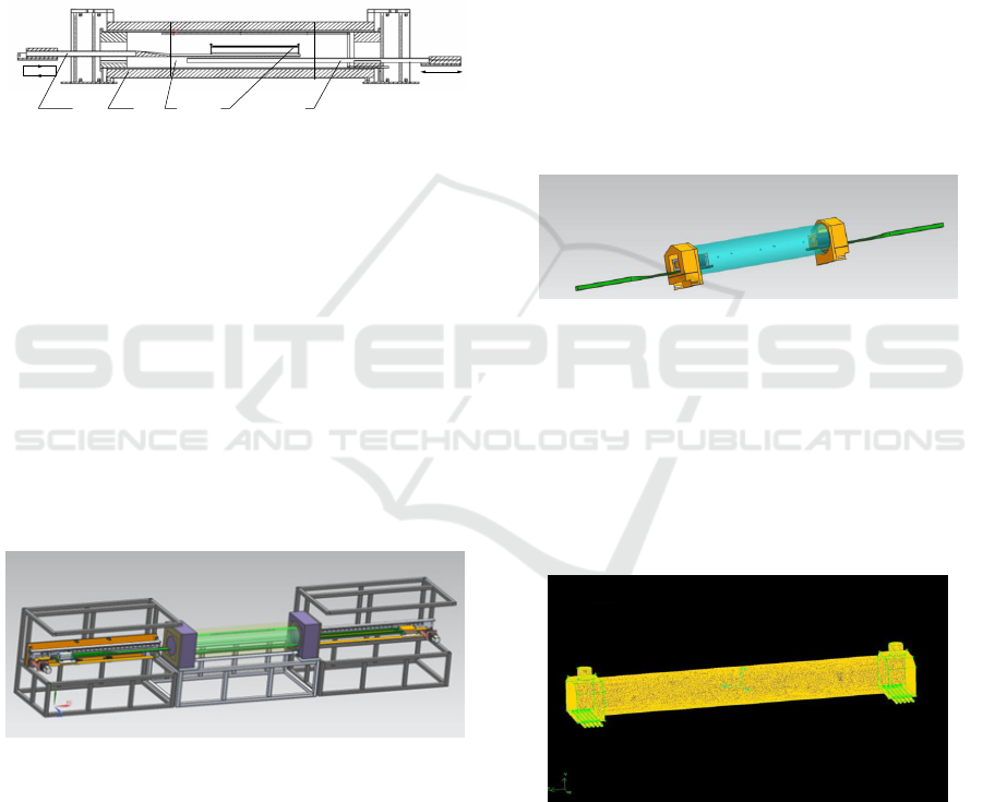
As shown in Figure 1 is diffusion process of
continuous diffusion furnace, it is divided into two
steps:
1) Quartz boat 4 carrying silicon wafers is put
on the left paddle 1 and loaded into furnace tube 2 of
diffusion furnace from left. Right paddle 5 goes into
furnace tube 2 from the right and stop go forward
when it arrives constant temperature area 3. Left
Ke, X., Luo, Z., Zhu, Y. and Liu, Y.
The Temperature Control System of Continuous Diffusion Furnace.
DOI: 10.5220/0005996402270233
In Proceedings of the 13th International Conference on Informatics in Control, Automation and Robotics (ICINCO 2016) - Volume 1, pages 227-233
ISBN: 978-989-758-198-4
Copyright
c
2016 by SCITEPRESS – Science and Technology Publications, Lda. All rights reserved
227
paddles 1 stop go forward when quartz boat arrives
at central region of constant temperature area 3.
2) The left paddle 1 failing by elevating
mechanism and handover quartz boat on it to right
paddle 5. Then left paddle 1 exits form furnace tube
2 and rises to the original position to reload the
silicon wafer. And right paddle 5 exits slowly from
constant temperature area 3, when the left side
silicon wafer on the quartz boat 4 exits from the
constant temperature area 3, the right paddle 5 exits
from diffusion furnace tube 2 and waiting to unload
the quartz boat 4.
Figure 1: Diffusion process of continuous diffusion
furnace.
Where 1-Left paddle
2- Furnace tube
3- Constant temperature area
4- Quartz boat
5- Right paddle
According to working process, the mechanical
structure design of the equipment is shown in Figure
2. The overall system of the continuous diffusion
furnace comprises 5 parts: a purification cabinet, a
gas source cabinet, a control cabinet, a resistance
heating furnace cabinet and a transfer system. The
equipment profile dimension is about 7480 (mm) *
1200 (mm) * 1500 (mm).
Figure 2: The mechanical structure of continuous diffusion
furnace.
3 TEMPERATURE UNIFORMITY
ANALYSIS OF CONTINUOUS
DIFFUSION FURNACE
In order to design temperature control system,
determine distribution ways of heating furnace wire
and whether need air curtain in the ends of furnace
tube, we need further analyze temperature
distribution of the diffusion furnace. The FLUENT
is used to modeling and simulation, the numerical
simulation analysis for the furnace temperature of
continuous diffusion furnace to get a better
temperature control method.
3.1 Establish Geometric Model of the
Continuous Diffusion Furnace
In this paper, we mainly study the temperature
distribution of continuous diffusion furnace, so
select reaction chamber of the diffusion furnace as
the research object. The geometric model of
continuous diffusion furnace as shown in Figure 3, it
mainly consists a feeding mechanism, the furnace
cavity, air curtain device, windpipe etc. And there
are three airway distributed in same angle along the
axial direction of diffusion furnace.
Figure 3: Geometric model of the continuous diffusion
furnace.
Grid division is the first step, the areas of the
oven cavity and furnace door all using tetrahedral
meshes, the Tet/Hybird grid type and internal grid
size is 10mm, as shown in Figure 7. The equations
of the model are solved by using the continuous
equation, momentum equation and energy
conservation equation.
Figure 4: Grid division of the continuous diffusion
furnace.
3.2 Set Physical Parameters and
Boundary Conditions
There are two types of heat exchange between the
inner wall of the furnace tube and the air inside the
furnace tube: one is the heat convection between
1 2 3 4 5
ICINCO 2016 - 13th International Conference on Informatics in Control, Automation and Robotics
228
each other; another is heat transfer by radiation from
inner wall of furnace tube to air inside furnace tube.
Thus , according to the actual situation of the
continuous diffusion furnace, the boundary
conditions and physical parameters are adopted as
follows:
1) Set outer wall of the continuous diffusion
furnace as coupled wall; Set inner wall surface as
convection heat transfer and radiation wall; Set
Internal and external wall material as silicon dioxide.
2) Set temperature of furnace mouth without air
curtain as 730K.
3) Set air intake velocity of air curtain as 1m/s,
temperature is 730K; the relative pressure of outlet
surface is 0Pa;
4) Air density is 1.225K/ m3, the coefficient of
viscosity is 1.789×e-0.5kg/m·s, the coefficient of
thermal conductivity is 0.1242W/m·k, the specific
heat of air is 1006.43J/kg·K.
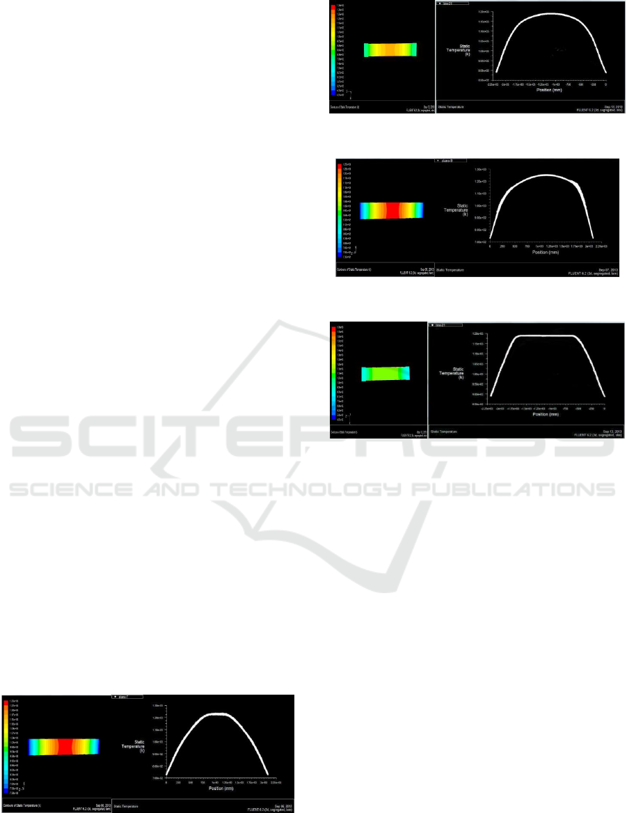
3.3 Analysis of Numerical Simulation
Results of Temperature Field
In order to realize better distribution of temperature
field in furnace cavity of continuous diffusion
furnace, conditions that furnace mouth without air
curtain or with air curtain are compared respectively
by 3-zone heating and 5-zone heating. The
temperature distribution in the furnace is simulated
by using the FLUENT to simulate the three-
dimensional temperature of the geometry model, as
shown in figure 5.
In Figure 5, (a) is temperature simulation result
of continuous diffusion furnace without air curtain
and heated by 3-zone hennaing; (b) is temperature
simulation result of continuous diffusion furnace
with air curtain and heated by 3-zone hennaing; (c)
is temperature simulation result of continuous
diffusion furnace without air curtain and heated by
5-zone hennaing; (d) is temperature simulation result
of continuous diffusion furnace with air curtain and
heated by 5-zone hennaing.
(a) Temperature simulation result of continuous diffusion
furnace without air curtain and heated by 3-zone hennaing
(b) Temperature simulation result of continuous diffusion
furnace with air curtain and heated by 3-zone hennaing
(c) Temperature simulation result of continuous diffusion
furnace without air curtain and heated by 5-zone hennaing
(d) Temperature simulation result of continuous diffusion
furnace with air curtain and heated by 5-zone hennaing
Figure 5: Temperature simulation results of continuous
diffusion furnace in different conditions.
From the figure (a) and figure (b) we can see that
when diffusion furnace is heated by 3-zone
hennaing, if there is no air curtain, the temperature
change in the furnace chamber like a parabola,
which cannot meet basic requirement of diffusion; if
adding air curtain, the relative temperature
difference of the middle area of about 1m in the
furnace chamber is small but not constant, so it
cannot meet the basic needs of the diffusion. From
the figure (c) and figure (d) we can see that when it
is heated by 5-zone hennaing, if there is no air
curtain, temperature difference exists in the middle
area of about 1m in the furnace chamber is small but
not constant, this situation cannot meet the basic
needs of the diffusion; When adding air curtain at
furnace mouth, the temperature of the middle area of
about 1m in the furnace chamber is constant, so this
case can meet basic needs of the diffusion.
The Temperature Control System of Continuous Diffusion Furnace
229

4 TEMPERATURE CONTROL
ALGORITHM DESIGN
The traditional PID control system can satisfy
requirements of the system in most of cases because
of its advantages that performance mature, easy to
implement, eliminate the static error of advantages
in most cases performance; but in process that
control nonlinear, time variable, coupling and
complex structure parameters, its effect is not very
good. For this problem, this paper presents a PID
cascade temperature control system based on Smith
estimating pre-compensation compensation, the
system can form cascade control by monitoring
temperature of the furnace chamber and the furnace
wall at the same time to meet performance
requirements with small temperature overshoot,
soon stabilization, high control precision.
4.1 Algorithm Design of the Control
System
The purpose that design high precision temperature
control system of diffusion furnace is mainly to
ensure diffusion uniformity of the phosphorus
element to silicon wafer. At present, main problems
of the temperature control system of diffusion
furnace is time of heat transfer process is too long
from furnace wall to furnace chamber, for which we
design a PID cascade control algorithm based on
Smith estimating pre-compensation. Thought of
Smith predictor is that regulated variable delayed is
responded to controller in advance. Thought of
cascade control is that adding a new control object -
furnace wall temperature based on the original
control object -furnace chamber temperature, it
could response interference in advance; and increase
the furnace wall temperature control can improve the
quality of the whole control system. Cascade control
system with Smith estimating pre-compensation as
shown in Figure 6.
Figure 6: Transfer function schematic of cascade control
system with Smith estimating pre-compensation.
In figure 6, Gc1(s) and Gc2(s) denote
respectively the transfer functions of principal and
subordinary regulators. Gv(s) denotes the transfer
function of actuator; Go2 (s) denotes the transfer
function of subloop controlled object; Go1(s)e-τs
denotes the transfer function of t main loop
controlled object; Gm1(s) and Gm2(s) denote
respectively the transfer functions of main and
auxiliary transmitter; Gv(s) denotes the transfer
function of actuator; Go(s)(1-e-τs) is the Smith
predictor of main loop.
In the Smith predictor:
(s)
o
(s)G
v
(s)G
c
(s)G
m
G
(s)
o
(s)G
v
(s)G
c
(s)G
o
(s)G
m
G
o
G
2211
2211
(s)
+
=
(1)
The equivalent transfer function of the subloop
is:
)()()()(
)()()(
)(
)(
)(
s
v
Gs
o
Gs
c
Gs
m
G
s
o
Gs
v
Gs
c
G
sR
sY
s
o
G
2221
22
2
2
2
+
==
′
(2)
So, transfer function of cascade control system
with Smith estimating pre-compensation is:
s
e
s
m
Gs
o
Gs
o
Gs
o
G
s
o
Gs
o
Gs
o
G
sR
sY
sG
τ
−
′
+
′
==
)(1)(1)(
2
)(1
)(1)(
2
)(
)(
1
)(
)(
(3)
The characteristic equation of the system can be
seen from the above formula:
01
12
1 =
′
+ )()()()(
s
m
Gs
o
Gs
o
Gs
o
G
(4)
The characteristic equation does not contain e
-τs
,
so Smith predictor can make the temperature
hysteresis quality does not affect the system.
4.2 System Simulation and Result
Analysis
In this paper, the Simulink module of Matlab
software is used to simulate the system control
algorithm. In order to verify the control effect of
cascade control method with Smith estimating pre-
compensation, the conventional PID cascade control
system is compared with it. The simulation model of
the PID cascade control system with Smith
estimating pre-compensation and the conventional
PID cascade control system as shown in Figure 7.
The output response curve of the system under
normal circumstances without interference as shown
in Figure 8.
In the case of adding interference, for example,
adding interference signal in the subloop when
system stability time is 7000s. Set interference
signal is the step signal, the output response curve of
system as shown in figure 9.
Gc1(s)
Gc2(s) Gv(s)
Go2(s)
Go1(s)e
-τs
Go(s)(1-e
-τs
)
Gm2(s)
Gm1(s)
N2(s) N1(s)
ICINCO 2016 - 13th International Conference on Informatics in Control, Automation and Robotics
230
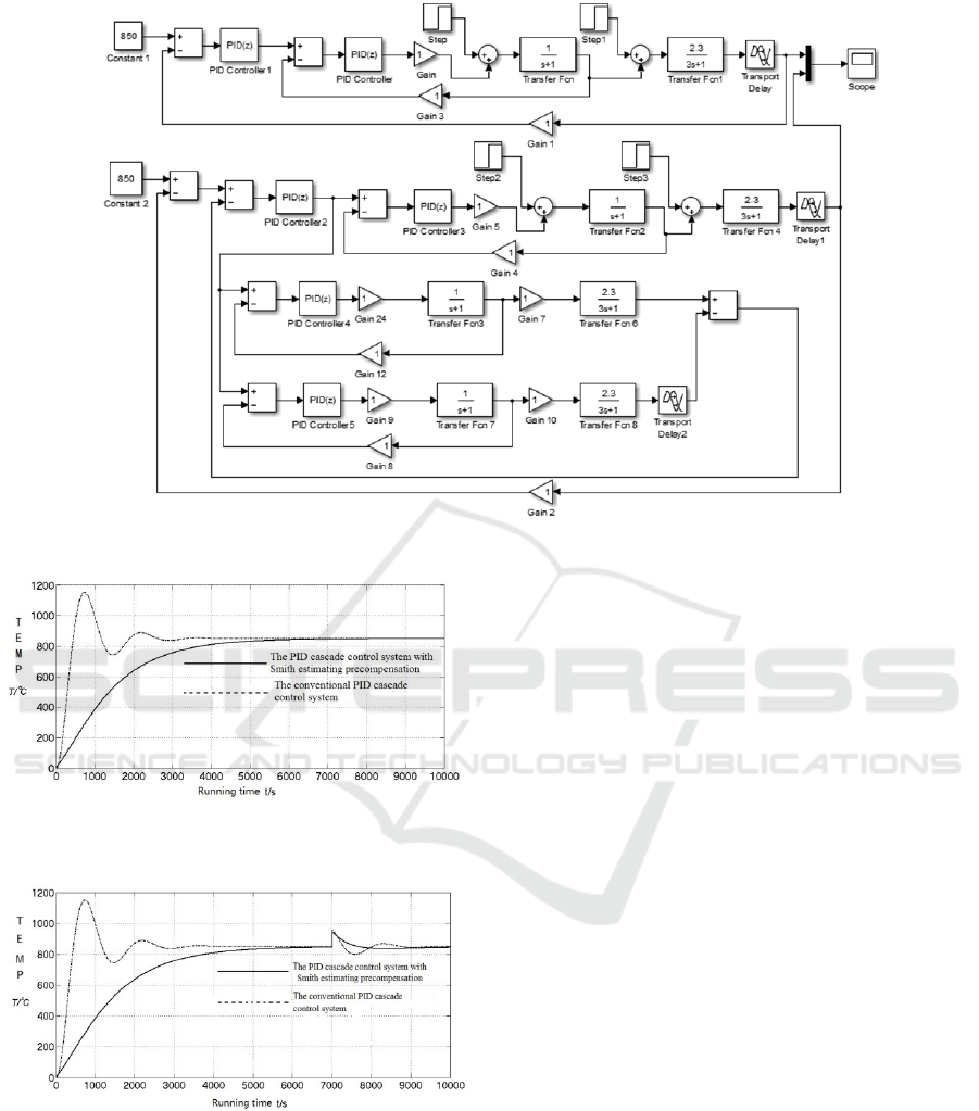
Figure 7: The simulation model of the PID cascade control system with Smith estimating pre-compensation.
Figure 8: Output response curve of the system under
normal circumstances.
Figure 9: Output response curve of the system under
adding interference.
As can be seen from figure 8, compared with the
conventional PID cascade control system, the PID
cascade control system with Smith predictor is more
stable and no overshoots, thus it can protect the
diffusion furnace and the control effect is better.
As can be seen from Figure 9, the PID cascade
control system with Smith predictor is better in anti-
interference ability than the conventional PID
cascade control system.
To sum up we know, no matter in normal
circumstances, or in the case of interference, the PID
cascade control system with Smith estimating pre-
compensation is better than the conventional PID
cascade control system in control precision, stability
and anti-interference ability.
5 EXPERIMENT
5.1 Temperature Control System
Design of Continuous Diffusion
Furnace
As shown in Figure 10, temperature control system
is composed with temperature cascade control
system and temperature overtemperature protection
system. The principle of temperature cascade control
system is that use subloop composed of the furnace
wall outer thermocouple (A', B', C', D', E'),
thermostat 2, trigger circuit, and power elements to
control the heating current of furnace wire. And
thermocouple (A, B, C, D, E) in the furnace chamber
will measure temperature and compared with setting
value, then together with thermostat 1, thermostat 2,
triggering circuit and power elements compose main
The Temperature Control System of Continuous Diffusion Furnace
231
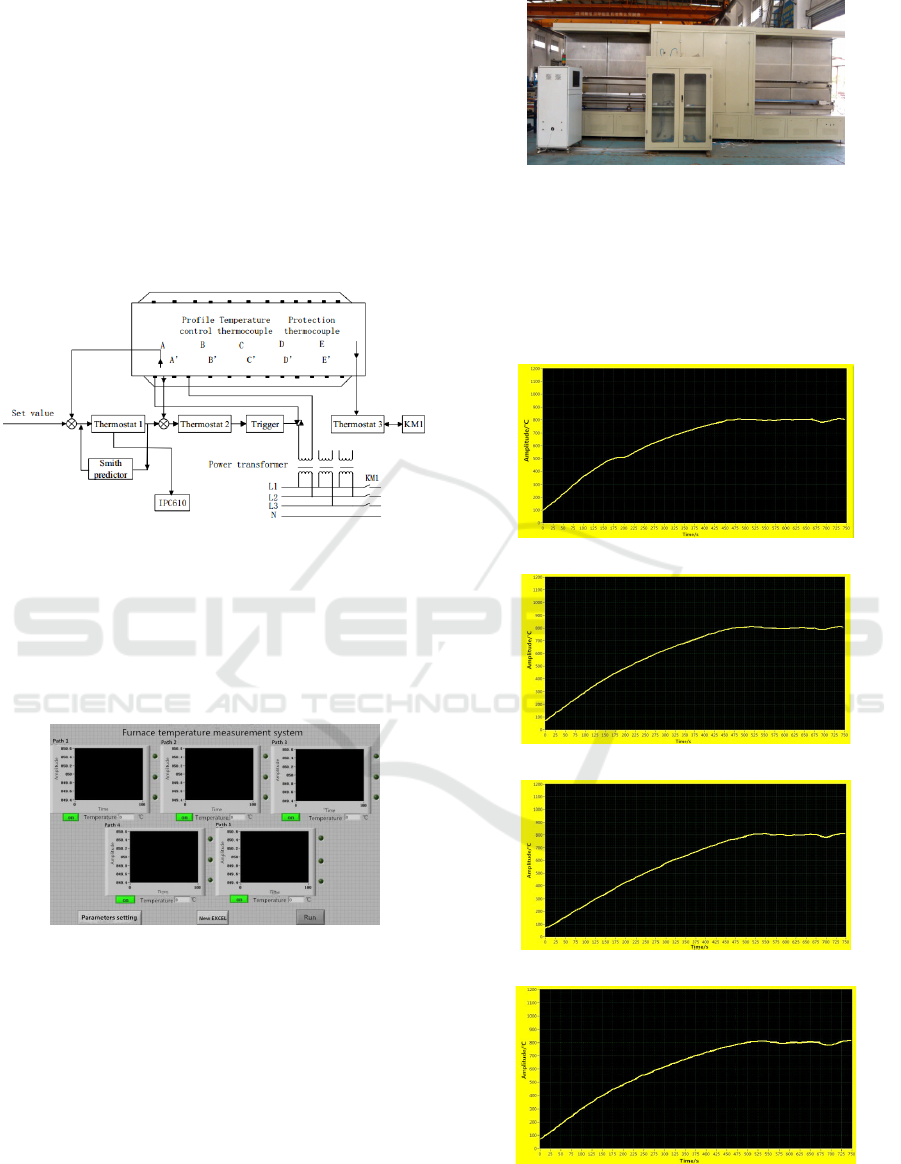
circuit to monitor furnace temperature of constant
temperature area. The principle of overtemperature
protection system is that overtemperature protection
thermocouple, thermostat 3 (PLC), contactor KM1
compose control system, when the furnace
temperature is higher than the maximum
temperature that equipment can withstand in long
time, the PLC (thermostat 3) output signal to make
contactor KM1 power failure, and to stop heating
furnace wire, at the same time PLC (thermostat 3)
output signal to alarm indicator lamp to
produce sound-light alarm.
Figure 10: Temperature control system of Continuous
diffusion furnace.
The interface of temperature control system is
written by LabVIEW software, as shown in figure
11. The upper computer interface mainly composes
display of real-time temperature, settings of
parameters, establishment of the EXCEL table, etc.
Figure 11: The interface of temperature control system.
5.2 Experimental Result Analysis of
Continuous Diffusion Furnace
The prototype of the continuous diffusion furnace
used in the experiment as shown in Figure 12, which
including the control cabinet, gas source cabinet,
purification cabinet, resistance heating furnace
cabinet and so on.
Figure 12: The prototype of the continuous diffusion
furnace.
Using the LabVIEW record data of continuous
diffusion furnace in heating process, as shown in
Figure 13, (a), (b), (c), (d), (e) denote respectively
the temperature heating curves of point A, B, C, D,
E in figure 13.
(a) The temperature heating curve of point A
(b) The temperature heating curve of point B
(c) The temperature heating curve of point C
(d) The temperature heating curve of point D
Figure 13: The actual furnace temperature curves of
different position.
ICINCO 2016 - 13th International Conference on Informatics in Control, Automation and Robotics
232

(e) The temperature heating curve of point E
Figure 13 (cont.): The actual furnace temperature curves
of different position.
From the above temperature curves can be seen
that heating process is roughly same in point A and
point E, point B and D but there exists some
difference among point A, B, C, D, E during
heating process. The reasons that cause difference of
temperature curves between A, E and B, C, D may
be due to the influence of the air curtain at the
furnace mouth, or caused duo to during heating
process, first heating temperature to 500℃and then
heating temperature 800℃. There is fluctuate after
temperature stable at 800 ℃ , the season is that
paddle enter in furnace from the furnace door cause
air fluctuation and then cause temperature
fluctuation.
Compared temperature simulation curve of
system shown in figure 9 with the actual temperature
heating curves shown in figure 13, we can know that
the heating rate and time that reach to stable
temperature both are roughly same. In the case of
external interference, the system can restore to a
stable state effectively.
6 CONCLUSIONS
In this paper, the temperature of continuous
diffusion furnace is the research object. Aim at the
temperature control characteristics of diffusion
furnace with large inertia and pure hysteresis, this
paper proposes a furnace temperature control system
with PID cascade control algorithm based on Smith
prediction compensation. Through the simulation
analysis and actual experiments of furnace
temperature control system, the paper verifies the
effectiveness of the control algorithm and the
effectiveness of the furnace temperature control
system.
ACKNOWLEDGEMENTS
This research is supported by National Key
Scientific Instrument and Equipment Development
Projects of China (2012YQ150087), National
Natural Science Foundation of China (61273325).
REFERENCES
Cao, S. G., Zheng, W. H., Xiao, L. 2013. Development
status and development trend of diffusion equipment,
Machinery, Vol. 585, pp.69-71.
Wang, R., Wu, X. M., Xu, Z., Yuan, J. B., Sun, Y. Z., Yi,
S. 2012. Electrical properties of strained Si p-n
junctions, 2012 IEEE 11th International Conference
on Solid-State and Integrated Circuit Technology
(ICSICT-2012). Beijing China, pp.1079-1081.
GERVINI, Victor Trigon, PERONDI, Eduardo André.
2014. Cascade Control of a Pneumatic Servo
Positioning System using Neural Networks, 2014 2nd
International Conference on Manufacturing
Engineering and Technology for Manufacturing
Growth (METMG 2014). USA, Vol. 902, pp. 225-230.
Ma, G. Y., Jia, J. R, Bo, J. Q. 2014. The design of a
controller with Smith predictor for networked control
systems with long time delay, 2014 IMSS
International Conference on Future Mechatronics and
Automation (ICMA 2014 V1), Beijing China, vol. 909,
PP.317-322.
Anonymous. 2008. Cimetrix provides connectivity
solution to centrotherm for semiconductor & solar cell
manufacturing, Electronics Business Journal.
Yan, X. W., Zhang, J. G., Deng, B., Yuan, Y. H., Pan, X.
C., Yang, Y. B. 2012. Application and Development
Trend of the LTCC Sintering Furnaces, Equipment for
Electronic Products Manufacturing, vol. 2, PP.1-4.
Olsen, T. 2012. Key Considerations for Selection of
Diffusion Furnaces, 2012 19th Biennial
University/Government/Industry, Micro/Nano
Symposium (UGIM), Berkeley, CA, 2012: 1.
CHEN, S. D., ZHANG, Y., WANG, J., ZHAO, H. 2013.
Connection between heat diffusion and heat
conduction in one-dimensional system, Xiamen
University.
Song, Y. M., Bin, Y. 2012. Predictive Functional Cascade
Temperature Control for Bench-Scale Batch Reactor,
The 31st Chinese Control Conference (CCC), Hefei
China, pp.4079-4084.
Lai, Chien-Liang, Hsu, Pau-Lo. 2010. Design the remote
control system with the time-delay estimator and the
adaptive smith predictor, IEEE, vol.1, pp.73-80.
Xu, G., Lin, Y. S., Hu, T. S., Chen, L. 2013. Application
of virtual instrument technology in temperature
acquisition system, Journal of Wuhan Institute of
Technology, vol. 7, pp.81-86.
The Temperature Control System of Continuous Diffusion Furnace
233
