Development of Self Support Device and Control for Operating the
Wheelchair for Upper Limb Disabled Persons
Taku Itami
1
, Toshihito Yabunaka
1
, Ken’ichi Yano
1
, Yasuyuki Kobayashi
2
,
Takaaki Aoki
3
and Yutaka Nishimoto
4
1
Dept. of Mechanical Engineering, Mie University, 1577 Kurimamachiya-cho, Tsu City, 514-8507, Japan
2
LUMINOUS JAPAN CO., LTD., 68 Hagae, Murakami, 959-3134, Japan
3
Dept. of Rehabilitation and Orthopedics, Gifu University Hospital, 1-1 Yanagido, Gifu, 501-1193, Japan
4
Dept. of Surgical Nursing, Gifu University School of Medicine, 1-1 Yanagido, Gifu, 501-1193, Japan
Keywords:
Exoskeleton, Rehabilitation, Operating Analysis, Electromyographic(EMG) Signals.
Abstract:
Nowadays, it has been actively expanded to develop assist robots attached directly. In this study, we focused
on developing an exoskeletal robot, specifically, a force transmission robot with a rotary drive type ratchet
mechanism, to enable users with upper limb disability to make use of their residual function to achieve better
function of their upper limbs. A lock/unlock mechanism on the elbow joint is effectively used to transmit the
user’s residual function around the shoulder to the hand. We conducted verification experiments on whether the
developed mechanism enables the user to transfer the remaining force in the shoulder joint to operation force
in the hand. Three subjects with C5 and C6 spinal cord injury with disabilities affecting their hands, lower
limbs, and trunk muscles performed the verification experiment with the developed device. We confirmed that
they could operate a wheelchair on a slope and on grass when using the developed device, and they could use
their residual function around the shoulder more strongly. It can be expected to rehabilitation effect.
1 INTRODUCTION
The number of disabled people who have lost body
function due to accident or illness has recently been
increasing. Injuries sustained in a road or sports acci-
dent where damage to the cervical cord means the per-
son cannot feel pain or temperature, and cannot move
their upper limbs and lower limbs in many cases.
These injuries are one of the main factors why peo-
ple need to use a wheelchair in daily life. There are
over 100,000 people with spinal cord injury, and it is
estimated that more than 5,000 people newly suffer
such injury every year.
In recent years, there has been consider-
able research on exoskeletal robots that substi-
tute for users’ the loss of function or amplify
their power (Tsukahara et al., 2015),(M. H. Rah-
man and Archambault, 2015),(Juanjuan Zhang,
2015),(Mao et al., 2015),(Hsieh et al., 2015),
and we have also developed upper limb mo-
tion support robots(N.Mizutani and Y.Kobayashi,
2013),(T.Watanabe et al., 2011),(T.Yabunaka et al.,
2014).
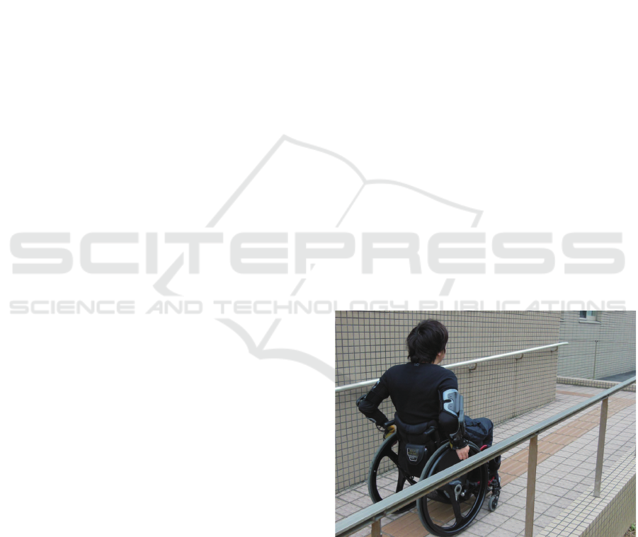
However, the power assist exoskeletal robots de-
Figure 1: Motion assist robot for the upper limbs.
veloped in previous studies have required a high-
power drive system because the robots support move-
ment directly by using motors and other mechanisms.
This has meant that people with cervical cord in-
jury are not able to make use of their residual func-
tion because their limbs are moved by external power
sources. This also introduces many device problems
such as increased weight due to using a battery and
466
Itami, T., Yabunaka, T., Yano, K., Kobayashi, Y., Aoki, T. and Nishimoto, Y.
Development of Self Support Device and Control for Operating the Wheelchair for Upper Limb Disabled Persons.
DOI: 10.5220/0005990404660471
In Proceedings of the 13th Inter national Conference on Informatics in Control, Automation and Robotics (ICINCO 2016) - Volume 2, pages 466-471
ISBN: 978-989-758-198-4
Copyright
c
2016 by SCITEPRESS – Science and Technology Publications, Lda. All rights reserved
large motor, reduced portability, and limits on the du-
ration of continuous use. These problems reduce the
utility, and there are also concerns over the loss of
residual function resulting from support by an exter-
nal power source.
We are therefore focusing our present work on the
residual function of the upper limbs in people who
use manual wheelchairs. We aim to develop a robot
orthosis that can make use of their residual function.
In cases of paralysis due to stroke or cervical cord
injury, the paralysis has a great effect on terminal
nerves. However, muscles which are nearer to the
trunk often experience milder symptoms. In partic-
ular, although people might not be able to exert force
because they have strong paralysis of the hands and
forearms. However, the area within the shoulder cir-
cumference on the trunk is often not paralyzed and
has muscles to exert force. There are many relatively
large muscles within the shoulder circumference, and
large movements can be achieved by using them. If
people can utilize these muscles as an assist source,
the robot orthosis is able to support the movement
based on their intention. The robot does not require a
high-power drive system as used in previous studies.
The robot orthosis is able to provide support by using
only a drive system with the minimum requirements
for transmitting residual function to help operate the
hand.
2 UPPER LIMB DYSFUNCTION
The Modified Zancolli classification is usually used
to evaluate upper limb function in people with cervi-
cal spinal cord injury. According to this system, the
C5 classification indicates the person can operate a
manual wheelchair, C4 or lower injury indicates the
need to use an electric wheelchair as they have little
residual function, and C5 or C6 indicates the bound-
ary between using a manual wheelchair and an elec-
tric wheelchair.
First, we measured the remaining power in the
shoulder joint circumference and the elbow joint cir-
cumference of a person with cervical cord injury. The
subject was a man with modified Zancolli classifica-
tion of C6B1 in his right arm and C5B in his left arm.
In this experiment, we measured the extension and
flexion power of his shoulder and elbow joints five
times each using a push-pull gauge, and calculated
the joint torque by taking the average. Table 1 shows
the experimental results.
In the experimental results, the extension torque
of the elbow joint could not be measured. In other
words, the former power of the elbow to extend was
fully lost.
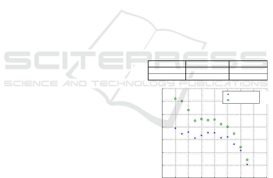
As the next step, we measured the tangential op-
erating force on the wheel rim of the wheelchair com-
paring 1 link of the elbow joint (Subject’s elbow is
locked at 90[deg].) and 2 link of the elbow joint (Sub-
ject can operate the wheelchair freely.) by using the
Push-pull gauge. We experimented that the subject’s
hand position started from 140[deg] of the wheelchair
backward to 30[deg] of the wheelchair forward by
10[deg]. The experiment was performed twice for
each hand position, and calculated the average value
as the operating force. Fig 2 shows the results of
the experiment. As the result, the subject whose el-
bow joint is locked can put power to the wheel rim of
the wheel chair to operate in the entire operation area
compared to 2 link of the elbow joint. In particular,
a meaningful difference was seen in initial operation
interval. This result is thought that the power of the
shoulder can translate to the hand directly by locking
the elbow joint. In other words, the subject can add
torques to operate on such steps with high resistance.
We also confirmed that the power loss in the elbow
joint had a large influence during wheelchair opera-
tion.
Table 1: Residual torque at the shoulder and elbow joints
for modified Zancolli classification of C6B1.
Subject Extension torque Flexion torque
Shoulder joint 8.6[Nm] 11.3[Nm]
Elbow joint 0.0[Nm] 20.3[Nm]
b
b
2 link model
1 link model
020406080100120140160
0
10
20
30
40
50
60
70
Contact angle of hand and wheel rim [deg]
Tangential direction force [N]
Figure 2: Measured results of operation force between 2
link and 1link.
3 DEVELOPED ROBOT
ORTHOSIS
The lock mechanism in the elbow joint is created by
Development of Self Support Device and Control for Operating the Wheelchair for Upper Limb Disabled Persons
467
using a static element such as an orthosis and a free
mechanism depending on the situation by using a
drive system. The developed robot orthosis is in-
tended to support the independence of disabled people
in everyday life. Therefore it is desirable for the or-
thosis to be light, compact, and inexpensive. It is also
desirable for it to offer long-term use and durability.
We use a ratchet mechanism that is able to withstand
the load of the lock mechanism and that has flexibility
in the rotational direction. We use the small-size DC
motor to drive the component, and we control these
parts to lock or unlock in a timely fashion. Figure
1 shows the robot orthosis that transfers the residual
function from the shoulder joint circumference to the
hands.
Our device consists of a drive mechanism, bat-
tery, control board in one part, and this device has
the special orthosis, and the glove sensor attached
to the hand that can detect contact to the rim of the
wheelchair. Our robot orthosis can be programmed
to drive independently. The sensors used are a small
rotary encoder for detecting the elbow joint, a glove
sensor for detecting contact with the wheel rim of
the wheelchair, a photo interrupter for controlling the
motor. When people with a cervical cord injury op-
erate a wheelchair, they operate it by pushing their
hand on the rim because they are unable to grasp the
rim. We therefore use a force sensor to detect contact
with the rim. In terms of the orthosis, we developed
a special orthosis by using two types of materials to
transfer power from the muscles within the shoulder
to their hands. This orthosis can provide legged robot-
enhancing capability, and also provides pronation and
supination to the forearm.
3.1 Rotary Drive Type Ratchet
Mechanism And Control
We developed a component that employs a ratchet
mechanism which has an externally toothed gear and
an internally toothed gear in one part. Two claws that
correspond with teeth on each are attached to this part.
This mechanism is therefore able to lock both direc-
tion linking the flexion and extension of the elbow
joint by using only one part. This makes it possi-
ble to reduce the size of the robot orthosis. We con-
sider the physiological excursion of the elbow, which
is flexural, to be about 140[deg] from the greatest ex-
tension and we removed the area that is not needed.
We created a tilt of 8.0[deg] at the point where the as-
pect of the gear comes into contact with the aspect of
the forearm frame. This is because the robot ortho-
sis might block the movement of flexural extension of
the elbow joint. The claw is linked to the DC mo-
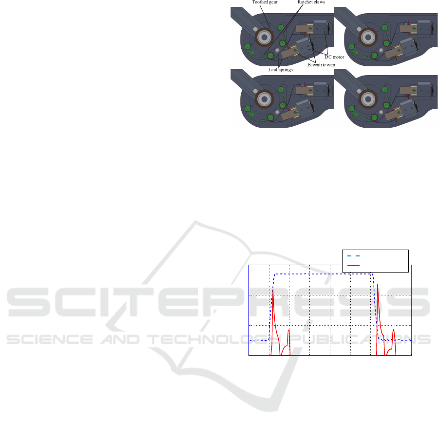
Figure 3: Upper left; Pattern of the meshing of ratchet
mechanism which elbow joint moves freely. Upper right;
Pattern of the meshing of ratchet mechanism which elbow
joint is completely locked. Lower left; Pattern of the mesh-
ing of ratchet mechanism which elbow joint is completely
locked in the direction of the flexion movement and moves
freely in the direction of the extension movement. Lower
right; Pattern of the meshing of ratchet mechanism which
elbow joint is completely locked in the direction of the ex-
tension movement and moves freely in the direction of the
flexion movement.
0 0.2 0.4 0.6 0.8 1 1.2 1.4 1.6
0
1
2
3
0 0.2 0.4 0.6 0.8 1 1.2 1.4 1.6
0
0.1
0.2
0.3
Glove sensor value [V]
Current value of the motor [A]
Time[s]
Glove sensor
Motor current
Figure 4: Monitoring motor current.
tor through two leaf springs. The system is such that
each claw is inserted and removed from the gear. We
use the small DC motor for driving the ratchet mech-
anism. There are two leaf springs of size 0.5[mm]
thickness between the claw of the ratchet and the DC
motor, and the two leaf springs are branched to hold
the eccentric cam that is attached to the output shaft
edge of the DC motor. The eccentric cam has two flat
surfaces on the bottom, and each surface can touch
the upper arm frame. Because the DC motor occurs
resistance when the flat surface of the cam comes into
contact with the upper arm frame by rotating, the elec-
tric current to the motor increases. This system sends
a stop instructiomjn by monitoring the increase in the
electric current levels to allow the system to stop the
motor at the desired position. Figure 4 shows the re-
sults for the motor electric current levels. In this ex-
periment, we lock or unlock by pushing the glove sen-
sor. The electric current levels increase after pushing
ICINCO 2016 - 13th International Conference on Informatics in Control, Automation and Robotics
468
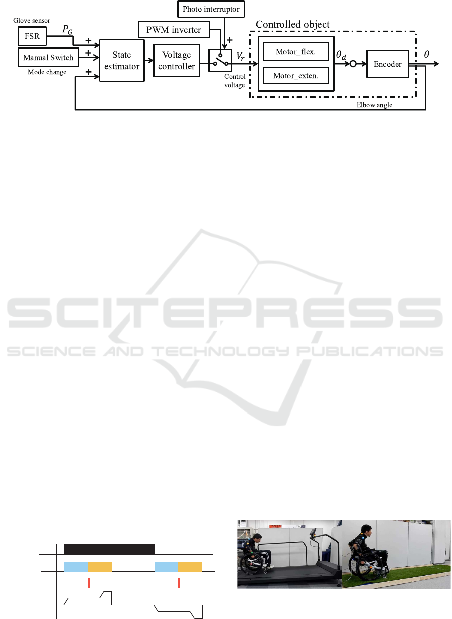
Figure 5: Block diagram of basic control.
the glove sensor. After that, the electric current lev-
els decrease, and then increase again at around 0.3[s].
This is because the flat surface of the cam comes into
contact with the upperframe. In this system, sending
the stop instruction to the motor by monitoring the in-
crease the electric current levels at the second salient.
For this reason, We can reduce power consumption
and the total lock/unlock frequency of this system are
41,000 in one charge.
3.2 Basic Control And Timing Chart
Figure 5 shows a block diagram of the basic control.
We use the FSR406 of the glove sensor, the rotary po-
sition sensor attached to the device and the manual
switch for changing mode. The FSR406 is the force
sensor that can measure the force over a large area,
and the system judges the contact with the wheel rim
or other objects. We use the encoder for sensing the
elbow angle. V
r
is the control voltage, θ
d
is the an-
gle of the device in the block diagram. In the basic
movement, if the output voltage from the signal re-
ceived from the glove sensor is more than 0.847[V],
a voltage instruction is sent to lock the motors. Af-
ter this, the system changes into PWM drive mode
from the signals from the photo interrupters and is
driven at 50% duty ratio. We give consideration for
the cam to make softly make contact with the upper
arm frame by changing the PWM drive mode. This
makes it possible to reduce electricity consumption
by using PWM drive mode to increase the longevity
of the battery. Figure 6 shows the timing chart for this
as a series of events.
If output voltage from the signal received from the
Glove sensor
Control voltage
Photo interrupter
Motor current
(CCW)
(CW)
PWM PWM
Figure 6: Timing chart.
glove sensor is less than 1.8[V], a voltage instruction
is sent to unlock the motors. The system changes the
PWM drive mode from the signals from the photo
interrupters, and sets the drive duty ratio to 50% to
unlock the motor. In other words, the system judges
the state of contact between the wheel rim and the
FSR406 of the glove sensor. If the objects make con-
tact with each other, the motors rotate direction to
lock, and when the FSR406 of the glove sensor de-
taches from the wheel rim, the motors rotate in the
unlock direction. We can change the output voltage
of the glove sensor and the duty ratio. For this reason,
it is possible to set the lock/unlock of the elbow joint
at the timing of the operator.
4 WHEELCHAIR OPERATION
EXPERIMENTS INVOLVING
SUBJECTS WITH CERVICAL
CORD INJURY
The subjects were three people with cervical cord in-
jury. The modified Zancolli classifications were as
follows: Subject 1, C6B1 for the right arm and C5B
for the left arm; Subject 2, C5A for the right arm
and C5B for the left arm; Subject 3, C6 for the right
and left arm. We verified differences between using
and not using the developed device, by using motion
analysis and electromyography for a road with high
resistance and on a slope. The subject who has the
most serious symptoms among the three is not able to
Figure 7: Left; Situation of the experiments on a slope
which set the inclination to 3.4[deg] in accordance with the
barrier-free law of Japan. Right; Situation of the experi-
ments on a lawn way simulated the irregular ground.
Development of Self Support Device and Control for Operating the Wheelchair for Upper Limb Disabled Persons
469
0 1 2 3 4 5 6 7 8 9 10
-1
0
1
Trapezius(Upper)
EMG[V]
0 1 2 3 4 5 6 7 8 9 10
0
0.5
1
1.5
iEMG[V]
0 1 2 3 4 5 6 7 8 9 10
-5
0
5
Biceps brachii
EMG[V]
0 1 2 3 4 5 6 7 8 9 10
0
2
4
5
Time [s]
iEMG[V]
0 1 2 3 4 5 6 7 8 9 10
-1
0
1
Trapezius(Upper)
EMG[V]
0 1 2 3 4 5 6 7 8 9 10
0
0.5
1
1.5
iEMG[V]
0 1 2 3 4 5 6 7 8 9 10
-5
0
5
Biceps brachii
EMG[V]
0 1 2 3 4 5 6 7 8 9 10
0
2
4
5
Time [s]
iEMG[V]
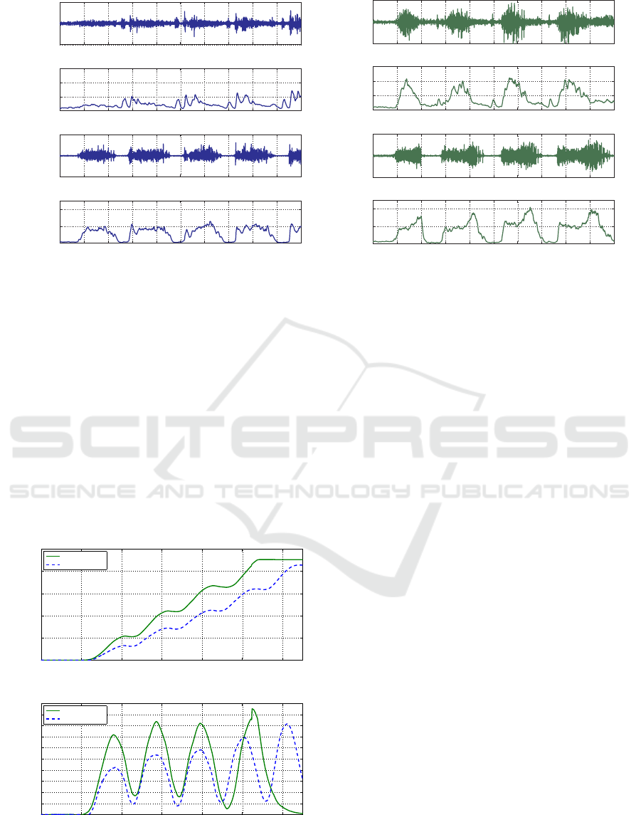
Figure 8: Left; activity of the upper trapezius and biceps brachii muscles without the proposed device by a subject with C5A
for the right arm and C5B for the left arm of cervical cord injury. Right; activity of the upper trapezius and biceps brachii
muscles with the proposed device by a subject with C5A for the right arm and C5B for the left arm of cervical cord injury.
perform extension movement of the elbow joint and
has very weak flexion movement and we describe his
results. This study was approved by an institutional
review board and was performed in accordance with
the Declaration of Helsinki governing human studies.
Figure 7 shows the situation of the experiments.
In the experiment on a slope, we measured the
muscle power of the shoulder circumference by using
an EMG sensor. We used a treadmill to simulate the
slope and set the inclination to 3.4[deg] in accordance
with the barrier-free law of Japan. Figure 8 shows the
muscle power of the shoulder circumference.
0 2 4 6 8 10 12
b
0 2 4 6 8 10 12
b
With device
Without device
With device
Without device
Moving distance[m]
Time[s]
Velocity[m/s]
0
0.5
1
1.5
2
2.5
0
0.05
0.1
0.15
0.2
0.25
0.3
0.35
0.4
0.45
0.5
Figure 9: Experimental results of overlapped waveforms of
operation in grass with/without the proposed device by C5A
and C5B of cervical cord injury.
From the motion analysis results, in the case of
not using the developed robot orthosis, the subject
reached the end of the slope after six strokes and about
13[s]. In the case of using the developed robot ortho-
sis, he reached it after four strokes and about 8[s].
The movement distance per stroke is thus increased.
In the muscle power measurement results, the mus-
cle power of the upper trapezius became more active
than without the device and the muscle power of the
biceps brachii became active in the last part of the op-
eration. This is because the movement distance per
stroke is higher, and the graph shows that continuous
operating power is added in the last part of the op-
eration when the operation occurs at the wheel rim
to the front of the wheelchair. Simulation of irregular
ground includes a rough way, a lawn way, and a gravel
path. We selected using a lawn way. The largest static
coefficient of friction of the artificial lawn which we
set placed in this experiment was approximately 0.07.
We measured the behavior of the wheelchair by using
a motion capture system. Figure 9 shows the behavior
of the wheelchair. The upper graphs show the move-
ment distance, and the lower graphs show the veloc-
ity of the wheelchair. In this experiment, the subject
when using the developed robot orthosis moved a dis-
tance of 2[m] about 2[s] faster than when not using
the developed robot orthosis, and he was able to oper-
ate the wheelchair strongly during the first stroke op-
eration when using the developed robot orthosis. In
the motion analysis results, when not using the de-
veloped robot orthosis, the subject reached a distance
of 2[m] after about five strokes, compared with about
four strokes when using it.
In other words, the movement distance per
ICINCO 2016 - 13th International Conference on Informatics in Control, Automation and Robotics
470

stroke was also increased, and he could operate the
wheelchair strongly.
5 DISCUSSION AND
CONCLUSION
We tested the robot orthosis on three subjects with
cervical cord injury and verified the difference be-
tween using and not using the developed device based
on motion analysis and electromyography at a road
with high resistance and on a slope where it is difficult
to operate a wheelchair. We performed experiments
on a slope and lawn path. With the robot orthosis, the
movement distance per stroke was found to increase
and the muscle power of the upper trapezius became
more active compared to without it, and the muscle
power of the biceps brachii became active in the last
part of operation.
Biceps brachii muscles support flexion of the el-
bow joint, and trapezius muscles support putting up
the shoulder. This set of experiment results show
that the subject can put up his shoulder by using bi-
ceps brachii muscles and also hold the rim of the
wheelchair by using his hand. Therefore, it is indi-
cated that the residual power of his shoulder transmit-
ted to his hand strongly by using the force transmis-
sion orthosis which can lock elbow joint.
In the future, we need to investigate protection
against dust, waterproofing, safety for the device and
make further improvements. It is also necessary to ac-
cumulate more data by increasing the number of test
subjects. Further development is needed to employ
this mechanism and control system for industrial ma-
chinery and other products.
ACKNOWLEDGEMENTS
This work was supported by Projects for Developing
Assistive Products in Ministry of Health Labour and
Welfare of Japan.
REFERENCES
Hsieh, H.-C., Chien, L., and Lan, C.-C. (2015). Mechan-
ical design of a gravity-balancing wearable exoskele-
ton for the motion enhancement of human upper limb.
In 2015 IEEE International Conference on Robotics
and Automation (ICRA), pages 4992–4997.
Juanjuan Zhang, C. C. C. (2015). Passivity and stability
of human-robot interaction control for upper-limb re-
habilitation robots. IEEE Transactions on Robotics,
31:233–245.
M. H. Rahman, M. J. Rahman, O. L. C. M. S. J. P. K.
and Archambault, P. S. (2015). Development of a
whole arm wearable robotic exoskeleton for rehabil-
itation and to assist upper limb movements. Robotica,
33:19–39.
Mao, Y., Jin, X., Dutta, G. G., Scholz, J. P., and Agrawal,
S. K. (2015). Human movement training with a ca-
ble driven arm exoskeleton(carex). IEEE Transactions
on Neural Systems and Rehabilitation Engineering,
23:84–92.
N. Mizutani, T. Watanabe, K. T. Y. and Y. Kobayashi
(2013). A wheelchair operation assistance control for
a wearable robot using with user’s residual function.
In IEEE Int Conf Rehabil Robot.
Tsukahara, A., Hasegawa, Y., Eguchi, K., and Sankai, Y.
(2015). Restoration of gait for spinal cord injury pa-
tients using hal with intention estimator for preferable
swing speed. IEEE Transactions on Neural Systems
and Rehabilitation Engineering, 23:308–318.
T. Watanabe, K. Yano, T. Aoki, and Y. Nishimoto (2011).
Extension motion assistance for upper limb using
proxy-based sliding mode control. In Systems, Man,
and Cybernetics (SMC), 2011 IEEE International
Conference on.
T. Yabunaka, K. Yonezawa, N. Kato, K. Yano, Y.
Kobayashi, T. Aoki, and Y. Nishimoto (2014). A
wheelchair operation with an exoskeletal robot using
user’s residual function. In Micro-NanoMechatronics
and Human Science (MHS), 2014 International Sym-
posium on.
Development of Self Support Device and Control for Operating the Wheelchair for Upper Limb Disabled Persons
471
