
State Feedback Control Solutions for a Mechatronics System with
Variable Moment of Inertia
Alexandra-Iulia Szedlak-Stinean
1
, Radu-Emil Precup
1
, Stefan Preitl
1
, Emil M. Petriu
2
and Claudia-Adina Bojan-Dragos
1
1
Department of Automation and Applied Informatics, Politehnica University of Timisoara,
Bd. V. Parvan 2, 300223, Timisoara, Romania
2
School of Electrical Engineering and Computer Science, University of Ottawa,
800 King Edward, K1N 6N5, Ottawa, ON, Canada
Keywords: Experimental Results, Flexible Drive Dynamics, Mechatronics Application, PID Controllers, Position
Control, Rigid Body Dynamics, Variable Moment of Inertia.
Abstract: This paper presents details regarding the design of two state feedback control (SFC) solutions for the
position control of a mechatronics application represented by the Model 220 Industrial Plant Emulator.
Since SFC is not effective in terms of zero steady-state control error, the SFC structure of both solutions is
inserted in a control loop that contains a PID controller with or without low-pass filter. This leads to the two
SFC solutions proposed in this paper and dedicated to mechatronics applications with variable moment of
inertia. The PID controllers are tuned by the Modulus Optimum method to ensure high control system
performance expressed as increased phase margins and improved tracking performance. The performance of
the proposed SFC solutions is illustrated by case studies that deal with experimentally identified parameters
in two situations, rigid body dynamics and flexible drive dynamics. Simulation and experimental results
obtained for the three significant values of the moment of inertia of the load disk are given.
1 INTRODUCTION
Mechatronics systems are successfully used in many
industrial and non-industrial applications because of
their initial simple and robust structure. The design
steps of control structures for mechatronics
applications are (Isermann, 2005; Bishop, 2007): 1.
accept a simplified system representation, 2. set the
control system performance, 3. design the
measurement instrumentation including state
estimation. 4. generate dynamic behaviours in special
situations, 5. develop convenient control algorithms,
and 6. perform the fault diagnosis.
The mechatronics application considered in this
paper is the Model 220 Industrial Plant Emulator
(M220IPE) laboratory equipment, which is a
complex and nonlinear device that illustrates and
models industrial processes with variable inertia
(ECP, 2010; Stinean et al., 2013a, 2013b). The main
advantages of M220IPE are the possibility to adjust
the dynamic parameters and the ability to introduce
and remove non-ideal proprieties in a controlled
manner. M220IPE is also advantageous from the
experimental testing point of view: it does not allow
a continuous variation (during operation) of the
moment of inertia, which in turn determines the
validation at important operating points, and a
reduced flexibility to modifications of the control
algorithms.
Some well acknowledged control solutions for
M22OIPE will be briefly analyzed as follows. The
disturbances are estimated in (Gao et al., 2001) using
an extended state observer and compensated at each
sampling period. Three state observer design
techniques including high-gain observers, sliding
mode observers and extended state observers are
discussed in (Wang and Gao, 2003). The design of a
static anti-windup compensator is suggested in
(Takamatsu et al., 2010) on the basis of the circle
criterion that leads to numerically solved linear
matrix inequalities. A data-driven design method of
a PID controller and a robust feedback control
designed for mechanisms with backlash are given in
(Saeki and Kishil, 2011). Fuzzy and neuro-fuzzy
control solutions are investigated in (Stinean et al.,
2013a, 2013b, 2015).
This paper gives details on the design and
implementation of two state feedback control (SFC)
458
Szedlak-Stinean, A-I., Precup, R-E., Preitl, S., Petriu, E. and Bojan-Dragos, C-A.
State Feedback Control Solutions for a Mechatronics System with Variable Moment of Inertia.
DOI: 10.5220/0005988904580465
In Proceedings of the 13th International Conference on Informatics in Control, Automation and Robotics (ICINCO 2016) - Volume 2, pages 458-465
ISBN: 978-989-758-198-4
Copyright
c
2016 by SCITEPRESS – Science and Technology Publications, Lda. All rights reserved

solutions for M220IPE. These solutions include a
PID controller with a low-pass filter in case of rigid
body dynamics and a PID without filter in case of
flexible drive dynamics.
This paper offers four new contributions: 1. the
mathematical modelling of the servo system
M220IPE and the interpretation of these models as
benchmark type mathematical models (MMs), 2. the
design of two SFC solutions, 3. the experimental and
simulated validation of the SFC structures with PID
controllers in nine case studies dedicated to the
position control of M220IPE with rigid body
dynamics and three case studies with flexible drive
dynamics, and 4. the comparative analysis of all
control structures.
This paper is structured as follows: an overview
on the numerical values of the system parameters is
given in the next section. The MMs in case of rigid
body dynamics and flexible drive dynamics are also
defined. The design and implementation of the SFC
solutions are discussed in Section 3. The simulation
and experimental results are presented in Section 4.
A comparison of the control systems performance is
included. The conclusions are offered in Section 5.
2 MODEL 220 INDUSTRIAL
PLANT EMULATOR
2.1 Numerical Values of System
Parameters
Since the laboratory setup built around M220IPE
can only provide discontinuous changes of the
moment of inertia, three case studies described
briefly in (Stinean et al., 2015) have been
implemented, tested by simulation and experiments
and analyzed. The proposed control solutions will be
designed for three significant values of the moment
of inertia of the load disk, J
load
: the initial value
J
load,init
=0.0065kgm
2
(without weights on the load
disk), the average value J
load,avg
=0.01474kgm
2
(four
brass weights of 0.2 kg each), and the maximum
value J
load,max
=0.0271kgm
2
(four brass weights of 0.5
kg each). Based on past experience (Stinean et al.,
2013a, 2013b, 2015) nine combinations between
process parameters and controller parameters are
possible. The following notations were used to
analyze and develop the proposed control solutions:
,12/,/6
, ,
,
'
____
___
pdplpd
backlashploadpdrivepploadw
loaddloaddrivewdriveddrive
ngrnngr
JJJJJ
JJJJJ
(1)
where: J
drive
– the inertia of the drive disk, J
d_drive
–
the inertia of the bare drive disk, drive motor,
encoder, drive disk/motor belt and pulleys, J
w_drive
–
the inertia associated with the brass weights at the
drive disk, J
load
– the inertia of the load disk, J
d_load
– the inertia of the bare load disk, disturbance motor,
encoder, load disk/motor belt and pulleys, J
w_load
–
the inertia associated with the brass weights at the
load disk, J
p
– the pulley inertia, J
p_drive
, J
p_load
– the
inertia associated with the pulleys in the masses
assembly, J
p_backlash
– the inertia of the backlash
mechanism, gr – the drive train gear ratio, gr
’
– the
partial gear ratio between the idler pulley assembly
and the drive disk, n
pd
– the number of teeth on
bottom pulley, n
pl
– the number of teeth on top
pulley, c
1
,c
2
– the drive and load friction (modelled
as viscous), c
12
– the coupled friction, and k – the
rotary (torsional) spring constant. The parameters of
the servo system M220IPE used in the SFC design
are (ECP, 2010; Stinean et al., 2013a)
Nm/rad. 45.8 ,Nm/rad/ 017.0
Nm/rad/s, 05.0 Nm/rad/s, 004.0
36),=n(n kgm 000039.0J J
24),=n(n kgm 000008.0J J
,m) 0.1rat kg 0.5 (4 kgm 0206.0
,m) 0.1rat kg 0.2 (4 kgm 00824.0
,m) 0.05rat kg 0.5 (4
kgm 00561.0
,m) 0.05rat kg 0.2 (4 kgm 0021.0
,kgm 000031.0
,kgm 0065.0 ,kgm 00040.0
2
plpd
2
__
plpd
2
__
wl
2
_
wl
2
_
wd
2
_
wd
2
_
2
_
2
_
2
_
ksc
cc
J
J
J
J
J
JJ
12
1
loadpdrivep
loadpdrivep
loadw
loadw
drivew
drivew
backlashp
loadddrived
(2)
2.2 Mathematical Models of M220IPE
This sub-section presents the dynamic equations
used in the process MM in two situations, rigid body
dynamics and flexible drive dynamics.
2.2.1 Rigid Body Dynamics
The MM of M220IPE with rigid body dynamics
(ECP, 2010; Stinean et al., 2013a) is obtained from
the balance equation in matrix form
.
,
0
0
,
0
0
,,
*
*
*
*
2
1
D
D
load
drive
load
drive
Tgr
T
c
c
J
J
Tc
JθTθcθJ
(3)
with θ
1
=grθ
2
or θ
1
=gr
’
θ
p
, where:
θ
1
– the drive disk
position, θ
2
– the load disk position, θ
p
– the idler
State Feedback Control Solutions for a Mechatronics System with Variable Moment of Inertia
459

pulleys position, J
drive
*
– the total inertia reflected to
the drive disk, J
load
*
– the total inertia reflected to the
load disk, c
drive
*
, c
load
*
– the total reflected friction
constants, and T
D
– drive torque, and the expressions
of the parameters in (3)
. ,)(
,)/(
,)()(
2
2
1
*2
21
*
2'2*
22'*
cgrccgrccc
JgrgrJgrJJ
grJgrJJJ
loaddrive
loadpdriveload
loadpdrivedrive
(4)
The state-space MM of M220IPE with rigid body
dynamics with θ
1
as the process output is
,,
1
1
x
xC
TBxAx
y
(5)
with the matrix expressions
].0 1[,
/1
0
,
/0
10
***
CBA
drivedrivedrive
JJc
(6)
Applying the Laplace transform to (3) and accepting
zero initial conditions, the process transfer function
(t.f.) is
)]./(/[)/1()(/)(
***
1 drivedrivedriveD
JcssJsTs
(7)
2.2.2 Flexible Drive Dynamics
The balance equation in matrix form enables the
derivation of the MM of M220IPE with flexible
drive dynamics (ECP, 2010; Zheng et al., 2012):
.
1
,
0
,
,
0
0
, ,
1
1
2
122
1
12
1
12
2
121
*
2
1
gr
gr
gr
k
T
ccgrc
grcgrcc
J
J
D
load
drive
K
Tc
JθTKθθcθJ
(8)
Considering θ
1
as the process output, the state-space
MM of M220IPE with flexible drive dynamics is
given in (5), with the matrices
],0 0 0 1[ ,][
,][ ,] [
4...11
4...1,2211
CB
Ax
ii
jiij
T
b
a
(9)
with the matrix elements
.0 ,0 ,/1 ,0 ,/)
( ,/ ,/
,/ 1, 0, 0,
,0,/ ,/
,/)( ,/
0, 0, 1, ,0
4131
*
211112
24443
1
1242
1
41343332
31
*1
1224
*1
23
*2
12122
*2
21
14131211
bbJbbJc
caJkaJgrca
Jkgraaaa
aJgrcaJkgra
JgrccaJkgra
aaaa
driveload
loadload
load
drivedrive
drivedrive
(10)
Applying the Laplace transform to (8) and accepting
zero initial conditions, the process t.f. is
.0
,)/( ,)/(
)/( )],/(
[)( ,
,)(
),(/])([)(/)(
0
2
211
2
212121
21
2*
2
2
12
1122
*
3
*
4
01
2
2
3
3
4
4
122
2
1
n
grkckcngrcccc
ccgrkJkJngrc
cJccJnJJn
nsnsnsnsnsD
sDksccsJsTs
loaddrive
loaddriveloaddrive
loadD
(11)
The t.f.s given in (7) and (11) and the matrix
coefficients for three significant values of the
moment of inertia of the load disk are given in
Tables 1 and 2.
3 STATE FEEDBACK CONTROL
SOLUTIONS
3.1 Classical SFC Solutions
The SFC structure is illustrated as the internal
control loop in Figure 1. It is next extended and
included in a control loop with a PID controller in
order to ensure a zero steady-state control error as
discussed in sub-section 3.2. The state feedback gain
matrix k
c
T
in both situations is of proportional type.
The state feedback controller includes an
additional amplifier with the gain set to k
AS
=1.
Figure 1 leads to
. ,
xASxxx
ekuywe
(12)
The pole placement method is applied to compute
k
c
T
using three sets of poles imposed, each for the
three significant values of the moment of inertia of
the load disk, i.e., J
load,init
, J
load,avg
, J
load,max
. The
notation y
x
= k
c
T
x is used in Figure 1. This leads to
the state-space MM of the SFC structure
, ,
AS
AS
x
k
y
wk
T
cx
x
kBAA
xC
BxAx
(13)
where A
x
is the matrix of the inner SFC loop. The
state feedback gain matrix of M220IPE with rigid
body dynamics is according to Table 3, columns 4
and 5 and the state feedback gain matrix of
M220IPE with flexible drive dynamics is according
to Table 3, columns 10, 11, 12 and 13. The closed-
loop system poles (i.e., the inner SFC loop) are
given Table 3, columns 2 and 3 for rigid body
dynamics and in columns 6, 7, 8 and 9 for flexible
drive dynamics. The t.f. of the inner SFC loop is
ICINCO 2016 - 13th International Conference on Informatics in Control, Automation and Robotics
460

,
)1)(1)(1)(1(
)21(
)1)(1(
)()(
4321
22
21
1
sTsTsTsT
sTsTk
or
sTsT
k
ssH
bbbSFC
SFC
xSFC
BAIC
(14)
where I is the second-order (or fourth-order) identity
matrix, k
SFC
is the inner SFC loop gain, T
1
(or T
1
, T
2
)
is (are) the large time constant, and T
2
(or T
3
, T
4
) is
(are) the small time constant (s).
3.2 Design and Implementation of PID
Controllers
The first SFC solution uses a PID controller with a
low-pass filter with the generic t.f. and parameters
,9.0,,
),2/(1),1/(
)1)(1)(/()(
22211
2
21
cfcc
SFCcf
cccc
TTTTTT
TkksT
sTsTsksH
(15)
where k
c
is the controller gain, T
c1
and T
c2
are the
controller time constants, and T
f
is the filter time
constant. The control algorithm is designed and tuned
in terms of Kessler’s Modulus Optimum method
(MO-m) referred in (Åström and Hägglund, 1995).
Using the backwards difference method, the
continuous-time PID controller with the continuous-
time t.f. H
c
(s) is discretized resulting in the discrete-
time t.f. H
c
(z
-1
)
,),2(,
)],()([
,),)((
,)(
210
12211
212210
2
2
1
10
2
2
1
10
1
fsfsf
sccsccc
cccscscc
c
TpTTpTTp
TTTTTTkq
TTkqTTTTkq
zpzpp
zqzqq
zH
(16)
where T
s
=0.004s is the sampling period. The
numerical values related to SFC structure and the
PID controllers for three significant operating points
are given in Table 4.
Table 1: State-space MM matrices and transfer functions expressions of M220IPE with rigid body dynamics.
Moment of inertia Matrices A, B and C Process transfer function θ
1
(s)/T
D
(s)
J
load,init
01,
7036
0
,
8.630
10
CBA
)63.8(
7036
ss
J
load,avg
01,
4362
0
,
5.350
10
CBA
)35.5(
4362
ss
J
load,max
01,
2741
0
,
37.30
10
CBA
)37.3(
2741
ss
Table 2: State-space MM matrices and transfer functions expressions for M220IPE with flexible drive dynamics.
Moment of
inertia
Matrices A, B and C Process transfer function θ
1
(s)/T
D
(s)
J
load,init
]0001[,
0
0
13850
0
,
307.10
1
13.10
0
1300
0
5036
0
654.0
0
068.12
1
325
0
1259
0
CBA
)220782.267737.22(
)1300307.10(13850
23
2
ssss
ss
J
load,avg
]0001[,
0
0
13850
0
,
59.4
1
13.10
0
579
0
5036
0
3.0
0
068.12
1
145
0
1259
0
CBA
)4.98277.189365.16(
)57959.4(13850
23
2
ssss
ss
J
load,max
]0001[,
0
0
13850
0
,
47.2
1
13.10
0
312
0
5036
0
157.0
0
068.12
1
9.77
0
1259
0
CBA
)4.52904.159953.14(
)31247.2(13850
23
2
ssss
ss
State Feedback Control Solutions for a Mechatronics System with Variable Moment of Inertia
461
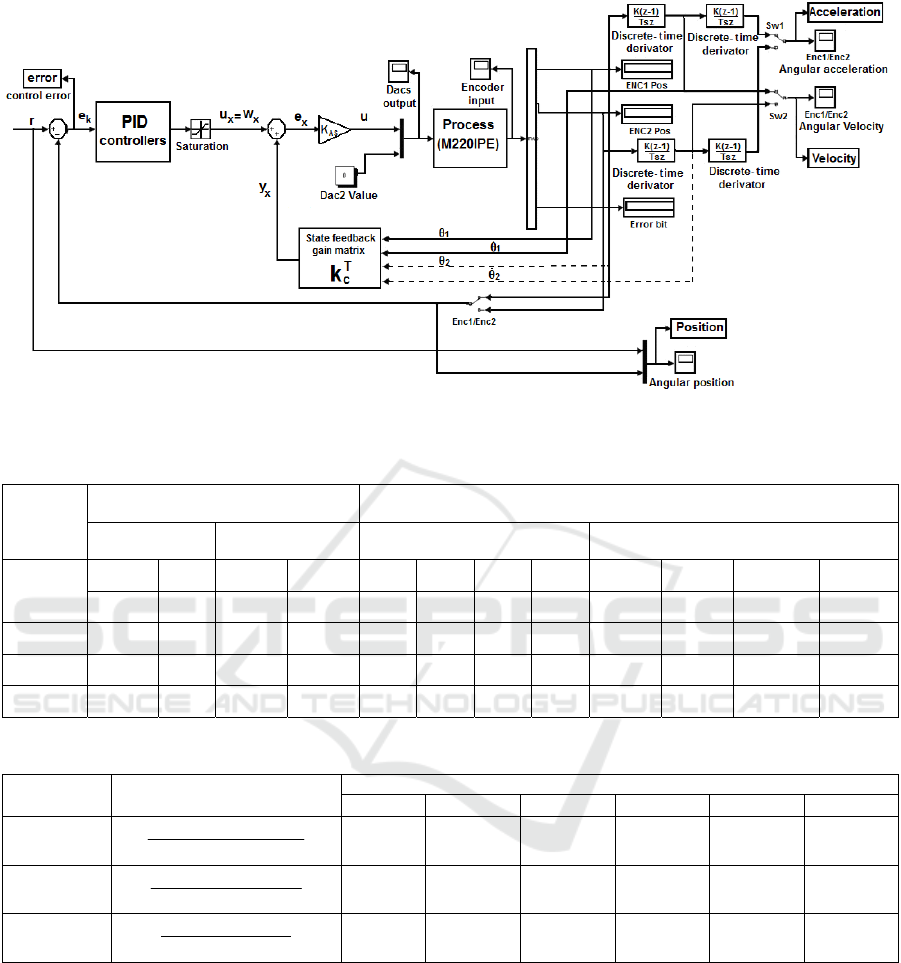
Figure 1: Control structure of M220IPE with rigid body dynamics and flexible drive dynamics.
Table 3: Selected poles and state feedback gain matrix numerical values.
Moment
of inertia
Rigid body dynamics Flexible drive dynamics
Selected poles
State feedback gain
matrix
Selected poles State feedback gain matrix
1
2 3 4 5 6 7 8 9 10 11 12 13
p
1
*
p
2
*
k
c1
k
c2
p
1
*
p
2
*
p
3
*
p
4
*
k
c1
k
c2
k
c3
k
c4
J
load,init
-20 -11
0.0313 0.0032 -20 -11 -105 -110 0.9735 0.0161 -3.3304 -0.0036
J
load,avg
-20 -7
0.0321 0.0050 -20 -7 -50 -55 0.2385 0.0083 -0.7600 0.0002
J
load,max
-20 -5
0.0365 0.0079 -20 -5 -30 -35 0.0712 0.0054 -0.1873 0.0018
Table 4: SFC structure t.f.s and numerical values of PID controllers’ parameters for rigid body dynamics.
Moment of
inertia
SFC structure t.f. H
SFC
(s)
Parameters of PID controllers
q
0
q
1
q
2
p
0
p
1
p
2
J
load,init
)05.01)(0909.01(
9818.31
ss
0.0016 -0.0030 0.0014 0.0490 -0.0940 0.0450
J
load,avg
)05.01)(1429.01(
1571.31
ss
0.0025 -0.0048 0.0023 0.0490 -0.0940 0.0450
J
load,max
)05.01)(2.01(
41.27
ss
0.0040 -0.0077 0.0036 0.0490 -0.0940 0.0450
Since the M220IPE with flexible drive dynamics
is a fourth-order system, the second SFC solution
uses a PID controller to compensate two large time
constants. The generic continuous-time t.f. of the
PID controller is given in (15). The requirement to
ensure zero steady-state control error is fulfilled by
the I component of the PID controller. The MO-m is
also applied to tune the three PID controllers with
fixed parameter values. Setting the value of the
sampling period to T
s
=0.004s, the continuous-time
PID controller is discretized using the backwards
difference method and the discrete-time parameters
q
0
, q
1
and q
2
are according to relation (16), the only
differences are in p
0
and p
1
(p
0
=T
s
and p
1
=-T
s
)
parameters. The numerical values of the parameters
of the PID controllers used in simulations and
experiments are presented in Table 5.
4 SIMULATION AND
EXPERIMENTAL RESULTS
The two SFC solutions described in Section 3 have
ICINCO 2016 - 13th International Conference on Informatics in Control, Automation and Robotics
462
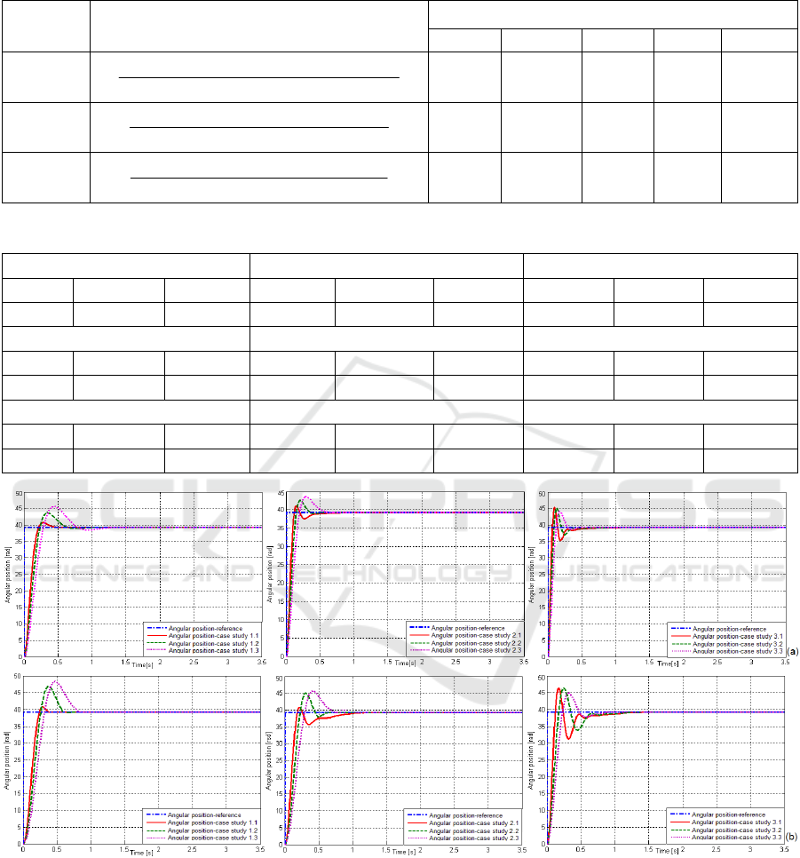
Table 5: SFC structure t.f.s and numerical values of PID controllers’ parameters for flexible drive dynamics.
Moment of
inertia
SFC structure t.f. H
SFC
(s)
Parameters of PID controllers
q
0
q
1
q
2
p
0
p
1
J
load,init
)0091.01)(0095.01)(05.01)(0909.01(
)00077.00079.01(0838.7
2
ssss
ss
0.0038 -0.0072 0.0034 0.0040 -0.0040
J
load,avg
)0182.01)(02.01)(05.01)(1429.01(
)0017.00079.01(8286.20
2
ssss
ss
0.0040 -0.0075 0.0036 0.0040 -0.0040
J
load,max
)0286.01)(0333.01)(05.01)(2.01(
)0032.00079.01(0952.41
2
ssss
ss
0.0028 -0.0053 0.0025 0.0040 -0.0040
Table 6: Performance indices achieved by the control systems with PID controllers.
Case study 1.1 Case study 1.2 Case study 1.3
σ
1
t
1
t
s
σ
1
t
1
t
s
σ
1
t
1
t
s
5.05% 0.2209 0.4928 18.75% 0.266 0.7717 20.625% 0.3281 0.8898
Case study 2.1 Case study 2.2 Case study 2.3
σ
1
t
1
t
s
σ
1
t
1
t
s
σ
1
t
1
t
s
1% 0.1867 1.3021 12.5% 0.2306 0.6901 15% 0.2806 0.7202
Case study 3.1 Case study 3.2 Case study 3.3
σ
1
t
1
t
s
σ
1
t
1
t
s
σ
1
t
1
t
s
17.1% 0.1236 1.4997 16.99% 0.1707 1.2411 13% 0.2428 0.7625
Figure 2: Simulation (a) and experimental (b) results regarding the behaviour of SFC structures with PID controllers
designed for M220IPE with rigid body dynamics: case studies 1.1-1.3, 2.1-2.3 and 3.1-3.3.
State Feedback Control Solutions for a Mechatronics System with Variable Moment of Inertia
463

Figure 3: Simulation (q) and experimental (b) results regarding the behaviour of SFC structures with PID controllers
developed for M220IPE with flexible drive dynamics: case study 1.1, 2.2 and 3.3.
been implemented and tested on M220IPE laboratory
as position control systems. The results obtained on
the M220IPE laboratory equipment with rigid body
dynamics are presented in Figure 2. Three SFC
structures – each for every moment of inertia of the
load disk – have been tested on the nonlinear system
and validated by simulation and real-time
experiments. Analyzing the comparative results
illustrated in Figure 2 and the performance
synthesized in Table 6 for the experimental results, it
can be concluded that the best reference tracking and
control system performance has been obtained in the
case studies 1.1, 2.2 and 3.3.
The three most favourable case studies were
tested for M220IPE with flexible drive dynamics, and
the results are presented in Figure 3. Both simulation
and experimental results show similar performance
indices in terms of the settling time values, the first
settling time values and the overshoot values as
follows: case study 1.1: σ
1
≈0%, t
1
≈0.934s, t
s
≈1s;
case study 2.2: σ
1
≈11.25%, t
1
≈0.252s, t
s
≈1.2308s;
case study 3.3: σ
1
≈15.5%, t
1
≈0.267s, t
s
≈1.3916s. The
analysis of the set of results presented for the two
SFC solutions points out that all tested control
solutions provide relatively good reference tracking.
The comparative results given in Figures 2 and 3
prove that the PID controllers contribute in average
to both good dynamic performance and robustness
with respect to at least one process parameter.
5 CONCLUSIONS
This paper has given design and implementation
details on two SFC solutions for a mechatronics
application with rigid body dynamics and flexible
drive dynamics for three significant values of the
moment of inertia on the load disk. The simulation
and real-time experimental results show that our
SFC structures exhibit good control system
performance indices that should be improved in
critical applications. The main advantages of the
new results given in this paper are the simplicity of
the SFC structure with a reduced number of
parameters and the transparency of the design
approach.
Our SFC solutions can be viewed as a support
for other control solutions including fuzzy, neural,
sliding mode and adaptive control (Blažič et al.,
2010; Precup et al., 2009, 2012; Ruano et al., 2002).
The performance can be improved by inserting
sensitivity, robustness objectives and constraints
(Casavola et al., 2014; Gutiérrez-Carvajal et al.,
2016). The pole placement method applied in this
paper can be replaced by the optimal design and
tuning by means of classical or modern optimization
algorithms (Bandarabadi et al., 2015; Johanyák,
2015; Menchaca-Mendez and Coello Coello, 2016).
This has not been investigated, but it represents a
subject of future research. Future research will also
be focused on applications to other illustrative
nonlinear processes.
ACKNOWLEDGEMENTS
This work was supported by grants from the
Partnerships in priority areas – PN II program of the
ICINCO 2016 - 13th International Conference on Informatics in Control, Automation and Robotics
464

Romanian Ministry of National Education and
Scientific Research – the Executive Agency for
Higher Education, Research, Development and
Innovation Funding (UEFISCDI), project numbers
PN-II-PT-PCCA-2013-4-0544 and PN-II-PT-PCCA-
2013-4-0070, the Partnerships in priority areas – PN
II program of the Romanian National Authority for
Scientific Research ANCS, CNDI – UEFISCDI,
project number PN-II-PT-PCCA-2011-3.2-0732, the
Romanian National Authority for Scientific
Research, CNCS – UEFISCDI, project numbers PN-
II-ID-PCE-2011-3-0109 and PN-II-RU-TE-2014-4-
0207, and from the NSERC of Canada.
REFERENCES
Åström, K. J., Hägglund, T., 1995. PID Controllers
Theory: Design and Tuning. Research Triangle Park,
NC: Instrument Society of America.
Bandarabadi, M., Rasekhi, J., Teixeira, C. A., Netoff, T. I.,
Parhi, K. K., Dourado, A., 2015. Early seizure detection
using neuronal potential similarity: a generalized low-
complexity and robust measure. International Journal
of Neural Systems. 25, 1-18.
Bishop, R. H., 2007. The Mechatronics Handbook. Boca
Raton, FL: CRC Press, 2
nd
edition.
Blažič, S., Matko, D., Škrjanc, I., 2010. Adaptive law with a
new leakage term. IET Control Theory & Applications.
4, 1533-1542.
Casavola, A., Garone, E., Tedesco, F., 2014. Improved feed-
forward command governor strategies for constrained
discrete-time linear systems. IEEE Transactions on
Automatic Control. 59, 216-223.
ECP (2010). Industrial Emulator/Servo Trainer Model
220 System, Testbed for Practical Control Training.
Bell Canyon, CA: Educational Control Products.
Gao, Z., Hu, S., Jiang, F., 2001. A novel motion control
design approach based on active disturbance rejection.
In Proceedings of 40
th
IEEE Conference on Decision
and Control. Orlando, FL, USA, 5, 4877-4882.
Gutiérrez-Carvajal, R. E., de Melo, L. F., Rosário, J. M.,
Tenreiro Machado, J. A., 2016. Condition-based
diagnosis of mechatronic systems using a fractional
calculus approach. International Journal of Systems
Science. 47, 2169-2177.
Isermann, R., 2005. Mechatronic Systems: Fundamentals.
Berlin, Heidelberg, New York: Springer-Verlag.
Johanyák, Z. C., 2015. A simple fuzzy logic based power
control for a series hybrid electric vehicle. In
Proceedings of 9
th
IEEE European Modelling
Symposium on Mathematical Modelling and Computer
Simulation. Madrid, Spain, 207-212.
Menchaca-Mendez, A., Coello Coello, C. A., 2016.
Selection mechanisms based on the maximin fitness
function to solve multi-objective optimization problems.
Information Sciences. 332, 131-152.
Precup, R.-E., Dragos, C.-A., Preitl, S., Radac, M.-B.,
Petriu, E. M., 2012. Novel tensor product models for
automatic transmission system control. IEEE Systems
Journal. 6, 488–498.
Precup, R.-E., Tomescu, M. L., Preitl, S., 2009. Fuzzy logic
control system stability analysis based on Lyapunov’s
direct method. International Journal of Computers,
Communication & Control. 4, 415–426.
Ruano, A. E. B., Cabrita, C., Oliveira, J. V., Kóczy, L. T.,
2002. Supervised training algorithms for B-Spline
neural networks and neuro-fuzzy systems.
International Journal of Systems Science. 33, 689-711.
Saeki, M., Kishi, R., 2011. A data-driven PID control
design by linear programming for stable plants. In
Proceedings of 18
th
IFAC World Congress. Milano,
Italy, 7420-7425.
Stinean, A.-I., Bojan-Dragos, C.-A., Precup, R.-E., Preitl,
S., Petriu, E. M., 2015. Takagi-Sugeno PD+I fuzzy
control of processes with variable moment of inertia.
In Proceedings of 2015 International Symposium on
Innovations in Intelligent Systems and Applications.
Madrid, Spain, 1-8.
Stinean, A.-I., Preitl, S., Precup, R.-E., Dragos, C.-A.,
Radac, M.-B., Petriu, E. M., 2013a. Modeling and
control of an electric drive system with continuously
variable reference, moment of inertia and load
disturbance. In Proceedings of 9
th
Asian Control
Conference. Istanbul, Turkey, 1-6.
Stinean, A.-I., Preitl, S., Precup, R.-E., Dragos, C.-A.,
Radac, M.-B., Petriu, E. M., 2013b. Low-cost neuro-
fuzzy control solution for servo systems with variable
parameters. In Proceedings of 2013 IEEE
International Conference on Computational
Intelligence and Virtual Environments for
Measurement Systems and Applications. Milano, Italy,
156-161.
Takamatsu, S., Wasiwitono, U., Saeki, M., Wada, N.,
2010. Anti-windup compensator design considering
behavior of controller state. In Proceedings of 2010
IEEE International Conference on Control
Applications. Yokohoma, Japan, 1963-1968.
Wang, W., Gao, Z., 2003. A comparison study of
advanced state observer design techniques. In
Proceedings of 2003 American Control Conference.
Denver, CO, USA, 6, 4754-4759.
Zheng, Q., Gao, L. Q., Gao, Z., 2012. On validation of
extended state observer through analysis and
experimentation. Journal of Dynamic Systems,
Measurement, and Control. 134, 024505.1–024505.6.
State Feedback Control Solutions for a Mechatronics System with Variable Moment of Inertia
465
