
Evaluation of Hip Kinematics Influence on the Performance of a
Quadrupedal Robot Leg
Navvab Kashiri, Arash Ajoudani, Darwin G. Caldwell and Nikos G. Tsagarakis
Department of Advanced Robotics, Istituto Italiano di Tecnologia, Via Morego 30, 16163 Genova, Italy
Keywords:
Leg Kinematics Design, Quadrupeds, Legged Robots, Force Manipulability/Polytope, Dynamic
Manipulability/Polytope.
Abstract:
As a major inspiration of biologically inspired systems, multi-legged robots have been developed due to their
superior stability feature resulting from their large support polygon. The leg design of a majority of such robots
is motivated by the skeleton of vertebrates such as dogs, or that of invertebrates such as spiders. Despite a
wide variety of multi-pedal robots on the basis of the two aforesaid leg designs, a thorough comparison of
the two underlying design principles remains to be done. This work addresses this problem and presents a
comparative study for the two mammal-like and spider-like designs by looking at the joint torque profile, the
responsive motion of the legs, and the thrust force applied by the robot. To this end, a set of performance
indexes are defined based on the gravity compensation torque, the dynamic manipulability polytope and the
force polytope, and evaluated in various leg configurations of the two designs.
1 INTRODUCTION
Robots have been widely employed in industrial
settings during the past four decades, offering a
range of functionality from manufacturing to food
processing. While a majority of such platforms are
manipulators mounted on fixed/wheeled bases, there
are many scenarios that the robot needs to operate
in complex, unstructured, and dynamically changing
environments, where the human-/animal-like degrees
of mobility and agility would be essential (Caldwell
et al., 2014). Such a demand has created
new opportunities for the legged robots whose
functionality is not limited to naturally or artificially
smoothed terrains. Hence, an increasing worldwide
attention has been given to the development of pedal
robots within the past decade.
Even though the underlying anthropomorphic
structure of humanoid robots has illustrated the
potential of generating human-like mobility and
manipulation skills (Negrello et al., 2016; Bagheri
et al., 2015), the control of balance while performing
highly dynamic tasks or walking along rough terrains
is troublesome and still appears in a developing
stage. Multi-pedal robots (e.g. quadrupeds and
hexapods), on the other hand, present a higher level
of balancing performance due to a larger support
polygon compared to the bipedal ones.
The BigDog quadrupeds (Raibert et al., 2008)
developed by the Boston Dynamics, Inc., is a
renowned example of walking robots built for
outdoor applications, whose design is inspired by
the skeleton of mammals. The StarlETH (Hutter
et al., 2012), LittleDog (Shkolnik et al., 2010),
XDOg (Xie et al., 2014), MIT Cheetah (Seok
et al., 2013), IIT HyQ (Semini et al., 2011)
and Cheetah-cub (Spr
¨
owitz et al., 2013) are other
examples of quadrupeds motivated by the mammalian
morphology. Alternative design of the robot legs is
inspired by the leg structure of insects and arachnids
such as spider (Ho et al., 2007; Gasparetto et al.,
2008), examples of which can be found in the design
of TITAN quadruped (Kato and Hirose, 2001), LAVA
(Zielinska and Heng, 2003), LAURON V (Roennau
et al., 2013), PUT Hexapod Robots (Belter et al.,
2015), MRWALLSPECT-III (Kang et al., 2003), and
MiniQuad I (Chen et al., 2008).
Despite the fast growing interest in the application
of the quadruped robots in various real-world
scenarios, the literature still fails to present a through
comparative study for the two aforementioned
design principles, especially regarding the dynamic
capabilities of the robot. Previous work in this area
mainly concerns kinematic considerations (Kar, 2003;
Chen et al., 2006; Zielinska, 2013), e.g. analysis of
the optimum inclination angle of the hip joint on the
Kashiri, N., Ajoudani, A., Caldwell, D. and Tsagarakis, N.
Evaluation of Hip Kinematics Influence on the Performance of a Quadrupedal Robot Leg.
DOI: 10.5220/0005986502050212
In Proceedings of the 13th International Conference on Informatics in Control, Automation and Robotics (ICINCO 2016) - Volume 1, pages 205-212
ISBN: 978-989-758-198-4
Copyright
c
2016 by SCITEPRESS – Science and Technology Publications, Lda. All rights reserved
205

basis of kinematics manipulability (Roennau et al.,
2013). With that being said, this paper will attempt
to present a deeper analysis of the mammal-like
and spider-like legs for quadrupedal robots, although
it can be exploited for other pedal platforms in a
similar fashion. In this direction, a group of indexes
describing the statics and dynamics of the robot
is defined and evaluated throughout the workspace
of the robot. The proposed indexes are based on
three criteria: the torque capacity computed from the
gravity compensation torque of joints representing the
static energy consumption of the system; a set of
measures derived from the dynamic manipulability of
legs describing the reactive capabilities of the robot;
and others extracted from the force manipulability
of legs analysing the capabilities of the robot to
avoid slippage. The study of the force/dynamic
manipulability is achieved through the definition of
the corresponding polytopes (Chiacchio et al., 1997),
to present the exact boundaries of the manipulator in
a given configuration, subject to the actuator torque
bounds, in comparison to alternative less-accurate
representations such as ellipsoids (Yoshikawa, 1985).
The rest of this paper is organized as follows:
Section II describes the problem to be discussed
in this paper. The corresponding formulation is
presented in Section III, including the kinematics
and dynamics background, and the elaboration
of the three groups of criteria utilised for this
comparison study. Simulation analysis of the two
mammal-/spider- like leg design quadrupeds are
illustrated in Section IV, and the pertinent results
are discussed. Finally, Section V addresses the
conclusion and future works.
2 PROBLEM STATEMENT
A majority of quadrupedal robots make use of two
pre-dominant kinematics arrangements inspired by
the mammal or spider type legs, as noted in the
literature review. Concerning the first three joints of
the leg related to the hip and the knee, they can be
described as follows
• mammal-like legs: A roll hip joint permitting the
abduction/Adduction motion is used for the first
joint, in addition to two pitch joints for generating
flexion/extension motion of hip and knee joints.
• spider-like legs: A yaw joint replicating
medial/lateral rotation is implemented on
the first joint, followed by two pitch joints similar
to mammal-like arrangement.
The Schematics of quadrupeds with these two leg
(a) Roll-Pitch-Pitch leg (b) Yaw-Pitch-Pitch leg
Figure 1: Schematics of the two conventional kinematics
arrangement of quadrupedal robots. (The above images
are generated by means of the Matlab Robotics Toolbox
(Corke, 2011)).
arrangements are shown in Fig. 1. In this work, the
problem is set to realize the evolution of statics and
dynamics of these two types of quadrupedal robots,
so that the functionality of such robots for various
scenarios can be understood.
3 PROBLEM FORMULATION
3.1 Kinematics and Dynamics
Background
In this section the rigid body kinematics and
dynamics of non-redundant robotic linkages are
briefly reported, see (Siciliano et al., 2009) for
details. For a given n-link body, the kinematic relation
expressing the end-effector position in the task space
based on joint coordinates can be expressed by a
vector function r ∈ ℜ
n
as follows
1
p = r(q), (1)
˙p = J(q) ˙q, (2)
where J ∈ ℜ
n×n
is the velocity Jacobian matrix,
defined by J =
∂r(q)
∂q
, p ∈ ℜ
n
represents the
end-effector position in the task space, and the
superscript “T ” denotes the transpose operator. The
governing differential equations of this dynamical
system can be expressed by
M(q) ¨q + C(q, ˙q) ˙q + g(q) = τ
m
−J
T
F
ext
, (3)
where M(q) ∈ℜ
n×n
is the inertia matrices associated
with links; q = [q
1
, ..., q
n
] shows the vector of
generalized link positions; F
ext
∈ ℜ
n
is the vector of
forces applied by external objects/agents, τ
m
∈ ℜ
n
represents the vector of torques exerted by motors;
C(q, ˙q) ˙q ∈ ℜ
n
and g(q) ∈ ℜ
n
denote vectors of
Coriolis/centrifugal and gravitational torques of the
links, respectively.
1
Newton’s notation (over-dot) is used in this paper for
the presentation of derivatives with respect to time.
ICINCO 2016 - 13th International Conference on Informatics in Control, Automation and Robotics
206
3.2 Torque Capacity Measure: Gravity
Compensation Torque
The first criterion on the leg design analysis is the
joints torques required in static conditions. Hence,
the robot is positioned in different configurations
within its workspace, and the gravity compensation
torques of joints are analysed. The maximum
torque of each joint required for holding the robot
in position, which is an essential measure for the
design, is therefore extracted. The evaluation is
carried out in two cases, when the robot stands on
a flat surface and on an inclined surface. For the
sake of simplicity, legs are assumed be in mutually
symmetrical postures with respect to principal planes
described by XY Z-coordinate system, as shown in
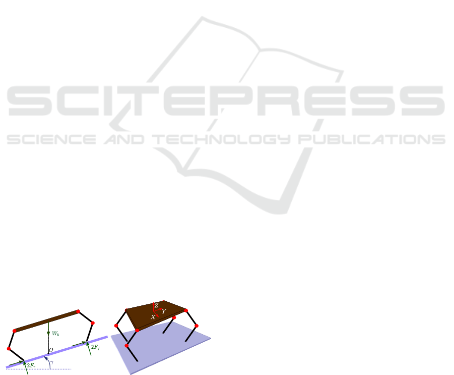
Fig. 2(b). When the robot is positioned on a
horizontal plane, i.e. the surface slope γ = 0, the main
body mass is equally distributed between the four
legs. However, when the robot stand on an inclined
surface with a slope of γ, as shown in Fig. 2(a), the
ground reaction force applied on rear legs F
r
will
be larger than that on front legs F
f
for typical slope
angles 0 ≤γ ≤30
◦
. The rear leg gravity compensation
torque is thus used for the torque capacity evaluations.
3.3 Responsive Motion Index: Dynamic
Manipulability Polytope
For a given scenario in which the robot is subject to
external disturbances, the balance recovery requires
the placement of foot to right place using various
techniques (Pratt and Tedrake, 2006). The responsive
motions of the leg therefore plays a significant role
in balancing of it, as well as in dynamic motions
of the robot. In order to evaluate the agility of
the robot in execution of such motions, the dynamic
manipulability concept is exploited. According to the
definition of the dynamic manipulability, proposed
and elaborated in (Yoshikawa, 1985), this index is
described on the basis of the relation between the
joint driving torque and the end-effector acceleration,
and it represents the robot capability of producing
(a) (b)
Figure 2: Schematics of the quadrupedal robot to be
discussed in this work, without demonstrating the first joint
of the leg (hip yaw/roll).
arbitrary accelerations at the end-effector. To this
end, the dynamic manipulability polytope (DMP)
is exploited in this work to account for the exact
acceleration boundaries of the leg in task space, so
that the dynamic capability of legs in generating
instantaneous responsive motions can be precisely
illustrated. Since the main leg movement required for
the balance recovery of the robot should be carried out
within the plane in parallel to the ground, the dynamic
manipulability evolution in this plane will mostly be
focused, although the variation of this criterion in
vertical axis will also be evaluated.
To define the DMP, the joint torque polytope
defining 2n bounds are expressed as follows
|τ
m
| ≤ τ
max
(4)
where τ
max
is the vector of maximum joint torques,
and |.| symbolizes the absolute value operator acting
on the components of the vector.
The DMP can therefore be derived by mapping
the vertices of the joint torque polytope. As it was
studied in (Yoshikawa, 1985; Chiacchio et al., 1997),
the mapping relation is extracted from (3) and the
second time derivative of (1) when assuming the robot
is standing still. It can therefore be expressed by
τ
m
= M(q)J
−1
(q) ¨p + g(q). (5)
It should be noted that as the mapping relation
is linear and the joint torque polytope is convex,
the dynamic manipulability will hold the convex
property. By mapping the 2
n
vertices of the joint
torque polytope, the vertices required for constructing
the DMP is extracted, as shown in Fig. 3. At any given
configuration, the DMP can therefore be computed
from the 2n equations as follows
|M(q)J
−1
(q) ¨p + g(q)| ≤ τ
max
. (6)
While the computation of DMP vertices for a system
with small number of degrees of freedom (DOFs)
can be done manually, for systems with large number
of DOFs, as well as for cases with high number
of iterations such as this work, when employing
Matlab
r
software, all mapped vertices can found
using the “lcon2vert” function, when the above-said
inequality (6) is expressed by A
a
¨p ≤ b
a
with
A
a
=
M(q)J
−1
(q)
−M(q)J
−1
(q)
, b
a
=
τ
max
−g(q)
τ
max
+ g(q)
. (7)
The DMP effective vertices can accordingly be
extracted and sorted by means of the “convhull”
function that also gives the area and the volume of
the polytope in 2D and 3D space, respectively. The
minimum distance from a given point and the 2D/3D,
to be used for further computations, can then be
Evaluation of Hip Kinematics Influence on the Performance of a Quadrupedal Robot Leg
207
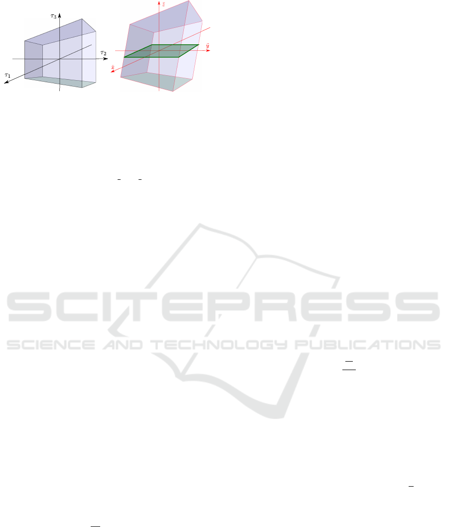
(a) Joint torque polytope (b) DMP
Figure 3: A sample representation of the joint torque
polytope of a 3-DOF robot in a given configuration, and
the corresponding dynamic manipulability polytope for the
aforementioned task space definition, with its coincidence
with the horizontal plane.
acquired by means of the “p poly dist” function. In
this work, the task space position vector is defined by
p = [x, y, z]
T
, and three indexes are defined as follows:
• The area of the DMP coincidence with the
horizontal plane xy; describing a criterion for
overall acceleration in this plane: A
xy
,
• The ratio of the maximum to minimum
acceleration in the horizontal plane xy; subject
to spatial translation of the DMP due to the
gravitational torque; expressing the isotropy of
acceleration in this plane: α
xy
,
• The ratio of the DMP volume to the area A
xy
;
representing a measure for the acceleration along
the vertical axis z: a
z
.
3.4 Slippage Condition Index: Force
Polytope
While the prior index focused on the free motion of
the leg, this index evaluates the leg performance when
applying external force on the end-effector due to the
contact with ground. As the generation of thrust force
on the robot requires the leg end-effector to avoid
slipping on the ground, the third criterion studies the
slippage condition of the leg. The necessary and
sufficient requirement for preventing an object from
slipping on a surface is to apply an adequately large
normal force that satisfies
F
t
F
n
≤ µ
s
, (8)
where F
t
and F
n
represent the tangential and normal
forces, respectively, and µ
s
is the static friction
coefficient of the contact surface.
It is therefore suitable to design the robot leg in
such a way that the highest ratio of normal force to
tangential force on the end-effector can be achieved,
and the locomotion on a wider frictional range for
ground surfaces can be feasible. To achieve this, and
considering the higher accuracy obtained from force
polytope when compared to that from force ellipsoid,
the evolution of the normal force to tangential force
ratio is studied by means of force polytope. Based
on the actuator torque limits (4) presenting the joint
torque polytope, according to (Chiacchio et al., 1997),
the force polytope can be found when the joint
torque to the end-effector force mapping is applied
as follows
τ
m
= J
T
F
ext
. (9)
The force polytope can therefore be computed
by implementing the same procedure as the DMP.
By applying the torque limit (4) on the above-said
torque-force mapping (9), the force polytope vertices
are extracted from A
f
F
ext
≤ b
f
with
A
f
=
J
T
(q)
−J
T
(q)
, b
f
=
τ
max
τ
max
, (10)
while b
f
is replaced by b
a
when the gravitational
translation of the polytope is taken into account.
As the robot body is assumed to be placed in
parallel with the ground, the tangential element F
t
is the external force in the horizontal plane, while
the normal element F
n
is the force along the vertical
axis. To demonstrate the variation in normal force to
tangential force ratio, the index β is defined based on
the volume of the force polytope V
f
, the area of the
force polytope coincidence with the horizontal plane
A
t
, and the maximum tangential force F
mt
as follows
β =
V
f
A
t
F
mt
. (11)
4 SIMULATION ANALYSIS
In this section, the numerical simulations of two legs
based on the two kinematics arrangements are carried
out. For this comparison, the mass and length of
the leg links attached to the afore-stated joints are
assumed to be as follows: The bar linking the hip
roll/yaw joint to the hip pitch joint is 0.1
√
2 m long,
including 0.1 m offset and 0.1 m normal length, with
a mass of 2 Kg, the link connecting the hip pitch joint
to the knee joint has a length of 0.4 m and a mass of
4.5 Kg, and the last link attached to the knee joint is
0.4 m long with a mass of 3.5 Kg. The body mass is
considered to be 80 Kg. To facilitate the presentation
of results, the simulations are carried out in three
cases when the robot body is positioned at three
heights, and the Cartesian motion of the end-effector
is confined with three half-circles as follows: I) at the
height of 0.3 m, with a half-circle of radius 0.5 m,
ICINCO 2016 - 13th International Conference on Informatics in Control, Automation and Robotics
208
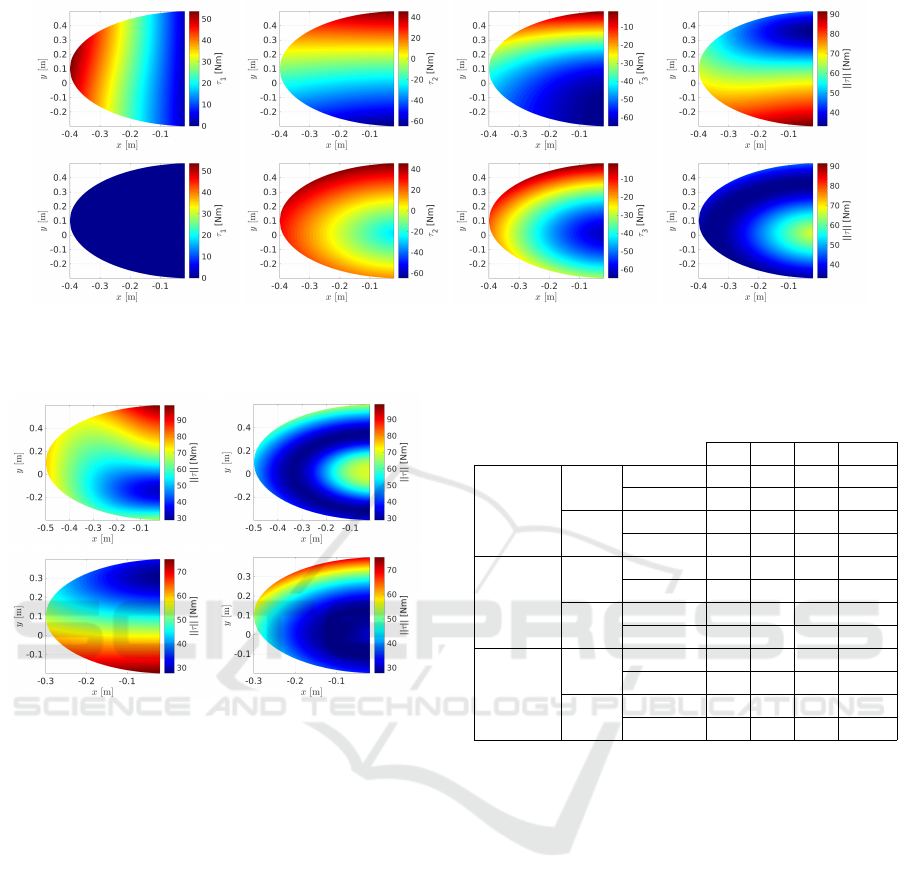
Figure 4: The evolution of gravity compensation torque in xy-plane when the robot is set in different configurations within
the defined workspace II, while standing on a horizontal plane γ = 0, for two kinematics arrangement: The RPP torques at the
first row, and the YPP torques at the bottom.
Figure 5: The evolution of gravity compensation torque in
xy-plane when the robot is set in different configurations
within the defined workspace I and III, while standing on
a horizontal plane γ = 0, for two kinematics arrangement:
The RPP torques on the left side, and the YPP torques on
the right side.
II) at the height of 0.5 m, with a half-circle of radius
0.4 m, III) at the height of 0.7 m, with a half-circle of
radius 0.3 m.
Fig. 4 presents the evolution of the gravity
compensation torque within the workspace defined in
case II, for the both leg arrangements when standing
on a horizontal plane, γ = 0. It illustrates the torque
corresponding to individual joints, as well as the
L
2
−norm of the torque vector. It can be seen that,
when the robot operates on a horizontal plane, the
gravity compensation torques of the hip and knee
pitch joints vary within similar ranges, whereas the
first joints of the two arrangements exhibit differently.
While the hip roll joint demands a considerable
amount of torque, the hip yaw joint needs a negligible
torque. The resulting torque norm of the YPP
arrangement is therefore larger than that of the RPP
arrangement. Such a difference can be also seen in
Table 1: Maximum gravity compensation torque for various
cases (values are in Nm).
τ
1
τ
2
τ
3
||τ ||
Case I
RPP
γ = 0 74 75 65 99
γ = 30
◦
42 73 65 97
YPP
γ = 0 0 63 65 70
γ = 30
◦
36 54 65 70
Case II
RPP
γ = 0 54 65 65 91
γ = 30
◦
34 60 64 88
YPP
γ = 0 0 45 62 67
γ = 30
◦
28 49 65 80
Case III
RPP
γ = 0 40 50 55 75
γ = 30
◦
46 45 51 78
YPP
γ = 0 0 65 32 70
γ = 30
◦
28 56 56 68
the results corresponding to the workspaces defined
in case I and III, reported in Fig. 5 (As for the cases
I and III, for the sake of brevity, only the norm
of the torque vector is reported here). However,
when the robot stands on an inclined surface with a
slope of γ = 30
◦
, see Figs. 6 and 7, the difference
between the maximum torque required for the first
joints significantly decrease. Nevertheless, the torque
threshold associated with the first hip joint of the
YPP arrangement, as well as the torque vector norm,
remains lower than that of the RPP arrangement.
The maximum torque value corresponding to the
different cases are reported in Table 1, demonstrating
lower joint torques for the spider-like leg (YPP
arrangement), as compared to the mammal-like leg
(RPP arrangement). Based on these values, the torque
limit of joints are set to τ
max
= (75, 75, 65) Nm for the
further manipulability analysis.
The evolution of the DMP indexes within the
workspace cases I and III are illustrated in Figs. 8
and 9, respectively. It can be observed from
Fig. 8 that, when the robot body is relatively close
Evaluation of Hip Kinematics Influence on the Performance of a Quadrupedal Robot Leg
209
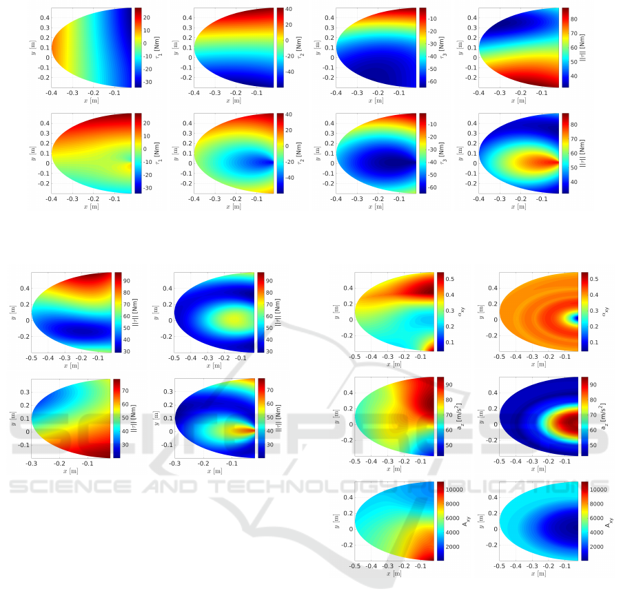
Figure 6: The evolution of gravity compensation torque in xy-plane when the robot is set in different configurations within
the defined workspace II, while standing on an inclined plane γ = 30
◦
, for two kinematics arrangement: The RPP torques at
the first row, and the YPP torques at the bottom.
Figure 7: The evolution of gravity compensation torque in
xy-plane when the robot is set in different configurations
within the defined workspaces I and III, while standing on
an inclined plane γ = 30
◦
, for two kinematics arrangement:
The RPP torques on the left side, and the YPP torques on
the right side.
to the ground, the spider-like leg can possess a
higher level of dynamic manipulability isotropy than
the mammal-like leg; however, in terms of the
DMP magnitude in xy-plane, presented by A
xy
, the
spider-like leg cannot show a better performance than
the mammal-like leg. On the other hand, when
the robot body is set to be in a higher distance
from the ground, i.e. the case III as depicted in
Fig. 9, the mammal-like leg exhibits higher dynamic
manipulability isotropy with lower magnitude A
xy
,
as compared to the spider-like leg. Regarding
the dynamic manipulability along the vertical axis,
represented by a
z
, the mammal-like leg provides
larger end-effector accelerations than the other leg
arrangement in a majority of configurations.
The evaluation of the slippage condition index β
for the two leg kinematics arrangements is illustrated
in Fig. 10. It can be seen that when the robot
Figure 8: The evolution of the DMP indexes in xy-plane
when the robot is set in different configurations within the
defined workspace I, for two kinematics arrangement: The
RPP torques on the left side, and the YPP torques on the
right side.
body is not positioned close to the ground (case
III), the mammal-like leg (RPP arrangement) allows
locomotion on more slippery surfaces, as compared to
the spider-like leg (YPP arrangement). However, the
spider-like leg can render motions on more slippery
surfaces when the robot is configured to hold its
body close to the ground (case I), although it is not
valid everywhere in the defined workspace. When
the robot body is set in a position between the
two above-said cases (case II), the two RPP and
YPP arrangements exhibit similar performances when
the leg end-effector is not radially close to the hip
joint, while the mammal-like leg may possess better
ICINCO 2016 - 13th International Conference on Informatics in Control, Automation and Robotics
210
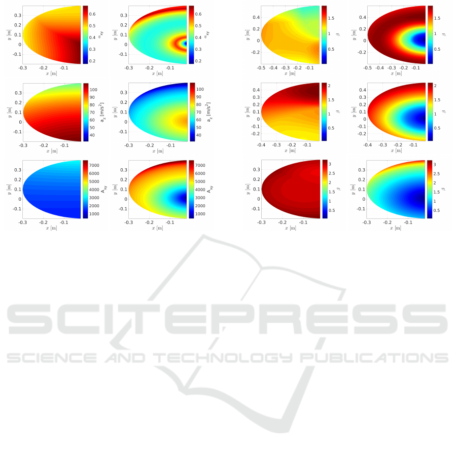
Figure 9: The evolution of the DMP indexes in xy-plane
when the robot is set in different configurations within the
defined workspace III, for two kinematics arrangement: The
RPP torques on the left side, and the YPP torques on the
right side.
slippage avoidance capacity when the leg end-effector
radially approaches the first joint.
5 CONCLUSIONS
This work presented a comparison study for
the leg kinematics arrangement of a quadrupedal
robot, on the basis of two conventional leg
configurations inspired by the skeleton of mammals
and spiders/insects. The statics and dynamics
performances of the two arrangements are evaluated
by defining some criteria including the minimum
torque capacity of joints, the responsive/reactive
motion of legs, and the slippage avoidance condition.
To this end, a set of indexes are defined based
on the gravity compensation torque of joints, the
dynamic manipulability polytope and the force
manipulability polytope. Eventually, the simulation
results describing the evolution of the performance
indexes within a set of workspaces are illustrated.
The results revealed the lower torque requirement
of the spider-like leg as compared to the mammal-like
leg, resulting from the perpendicularity of its first
joint axis to the ground. It was also seen that
the mammal-like leg benefits from higher dynamic
manipulability isotropy when the leg is nearly straight
and the robot body is close to its maximum distance
from the ground. In such a posture, the mammal-like
Figure 10: The evolution of the slippage avoidance index in
xy-plane when the robot is set in different configurations
within the defined workspace I, II and III, presented at
the first, second and third row, respectively; while the two
kinematics arrangement RPP and YPP are shown on the left
and right sides.
leg can also handle slippery surface better than the
spider-like leg. On the other hand, the spider-like leg
can possess larger dynamic manipulability isotropy,
and avoid slippage on more slippery surfaces, when
the robot body is positioned close to ground. The
mammal-like legs can therefore be selected when
straight leg dynamic motions are desired, while the
spider-like legs may be chosen if the execution of
high power tasks demanding large support polygon
and close-to-ground centre of mass is needed.
Future work of the authors may analyse the leg
performance when the passive/active impedance of
joints is taken into account (Laffranchi et al., 2014;
Kashiri et al., 2014; Spyrakos-Papastavridis et al.,
2015).
ACKNOWLEDGEMENTS
This project has received funding from the European
Union’s Horizon 2020 research and innovation
programme under grant agreement Centauro No
644839 (ICT-23-2014 Robotics).
Evaluation of Hip Kinematics Influence on the Performance of a Quadrupedal Robot Leg
211

REFERENCES
Bagheri, M., Ajoudani, A., Lee, J., Caldwell, D. G.,
and Tsagarakis, N. G. (2015). Kinematic Analysis
and Design Considerations for Optimal Base Frame
Arrangement of Humanoid Shoulders. In IEEE Int.
Conf. Robot. Autom., pages 2710–2715, Seattle.
Belter, D., Skrzypczy
´
nski, P., Walas, K., and Wlodkowic,
D. (2015). Affordable Multi-legged Robots for
Research and STEM Education: A Case Study of
Design and Technological Aspects. In Prog. Autom.
Robot. Meas. Tech., pages 23–34. Springer.
Caldwell, D. G., Tsagarakis, N., and Semini, C.
(2014). Mechanism and Structures: Humanoids
and Quadrupeds. In Bioinspired Approaches for
Human-Centric Technologies, pages 133–153.
Chen, J. J., Peattie, A. M., Autumn, K., and Full, R. J.
(2006). Differential leg function in a sprawled-posture
quadrupedal trotter. J. Exp. Biol., 209(2):249–259.
Chen, X., Sun, Y., Huang, Q., Jia, W., and Pu, H.
(2008). Development of Multi-Legged Walking
Robot Using Reconfigurable Modular Design and
Biomimetic Control Architecture. J. Syst. Des. Dyn.,
2(1):401–412.
Chiacchio, P., BouffardVercelli, Y., and Pierrot, F. (1997).
Force polytope and force ellipsoid for redundant
manipulators. J. Robot. Syst., 14(8):613–620.
Corke, P. (2011). Robotics, Vision and Control:
Fundamental Algorithms in MATLAB. Springer
Science & Business Media.
Gasparetto, A., Vidoni, R., and Seidl, T. (2008).
Kinematic study of the spider system in a biomimetic
perspective. In IEEE/RSJ Int. Conf. Intell. Robot.
Syst., pages 3077–3082. IEEE.
Ho, T., Choi, S., and Lee, S. (2007). Development
of a biomimetic quadruped robot. J. Bionic Eng.,
4(4):193–199.
Hutter, M., Gehring, C., Bloesch, M., Hoepflinger, M. A.,
Remy, C. D., and Siegwart, R. (2012). StarlETH: A
compliant quadrupedal robot for fast, efficient, and
versatile locomotion. In 15th Int. Conf. Climbing
Walk. Robot. 2012, number EPFL-CONF-181042.
Kang, T., Kim, H., Son, T., and Choi, H. (2003).
Design of quadruped walking and climbing robot. In
IEEE/RSJ Int. Conf. Intell. Robot. Syst., volume 1,
pages 619–624. IEEE.
Kar, D. C. (2003). Design of statically stable walking robot:
a review. J. Robot. Syst., 20(11):671–686.
Kashiri, N., Tsagarakis, N. G., Van Damme, M.,
Vanderborght, B., and Caldwell, D. G. (2014).
Enhanced Physical Interaction Performance for
Compliant Joint Manipulators using Proxy-based
Sliding Mode Control. In Int. Conf. Informatics
Control. Autom. Robot., pages 175–183, Vienna.
Kato, K. and Hirose, S. (2001). Development of
the quadruped walking robot, TITAN-IXmechanical
design concept and application for the humanitarian
de-mining robot. Adv. Robot., 15(2):191–204.
Laffranchi, M., Chen, L., Kashiri, N., Lee, J., Tsagarakis,
N. G., and Caldwell, D. G. (2014). Development and
control of a series elastic actuator equipped with a
semi active friction damper for human friendly robots.
Rob. Auton. Syst., 62(12):1827–1836.
Negrello, F., Garabini, M., Catalano, M. G., Kryczka, P.,
Choi, W., Caldwell, D. G., Bicchi, A., and Tsagarakis,
N. G. (2016). WALK-MAN Humanoid Lower
body Design Optimization for Enhanced Physical
Performance. In IEEE Int. Conf. Robot. Autom.,
Stockholm.
Pratt, J. E. and Tedrake, R. (2006). Velocity-based stability
margins for fast bipedal walking. In Fast Motions
Biomech. Robot., pages 299–324. Springer.
Raibert, M., Blankespoor, K., Nelson, G., Playter, R.,
and Team, T. B. (2008). Bigdog, the rough-terrain
quadruped robot. In Proc. 17th World Congr.,
volume 17, pages 10822–10825.
Roennau, A., Heppner, G., Pfozter, L., and Dillman, R.
(2013). Lauron V: Optimized leg configuration for the
design of a bio-inspired walking robot. In Proc. 16th
Int. Conf. Climbing Walk. Robot. Support Technol.
Mob. Mach., volume 1417.
Semini, C., Tsagarakis, N. G., Guglielmino, E., Focchi, M.,
Cannella, F., and Caldwell, D. G. (2011). Design
of HyQa hydraulically and electrically actuated
quadruped robot. Proc. Inst. Mech. Eng. Part I J. Syst.
Control Eng., page 0959651811402275.
Seok, S., Wang, A., Chuah, M. Y., Otten, D., Lang, J.,
and Kim, S. (2013). Design principles for highly
efficient quadrupeds and implementation on the MIT
Cheetah robot. In IEEE Int. Conf. Robot. Autom.,
pages 3307–3312. IEEE.
Shkolnik, A., Levashov, M., Manchester, I. R., and
Tedrake, R. (2010). Bounding on rough terrain
with the LittleDog robot. Int. J. Rob. Res., page
0278364910388315.
Siciliano, B., Sciavicco, L., Villani, L., and Oriolo, G.
(2009). Robotics: Modelling, Planning and Control.
Springer Science & Business Media.
Spr
¨
owitz, A., Tuleu, A., Vespignani, M., Ajallooeian, M.,
Badri, E., and Ijspeert, A. J. (2013). Towards dynamic
trot gait locomotion: Design, control, and experiments
with Cheetah-cub, a compliant quadruped robot. Int.
J. Rob. Res., 32(8):932–950.
Spyrakos-Papastavridis, E., Kashiri, N., Lee, J., Tsagarakis,
N. G., and Caldwell, D. G. (2015). Online impedance
parameter tuning for compliant biped balancing. In
IEEE-RAS International Conference on Humanoid
Robots, pages 210–216.
Xie, H., Zhang, Z., Shang, J., and Luo, Z. (2014).
Mechanical Design of A Modular Quadruped
Robot-XDog. In Int. Conf. Mechatronics, Electron.
Ind. Control Eng., pages 1074–1078.
Yoshikawa, T. (1985). Dynamic manipulability of robot
manipulators. In IEEE Int. Conf. Robot. Autom.,
volume 2, pages 1033–1038. IEEE.
Zielinska, T. (2013). Design Issues and Robots Autonomy.
In New Trends Mech. Mach. Sci., pages 691–699.
Zielinska, T. and Heng, J. (2003). Mechanical design
of multifunctional quadruped. Mech. Mach. Theory,
38(5):463–478.
ICINCO 2016 - 13th International Conference on Informatics in Control, Automation and Robotics
212
