
Model based Detection and 3D Localization of Planar Objects for
Industrial Setups
Basak Sakcak, Luca Bascetta and Gianni Ferretti
Dipartimento di Elettronica Informazione e Bioingegneria, Politecnico di Milano,
Piazza L. da Vinci, 32-20133 Milano, Italy
Keywords:
Model based Object Recognition, Pose Estimation, Chamfer Matching.
Abstract:
In this work we present a method to detect and estimate the three-dimensional pose of planar and textureless
objects placed randomly on a conveyor belt or inside a bin. The method is based on analysis of single 2D
images acquired by a standard camera. The algorithm exploits a template matching method to recognize the
objects. A set of pose hypotheses are then refined and, based on a gradient orientation scoring, the best object
to be manipulated is selected. The method is flexible and can be used with different objects without changing
parameters since it exploits a CAD model as input for template generation. We validated the method using
synthetic images. An experimental setup has been also designed using a fixed standard camera to localize
planar metal objects in various scenarios.
1 INTRODUCTION
Recent improvements in robotic manipulation and vi-
sion systems triggered the interest in using visual
systems for manipulation of objects in industrial en-
vironments, instead of ad-hoc mechanical solutions.
Such problem requires identifying and locating the
searched object in a scene of randomly placed parts.
Despite being studied extensively, recognition and lo-
calization still remains challenging for industrial se-
tups. One of the main challenge is related to the
presence of dimly or unevenly lit environments, in
which the acquired images have high contrast varia-
tions making it difficult to process them. Most of the
time the parts are randomly scattered in a bin or im-
properly stacked, hence it is necessary for the vision
system to cope with clutter and occlusions. Another
challenge is caused by the properties of the objects to
be recognized and located. They generally have sim-
ple shapes with no texture information, such that most
of the recognition algorithms that account for salient
features regarding complex shapes, surface normals
or texture information would fail, leaving the contour
of the object being the most reliable feature. With
the increased availability of 3D vision systems, there
is a trend in using 3D data instead of traditional 2D
images. 3D vision systems give the possibility to di-
rectly register the part to the received point cloud and
they do not suffer from viewpoint changes or projec-
tion errors, which are crucial problems for conven-
tional cameras. However, 3D sensors still have im-
portant limitations; they are not robust with respect to
surface reflectance and most of the time they require
expensive equipment to detect thin objects, which
also limits the field of view. Therefore considering
also their ease of availability and cost effectiveness
2D cameras are still popular.
In this work we present a framework for model
based detecting and localizing multiple objects using
a single image acquired by a monocamera, and for
finding the best match representing the best object to
be manipulated. The general pipeline of the algorithm
is provided in Figure 1, where a sequence of steps
are proposed to recognize and localize the best ob-
ject to be manipulated. First step is the recognition
of the objects in the scene. This part is based on the
template matching approach proposed by Liu et. al.
(2012), rooted from the traditional chamfer matching.
We have picked a template matching method that ex-
ploits the contour considering the shape property of
the objects to be recognized. The gist of the algo-
rithm is to find the best parameters that align the tem-
plate within the image with respect to a dissimilarity
cost based on chamfer distance augmented by a term
accounting for the orientation mismatch. Line based
representation of the detected edges is used as well
for computing the integral of the distance transform
along quantized directions to improve the speed and
360
Sakcak, B., Bascetta, L. and Ferretti, G.
Model based Detection and 3D Localization of Planar Objects for Industrial Setups.
DOI: 10.5220/0005982503600367
In Proceedings of the 13th International Conference on Informatics in Control, Automation and Robotics (ICINCO 2016) - Volume 2, pages 360-367
ISBN: 978-989-758-198-4
Copyright
c
2016 by SCITEPRESS – Science and Technology Publications, Lda. All rights reserved
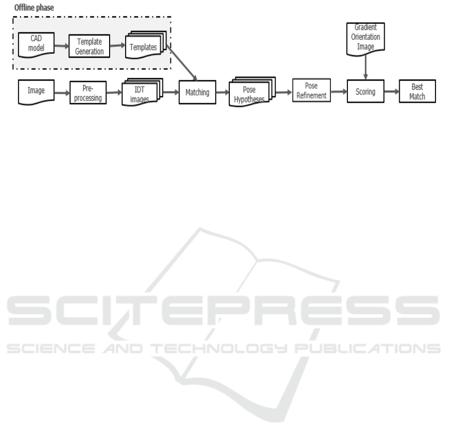
Figure 1: Pipeline of the recognition and localization.
reduce the complexity of the search. The recognition
procedure provides a set of coarse pose hypotheses.
A pose refinement method, that takes into consider-
ation also the missing edges and occlusions, allows
then to precisely localize multiple objects of the same
kind. We also augmented the framework with a scor-
ing part based on the gradient orientation computed
on the query image that allows us to pick the best ob-
ject to be manipulated i.e. the topmost one and dis-
card false matches.
1.1 Related Works
Standard cameras and 2D image analysis have been
studied for various applications, however, matching
the detected object in an image with its 3D model is
still challenging. For that purpose one popular ap-
proach is to use invariant feature descriptors such as
SIFT (Lowe, 2004), SURF (Bay et al., 2006), Scene-
Tensor (S
¨
oderberg et al., 2005) to find the correspon-
dences between the acquired image and the 3D model.
Another approach is to match the retrieved image with
a database of images trained from the object. How-
ever, this approach is computationally inefficient and
also prone to errors due to appearance changes. To
overcome these issues, a hierarchical view-based ap-
proach is proposed in (Ulrich et al., 2009), adopt-
ing the descriptor that uses the difference between
the gradient orientations computed in the image and
the orientation attributed to the edge (Steger, 2002),
which is robust to appearance changes and occlusions.
Another method improves the usage of this descrip-
tor for small translations and rotations by spreading
the gradient orientations and computing offline re-
sponse maps for a highly optimized matching pro-
cedure (Hinterstoisser et al., 2012). Despite being
one of the earliest shape matching algorithms Cham-
fer Matching (Barrow et al., 1977) still remains pop-
ular. This approach relies on the minimization of
the distance between two sets of edge points, which
can be speeded up using Distance Transform. There
are several variants proposed in the literature that ac-
count also for the edge orientation in the computa-
tion of the cost together with the traditional cham-
fer distance (Shotton et al., 2008), (Liu et al., 2012).
Other shape matching methods, such as voting based
approaches, utilize Hough Transform or a Hough
like voting scheme. Cozar’s group exploits Gen-
eral Hough Transform to locate 3D arbitrary planar
shapes, where the parameter detection is uncoupled
by the usage of invariants (C
´
ozar et al., 2001). Pretto
et al. (2003) presented a novel cost function based
on dynamically adapted gradient magnitude to be im-
plemented in a Hough-like voting approach. In the
recent years, with 3D sensors becoming more cost
effective, there has been an increased interest in re-
search on using directly the 3D data for localization.
Nieuwenhuisen et al. (2013) proposed a method to
detect an object using its primitives. They used the
data obtained by a Microsoft Kinect RGB-D camera
attached to the pan-tilt head of an anthropomorphic
robot. To overcome the limited field-of-view, mul-
tiple scans are overlapped using the ICP algorithm
(Zhang, 1994). Based on the algorithm initially pro-
posed in (Schnabel et al., 2008) an annotated graph is
formed where the nodes correspond to simple shapes
(spheres, cylinders, planes) both for the model and the
scene. These two graphs are then queried for match-
ing. Papazov’s group presented a method based on
a robust geometric descriptor, hashing technique and
a RANSAC-like sampling strategy (Papazov et al.,
2012). In that approach the object model is prepared
as oriented point pairs and its geometric descriptors
are stored in a hash table. The retrieved point pairs are
used to compute the same descriptor, which is then
used as a key to access a hash table. Finally, simi-
lar points give out the transformation that maps the
object to the scene. This solution is accepted or re-
jected based on a RANSAC-based acceptance func-
tion. Voting approach is employed also for meth-
ods based on 3D data. A novel technique is intro-
duced to create a global model description and match
it locally, allowing to use sparser point clouds (Drost
et al., 2010). The global model description is carried
Model based Detection and 3D Localization of Planar Objects for Industrial Setups
361

out offline and it represents a mapping from the point
pair feature space to the model. A Hough-like voting
scheme is used on a geometric feature descriptor of
pairs of oriented point pairs. A subset of hypothesis
are then chosen using a nearest neighbour clustering
algorithm. The final pose refinement is sustained by
using the ICP algorithm. Another approach is to en-
hance this method by various pre and post process-
ings, e.g. (Skotheim et al., 2012) and (Choi et al.,
2012) introduced new point pair descriptors.
2 OBJECT RECOGNITION
For the object recognition step, we adopt a template
matching approach that recognizes the object in the
scene by searching for the parameters that align the
template while minimizing a cost including the cham-
fer distance and a direction mismatch called Direc-
tional Chamfer Matching (Liu et al., 2012). At the
end of the recognition part we obtain a set of coarse
pose hypotheses with minimum costs corresponding
to the 3D poses of the searched objects in the scene.
In this section we will explain template generation
and line segment based representation of the edges.
A brief description of the shape matching algorithm
will be given as well.
2.1 Template Generation
Assume that a virtual camera is located at the origin
of a world coordinate frame while aligning the cam-
era optical axis with the z-axis, the rotation about this
axis and the translations in the plane orthogonal to
the optical axis are defined as in-plane parameters.
During matching, the algorithm takes into account in-
plane rotation (θ
z
) and translations (t
x
,t
y
). However,
rotations about the remaining axes (θ
x
and θ
y
) result
in different object contours in two-dimensional image
plane. In this work, we particularly focused on de-
tection of planar objects. For this case, the shape de-
formation caused by the out-of-plane rotations is rel-
atively small to be handled by the chamfer matching
algorithm. Thus, we used a single reference template,
to be searched in the acquired image. Nonetheless
the algorithm is flexible to function also with multi-
ple templates.
Template is generated automatically during the
off-line phase. For that purpose we first obtain a set
of n 3D points defined as
˜
U =
{
˜u
i
}
n
i=1
and their di-
rections in the object reference frame. The points are
generated by rasterization of a 3D CAD model with a
step selected considering the size of the object. The
direction of each point is obtained as the local direc-
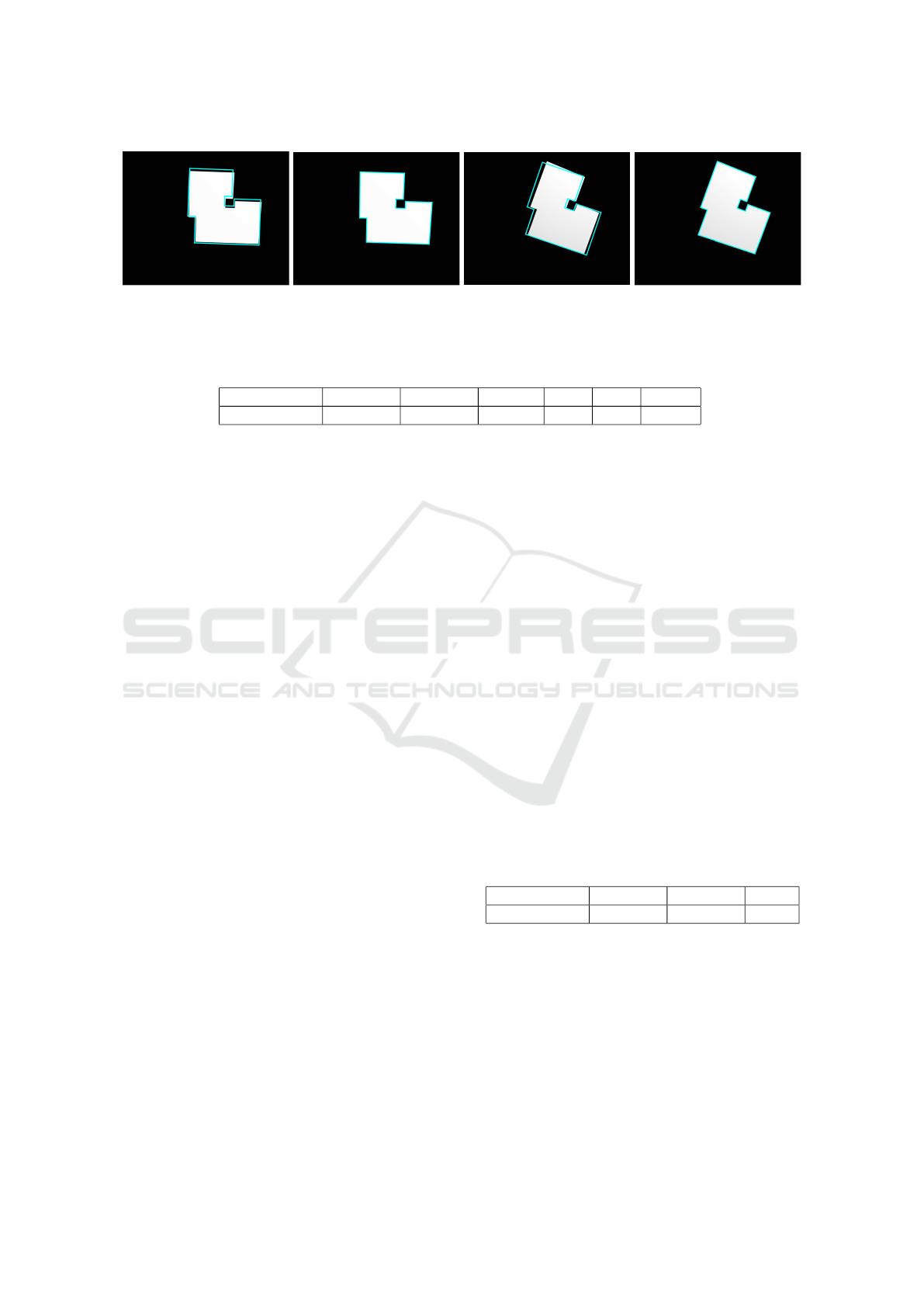
(a) (b)
Figure 2: (a) Query image. (b) Line based representation of
the edges.
tion of the edge line at which the point belongs. Con-
sidering a transformation matrix T
m
that expresses
the pose of the object model in the camera coordinate
frame exploiting the pose p = [
t
x
t
y
t
z
θ
x
θ
y
θ
z
]
T
T
m
(p) =
R
m
t
m
0 1
(1)
a template is generated by projecting the points de-
fined in the object frame to the image frame using the
following equation
u
i
= PT
m
(p) ˜u
i
(2)
where P is the 3x4 projection matrix obtained by the
camera calibration, and T
m
is the pose of the 3D
model with respect to the camera frame. Points are
represented in homogeneous coordinates, and since
the objects have a planar shape all 3D points of the
template in the object frame have z = 0. Initial pose
p
0
consists of only an assumption for the distance of
the objects from the camera, hence p
0
= [
0 0 t
z
0 0 0
]
T
.
2.2 Representation of Edge Points
The edge map of a query image is represented as com-
posed of line segments instead of a binary image. This
provides a minimal representation since all the edge
pixels along a line segment can be represented by us-
ing only two points. Furthermore, direction informa-
tion of each edge point can be easily computed using
a line based representation. Considering industrial se-
tups and the related objects, traditional edge detection
methods tend to provide poor results due to low gra-
dient values. In order to increase the detection rate we
used a state of the art edge detection algorithm (Fig-
ure 2) called Line Segment Detector (von Gioi et al.,
2008). As a result we obtain a set of line segments and
their directions. For the computation of directional
chamfer matching cost and the related cost maps, di-
rections are quantized into a number q of orientation
channels that equally spans [0, π). We used q = 60
orientation channels.
ICINCO 2016 - 13th International Conference on Informatics in Control, Automation and Robotics
362

2.3 Directional Chamfer Matching
Chamfer Matching (Barrow et al., 1977) is a contour
based technique to detect a template in an image and
to find the best alignment parameters. Two point sets
can be defined as U =
{
u
i
}
n
i=1
being the edge pixels
of the template edge map and V =
v
j
|V |
j=1
being the
edge pixels of the query image edge map, where n and
|V | represent the total number of the edge points in
each set. Then, the chamfer distance which expresses
the dissimilarity between these two point sets can be
defined as the average of the distances between the
edge pixels u
i
∈ U and their nearest pixel in V
d
CM
(U,V ) =
1
n
∑
u
i
∈U
min
v
j
∈V
|u
i
− v
j
| (3)
For efficiency, the chamfer distance between two
point sets can be computed using the distance trans-
form (DT). DT inputs a binary edge map and assigns
to each pixel x the minimum distance to the nearest
edge point
DT
V
(x) = min
v
j
∈V
|x − v
j
| (4)
Using the Generalized Distance Transform (Felzen-
szwalb and Huttenlocher, 2004), the DT of an im-
age can be computed in linear time by dynamic pro-
gramming. As a result, the problem of computing the
chamfer distance between the template points and the
image edge points is transformed into a look-up table
and is defined as;
d
CM
(U,V ) =
1
n
∑
u
i
∈U
DT
V
(u
i
) (5)
Directional chamfer matching (DCM) makes use of
the direction term attributed to each pixel thanks to a
line based representation. The DCM cost is given as
d
DCM
(U,V ) =
1
n
∑
u
i
∈U
min
v
j
∈V
(
u
i
− v
j
+ λ
φ(u
i
) − φ(v
j
)
) (6)
where λ is the weight for the direction term and
φ(u
i
), φ(v
j
) represent the orientations of the template
and edge points, respectively. In order to reduce the
complexity of the problem of finding the in-plane pa-
rameters that minimize this cost, a three-dimensional
distance transform (DT 3
V
) is used to compute the
matching cost in linear time. DT 3
V
jointly computes
the minimum distance of each pixel to an edge point
in terms of location and orientation. For each pixel
and direction channel, DT 3
V
cost is expressed as
DT 3
V
(x, φ(x)) =
min
ˆ
φ
i
∈Φ
DT
V (
ˆ
φ
i
)
+ λ
ˆ
φ(x) −
ˆ
φ
i
π
(7)
where
ˆ
φ(x) and
ˆ
φ
i
represent the quantized orientation
assigned to a pixel and the orientation channel of the
cost map the pixel belongs to. In order to compute the
DT 3
V
edges that belong to the same orientation chan-
nel are grouped in the same binary edge image and a
distance transform is computed for each of them. A
total number of q distance transform images (DT
V (
ˆ
φ
i
)
)
are obtained and using dynamic programming the dif-
ference between the orientation of the edge point that
corresponds to a pixel and the orientation channel is
added to the cost. As a result the directional chamfer
matching cost for a template U is computed as
d
DCM
(U,V ) =
1
n
∑
u
i
∈U
DT 3
V
(u
i
,
ˆ
φ(u
i
)) (8)
Considering all pixels along a line segment belong-
ing to the same orientation channel the cost is easily
computed using the integral distance transform repre-
sentation. Integral distance transform represented as
IDT 3
V
(x,
ˆ
φ
i
) =
∑
x
j
∈[x
0
,x]
DT 3
V
(x
j
,
ˆ
φ
i
) (9)
is achieved by summing the DT 3
V
cost of a specific
orientation channel over the points along that direc-
tion. Taking L
U
= l
[s
i
,e
i
]
, i = 1,. . . , m as the represen-
tation of the line segments defining a template, where
s
i
and e
i
are the start and the end points of the i
th
seg-
ment, the chamfer matching score of each segment is
computed as
d
DCM
(U,V ) =
1
n
∑
l
i
∈L
U
IDT 3
V
(e
i
,
ˆ
φ(l
i
)) − IDT 3
V
(s
i
,
ˆ
φ(l
i
)
(10)
2.4 Matching
Matching is the process of finding the best in-
plane parameters ˆs = (θ,t
x
,t
y
) with the lowest DCM
cost that align the template within the query image.
Searching these parameters individually with a brute-
force approach is computationally inefficient. There-
fore, as proposed by Liu et. al. (2012) the search is
guided by using the longest line segments from the
Model based Detection and 3D Localization of Planar Objects for Industrial Setups
363

corresponding query and template sets. To this intent,
the template is rotated and translated to be aligned
with the query line segment such that the end point
of the template line segment coincides with the query
line segment.
3 POSE REFINEMENT AND BEST
MATCH SELECTION
The coarse pose hypotheses obtained from the recog-
nition part are limited to the out-of plane parameters,
that are used to render the template, and the search
step taken during matching phase. Thus, in order to
precisely estimate the exact three dimensional pose
of the object, a fine refinement step is necessary. Fur-
thermore, we intend to identify the best object to be
manipulated, which we define as the topmost in the
batch. In an ideal case of all possible edges detected
this object would be the one with the lowest DCM
cost, however low contrast regions due to overlapping
textureless objects give rise to image zones with less
detected edge lines, hence resulting in higher scored
regions. One such example is reported in Figure 3,
where the minimum cost pose hypothesis does not
correspond to the topmost object. In order to avoid
this, we exploit the local gradient orientations com-
puted in the query image to perform a scoring step.
3.1 Pose Refinement
First the translation parameters t
x
and t
y
, that are ex-
pressed in image coordinates, are back-projected to
the camera coordinate frame using the camera projec-
tion matrix P. Back-projected translation parameters
and the estimated rotation about the camera axis (θ
z
)
combined with the out-of-plane parameters (θ
x
, θ
y
)
and the initial assumption of distance from the camera
t
z
are used to define the matrix T
m
(p) as in (1), that
represents the coarse pose of the object in the cam-
era coordinate system. We minimize the least squares
projection error to refine the pose estimate. In order
to compute the least squares error a set of correspon-
dences is necessary. To this extent, template points
are projected on the image plane using (2). For each
u
i
projected on the image plane a nearest edge point
v
i
in V is found which minimizes the DCM cost, such
that
argmin
v
i
∈V
u
i
− v
j
+ λ
φ(u
i
) − φ(v
j
)
(11)
Considering the missing edges due to low contrast or
objects with partial occlusion, it is not logical to use
(a) (b)
Figure 3: (a) Missing edge lines caused by low contrast. (b)
Hypothesis with the minimum DCM cost which is not the
best match.
all the correspondences as they might cause the op-
timization algorithm to converge to a wrong result.
Hence, we use a thresholding such that only the pairs
that have a DCM cost smaller than a threshold are
used in the refinement process. We use a threshold-
ing based on a factor δ related to the median of the
costs computed for every template point, unless it is
below a certain value µ
base
, such that the cost thresh-
old of accepting a point pair for refinement can be
expressed as
µ =
(
δmedian(d
DCM
), if µ
base
< δmedian(d
DCM
)
µ
base
, otherwise
(12)
As a result 3D-2D point correspondences are es-
tablished as ( ˜u
k
,v
k
), where ˜u
k
is a subset of raster-
ized template points ˜u
i
that have correspondences v
k
within the cost bound defined by the thresholding.
Using these point pairs the least squares projection
error is defined as follows
1
ε(p) =
∑
˜u
k
k
PT
m
(p) ˜u
k
− v
k
k
2
(13)
Error function is then minimized for each hypothesis
using the Levenberg-Marquardt algorithm by finding
at each step a set of point pairs after outliers have been
removed.
3.2 Best Match Selection
Assuming the best object to be manipulated is top-
most object in the batch, it should have all of its edges
visible. Hence, when projected on the image plane
the normals of the direction terms assigned to the
template edge points should coincide with the corre-
sponding local gradient orientations in the query im-
age. A similar measure is also used in (Pretto et al.,
1
For the ease of notation we assume that the projection
of 3D points are already converted into image coordinates
to compute the error.
ICINCO 2016 - 13th International Conference on Informatics in Control, Automation and Robotics
364
(a) (b) (c) (d)
Figure 4: Examples of correct pose estimation in various out-of-plane rotations using single template (a)(c) Coarse pose
estimations (b)(d) Estimated poses after fine registration.
Table 1: Results from the experiments using synthetic images.
Average error t
x
t
y
t
z
θ
x
θ
y
θ
z
<0.5 mm <0.5 mm 1.2 mm 1deg 1deg 0.3deg
2013). As a result the scoring function is defined as
follows
S (U, I
go
) =
∑
u
i
∈U
|
cos(I
go
(x
i
)) − n
o
(u
i
))
|
(14)
where I
go
(x
i
) is the gradient orientation of the pixel
corresponding to the template point u
i
projected on
the image frame using (2). The best matching pose p
∗
is then selected being the one that gives out a transfor-
mation matrix T
∗
m
that projects 3D template points ˜u
i
on the image plane with the highest score S (U, I
go
).
This scoring also allows us to discard falsely recog-
nized and located objects as well. Considering the
best match would have a score equal to 1 we eliminate
all matches that receive a score less than a threshold.
4 EXPERIMENTS AND RESULTS
We conduct experiments both on synthetic and real
images used as two different mediums to verify
the functionality of the recognition and localization
framework.
4.1 Synthetic Data
Synthetic images are used to test the accuracy of the
pose estimation. We used Blender software to ren-
der a set of images of 3D objects. The object is ren-
dered changing out-of-plane and in-plane parameters.
Using the synthetic images we found that the fine re-
finement algorithm is capable of recovering an out-of
plane rotation bounded in ±20
◦
when a single tem-
plate is used. Figure 4 shows two examples of the pro-
jected pose of the template after coarse pose estima-
tion and fine registration, respectively. It is possible
to observe that the shape change due to out-of-plane
rotation of the object is rather small, and a single tem-
plate is sufficient to achieve a precise localization of
the object. As a result, 50 synthetic images are gener-
ated with known poses and the results as the averages
of the errors for translation and rotation are reported
in Table 1.
4.2 Real Images
In order to test the algorithm using real images a
simple experimental set-up was designed (Figure 7).
We used a 1.3 megapixels grey-level CMOS camera
mounted on a fixed frame facing the table where the
work pieces are located, and an ABB IRB 140 robotic
manipulator with a calibration tool attached to the
end effector. Camera intrinsic parameters are com-
puted using the single camera calibrator application
of MATLAB. Camera is then calibrated with respect
to the robot world frame to obtain the transformation
matrix T
cam
base
which maps the points represented in the
camera frame to the robot world frame.
Table 2: Results from real images.
Average error t
x
t
y
t
z
<0.5 mm <0.5 mm 2 mm
The procedure to verify the localization accuracy
of the algorithm in a real world setup starts with ob-
taining the values of the corner points of the query
object in the camera frame using the best match as
shown in Figure 5. These points are then mapped to
the robot world frame using the transformation ma-
trix. The actual values of the corner points are ob-
tained directly in the robot world frame by manu-
ally touching the corners of the object in the jogging
mode using the calibration tool, a probe with a known
Model based Detection and 3D Localization of Planar Objects for Industrial Setups
365
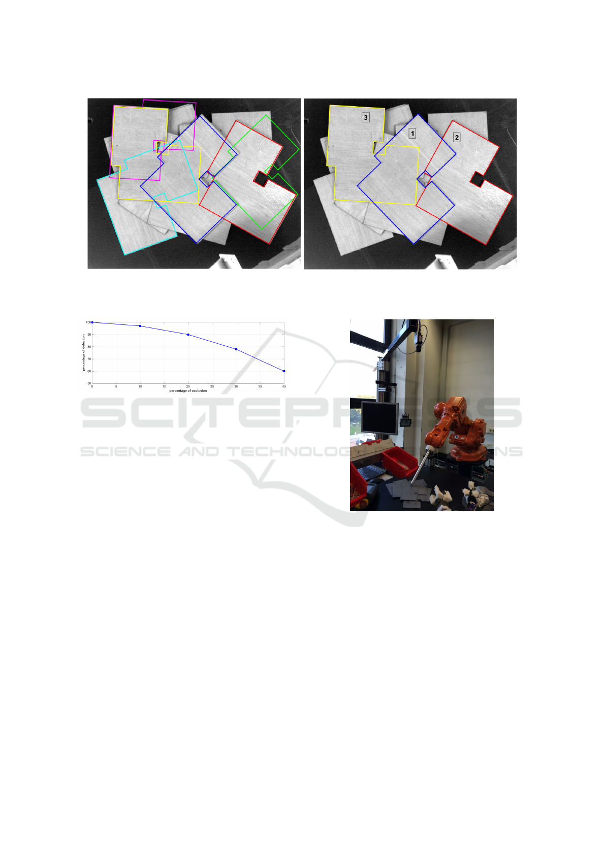
(a) (b)
Figure 5: Final results of the localization on real images a)selected hypotheses before pose refinement b)refined poses and the
selected matches that have sufficient score value, the best match is denoted as ’1’.
Figure 6: Percentage of recognition with respect to percent-
age of occlusion.
length mounted on the robot wrist. These results are
then compared to test the performance of the algo-
rithm. Results in the form of the averages of the er-
rors are reported in Table 2. One can also see that the
hypotheses that have higher scores but falsely recog-
nized or highly occluded are removed after the refine-
ment/scoring step. We have evaluated the localization
of the other hypotheses qualitatively, by projecting the
3D template points on the image plane.
We have also tested the performance of the algo-
rithm when the objects to be detected are occluded.
The occlusion is defined as the amount of area of an
object covered by other objects, the results of the de-
tection rate are reported in Figure 6. The algorithm
performs well in detecting objects with less than %10
of occlusion.
5 CONCLUSIONS
We presented a framework for model based recog-
nition and pose estimation of planar, textureless ob-
jects. The method can be used to avoid rigid mechan-
ical solutions for manipulation and inspection pur-
poses in industrial environments. As the original al-
Figure 7: Experimental setup.
gorithm exploits a special vision system that allows
to detect edges accurately, the single output provides
the best object to be manipulated. However when a
conventional camera is used the resulting best match
might not be the best object to be manipulated, due to
the low contrast regions with less amount of detected
edges. For that reason we have modified the pose re-
finement step, that now allows to recognize and local-
ize multiple objects of the same kind, and augmented
the algorithm with a scoring step based on the gradi-
ent orientation that gives out the best match. With the
proposed approach, we obtained a good best match
recognition rate and localization accuracy that is suit-
able for industrial environments.
ICINCO 2016 - 13th International Conference on Informatics in Control, Automation and Robotics
366

REFERENCES
Barrow, H., Tenenbaum, J., Bolles, R., and Wolf, H. (1977).
Parametric correspondence and chamfer matching:
two new techniques for image matching. In Proceed-
ings of the 5th international joint conference on Arti-
ficial intelligence-Volume 2, pages 659–663. Morgan
Kaufmann Publishers Inc.
Bay, H., Tuytelaars, T., and Van Gool, L. (2006). Surf:
Speeded up robust features. In Computer vision–
ECCV 2006, pages 404–417. Springer.
Choi, C., Taguchi, Y., Tuzel, O., Liu, M.-Y., and Rama-
lingam, S. (2012). Voting-based pose estimation for
robotic assembly using a 3d sensor. In Robotics and
Automation (ICRA), 2012 IEEE International Confer-
ence on, pages 1724–1731. IEEE.
C
´
ozar, J. R., Guil, N., and Zapata, E. L. (2001). Detection
of arbitrary planar shapes with 3d pose. Image and
Vision Computing, 19(14):1057–1070.
Drost, B., Ulrich, M., Navab, N., and Ilic, S. (2010). Model
globally, match locally: Efficient and robust 3d object
recognition. In 2010 IEEE Computer Society Confer-
ence on Computer Vision and Pattern Recognition.
Felzenszwalb, P. and Huttenlocher, D. (2004). Distance
transforms of sampled functions. Technical report,
Cornell University.
Hinterstoisser, S., Cagniart, C., Ilic, S., Sturm, P., Navab,
N., Fua, P., and Lepetit, V. (2012). Gradient re-
sponse maps for real-time detection of textureless ob-
jects. Pattern Analysis and Machine Intelligence,
IEEE Transactions on, 34(5):876–888.
Liu, M.-Y., Tuzel, O., Veeraraghavan, A., Taguchi, Y.,
Marks, T. K., and Chellappa, R. (2012). Fast ob-
ject localization and pose estimation in heavy clutter
for robotic bin picking. The International Journal of
Robotics Research, 31(8):951–973.
Lowe, D. G. (2004). Distinctive image features from scale-
invariant keypoints. International journal of computer
vision, 60(2):91–110.
Papazov, C., Haddadin, S., Parusel, S., Krieger, K., and
Burschka, D. (2012). Rigid 3d geometry matching
for grasping of known objects in cluttered scenes.
The International Journal of Robotics Research, page
0278364911436019.
Pretto, A., Tonello, S., and Menegatti, E. (2013). Flexi-
ble 3d localization of planar objects for industrial bin-
picking with monocamera vision system. In Automa-
tion Science and Engineering (CASE), 2013 IEEE In-
ternational Conference on, pages 168–175. IEEE.
Schnabel, R., Wessel, R., Wahl, R., and Klein, R. (2008).
Shape recognition in 3d point-clouds. In The 16-th
International Conference in Central Europe on Com-
puter Graphics, Visualization and Computer Vision,
volume 8. Citeseer.
Shotton, J., Blake, A., and Cipolla, R. (2008). Mul-
tiscale categorical object recognition using contour
fragments. Pattern Analysis and Machine Intelligence,
IEEE Transactions on, 30(7):1270–1281.
Skotheim, Ø., Lind, M., Ystgaard, P., and Fjerdingen, S. A.
(2012). A flexible 3d object localization system for
industrial part handling. In Intelligent Robots and
Systems (IROS), 2012 IEEE/RSJ International Con-
ference on, pages 3326–3333. IEEE.
S
¨
oderberg, R., Nordberg, K., and Granlund, G. (2005). An
invariant and compact representation for unrestricted
pose estimation. In Pattern Recognition and Image
Analysis, pages 3–10. Springer.
Steger, C. (2002). Occlusion, clutter, and illumination in-
variant object recognition. International Archives of
Photogrammetry Remote Sensing and Spatial Infor-
mation Sciences, 34(3/A):345–350.
Ulrich, M., Wiedemann, C., and Steger, C. (2009). Cad-
based recognition of 3d objects in monocular images.
In ICRA, volume 9, pages 1191–1198.
von Gioi, R. G., Jakubowicz, J., Morel, J.-M., and Randall,
G. (2008). Lsd: A fast line segment detector with a
false detection control. IEEE Transactions on Pattern
Analysis & Machine Intelligence, (4):722–732.
Zhang, Z. (1994). Iterative point matching for registration
of free-form curves and surfaces. International jour-
nal of computer vision, 13(2):119–152.
Model based Detection and 3D Localization of Planar Objects for Industrial Setups
367
