
Fuzzy Control with Friction Compensation for a Pneumatic
Positioning System
Kuo-Ming Chang
1
, Yung-Tien Liu
2
and Sheng-Jung Hsieh
1
1
Department of Mechanical Engineering, National Kaohsiung University of Applied Sciences, 415 Chien-Kung Rd.,
Kaohsiung, Taiwan
2
Department of Mechanical and Automation Engineering, National Kaohsiung First University of Science and Technology,
2 Jhuoyue Rd., Kaohsiung, Taiwan
Keywords: Fuzzy Control, Friction, Position Control, Pneumatic Positioning System.
Abstract: In this paper, a fuzzy control with friction compensation is developed to deal with a nonlinear pneumatic
positioning system characterized with friction, unknown system model, and external disturbance. In order to
enhance the positioning accuracy, a control scheme is designed for compensating the friction effect of the
moving stage. Positioning experiments based on the derived control strategy were performed to show and
validate the proposed control performance. As two experimental examples of positioning results in a total of
30 experimental trials for the stepwise input positioning controls, the positioning accuracy with less than
30nm was verified for both forward and backward actuations with step commands. Hence, the control
scheme provided in this paper that could significantly improve the positioning performance of a traditional
pneumatic positioning system is demonstrated.
1 INTRODUCTION
Pneumatic positioning device is one of the most
important facilities in automation industry with
major applications found in end positions control.
However, due to the nature of the air medium being
compressible and the friction force existing on
sliding surfaces being nonlinear, it is very difficult to
achieve high-precision position control using
pneumatic actuating devices. With the need of
improving the positioning accuracy, many studies
were largely performed in implementing suitable
controllers with different strategies. In order to
improve the positioning performance of pneumatic
positioning systems, many control methods have
been proposed, such as sliding mode control (Paul et
al., 1994; Song and Ishida, 1996; Korondi and
Gyeviki, 2006), observer-based adaptive sliding
mode control (Liu et al., 2013), adaptive multilayer
neural network control (Gross and Rattan, 1998),
fuzzy PWM control (Shih and Ma, 1998), and the
scheme of pneumatic system combined with
piezoelectric actuators (Liu et al., 2004; Chiang et al.,
2005; Liu and Jiang, 2007). In addition, it has been
also reported as effectiveness to compensate the
stick-slip phenomenon by adding a velocity
compensation signal to the servo valve (Pai and
Shin, 2003) and by using a piezoelectric dither (Liu
et al., 2011).
In this paper, a fuzzy control with friction
compensation is proposed to achieve the high
positioning performance for a pneumatic positioning
system. Furthermore, it is proven that the proposed
control scheme can obtain the positioning accuracy
with less than 30nm in an experimental pneumatic
positioning system.
2 PNEUMATIC POSITIONING
SYSTEM
The pneumatic positioning system is schematically
shown in Figure 1 and the photograph of
experimental equipment is shown in Figure 2. A
pneumatic cylinder (Airpel, ø10×12mm) is fixed to
the base. The target object of sliding table with a
dimension of 35×25×35mm rests on the V-grooved
base. The pneumatic cylinder is controlled by a
proportional valve (Festo, MPYE-5-M5-010B). A
12-bit digital-to-analog (D/A) converter is used to
transfer the control command to the proportional
Chang, K-M., Liu, Y-T. and Hsieh, S-J.
Fuzzy Control with Friction Compensation for a Pneumatic Positioning System.
DOI: 10.5220/0005976004710476
In Proceedings of the 13th International Conference on Informatics in Control, Automation and Robotics (ICINCO 2016) - Volume 1, pages 471-476
ISBN: 978-989-758-198-4
Copyright
c
2016 by SCITEPRESS – Science and Technology Publications, Lda. All rights reserved
471
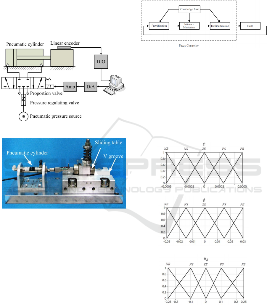
valve (PV) via a power amplifier. A non-contact
type linear encoder (Renishaw, RGH25F2000) with
the resolution of 10 nm is mounted beside the sliding
table and the displacement of sliding table is
measured by the linear encoder through digital
input/output (DIO) ports. To avoid environmental
disturbance, the experimental setup is set on an anti-
vibration air table.
Figure 1: Pneumatic positioning system.
Figure 2: Photograph of the experimental equipment.
3 FUZZY CONTROL WITH
FRICTION COMPENSATION
Due to the factors of air compressibility, the moving
friction, and the external disturbance, the pneumatic
positioning system is usually considered as a kind of
nonlinear time-varying system with dead-zone input
caused by the proportional valve. An exact
mathematical model of pneumatic positioning
system is difficult to be constructed and obtained for
designing a suitable controller specified in terms of a
concise mathematical model. Hence, a fuzzy control
which can provide an effect means of dealing with
the approximate and inexact model of the controlled
system is applied to control the pneumatic
positioning system in this paper. The framework of
fuzzy controller can be composed of four parts,
fuzzification, inference mechanism, defuzzification,
and knowledge base, as shown in Figure 3.
Figure 3: Fuzzy controller in the overall control structure.
Defining a displacement tracking error as
)()()( txtxte
d
(1)
where
)(tx
is the sliding table displacement and
)(tx
d
is the reference command. In this paper, the
fuzzy controller is built by considering the tracking
error
)(te
and its variation
)(te
as premises variables.
For practical implementation, the membership
functions are chosen with triangular shapes for the
fuzzy variables, as shown in Figure 4.
(a)
)(te
(b)
)(te
(c)
)(tu
d
Figure 4: Membership functions.
Labels fuzzy sets NB, NS, ZE, PS, and PB
respresent negative big, negative small, zero,
positive big, positive small, respectively and their
ICINCO 2016 - 13th International Conference on Informatics in Control, Automation and Robotics
472
corresponding membership functions are depicted in
Figure 4. The Mamdani fuzzy inference method is
used in this paper. The inference rule is described as
follows:
IF input
i
A
is
i
A
~
and input
i
B
is
i
B
~
THEN output
i
O
is
i
O
~
where
i
A
,
i
B
, and
i
O
are input variables and output
variable of fuzzy control system.
i
A
~
,
i
B
~
and
i
O
~
are
fuzzy sets representing input and output of fuzzy
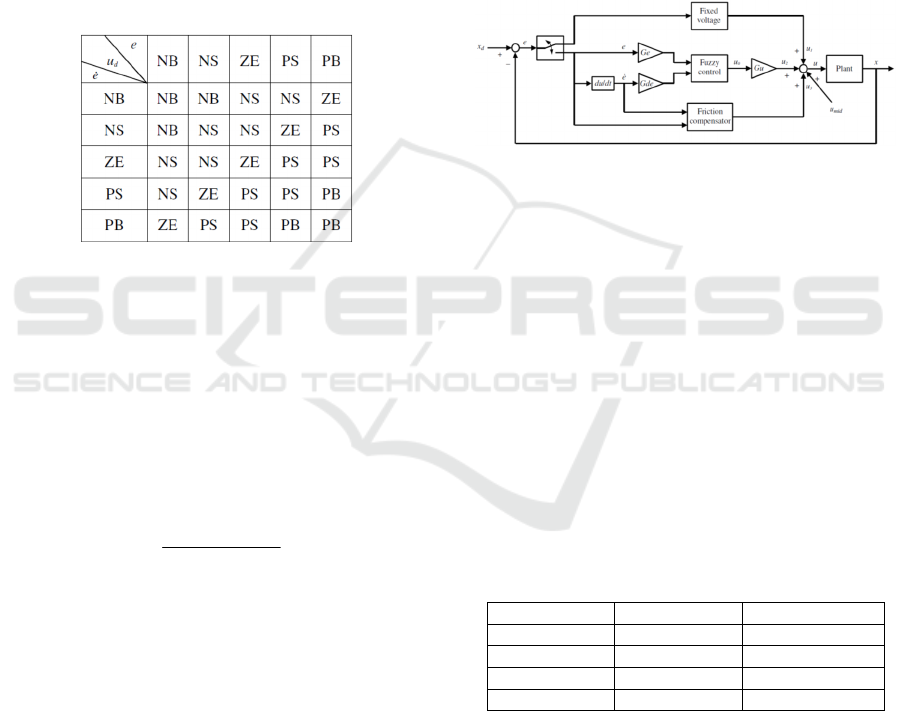
control system, respectively. Then, the fuzzy rule
table is established in Table 1.
Table 1: The rule table.
The output of the fuzzy controller is still a
linguistic variable. As a plant under control requires
a nonfuzzy value of control, the fuzzy control output
must be converted into a numerical value by a so-
called center of area method (COA). In this method,
the defuzzification is carried out by computing the
center of area of the consequence fuzzy sets
resulting from the inference mechanism. All
supports of fuzzy sets are considered in calculating
the output. The output equation is
n
i
i
n
i
ii
w
wO
u
1
1
0
)
~
max(
(2)
where
i
w
is the membership value and
i
O
~
is the
output of inference mechanism.
As shown in Figure 5, the proposed control
scheme is composed of a fixed voltage, a fuzzy
controller, and a friction compensator in this paper.
The controller output gives a bigger preset fixed
voltage into the system to reduce the rise time while
the control system has a bigger tracking error which
is bigger than a preset value (i.e.
1
|)(| cte
) or to
overcome the static friction in the beginning. When
the tracking error converges to be equal to or smaller
than the preset value (i.e.
1
|)(| cte
), the controller
output is switched from the fixed voltage part to the
fuzzy control with friction compensator. Firstly, the
fuzzy control is applied to produce the input value u
0
.
The fuzzy control method has been described
previously. While the tracking error reduces
gradually, the output of fuzzy control also follows
the tracking error to reduce gradually. The sliding
table will not move under the effect of friction and
then it results in a bigger tracking error. In order to
overcome this problem, there is a design strategy for
compensating the friction effect to achieve a more
precise positioning accuracy. Hence, the friction
compensator start to work when the tracking error is
bigger than a preset value (i.e.
2
|)(| cte
).
Figure 5: Block diagram of fuzzy control with friction
compensation.
4 EXPERIMENTAL RESULTS
In the experimental analysis and validation of the
position control performance for the proposed
control scheme on the pneumatic positioning system,
two step-typed reference command signals are set as:
Experiment 1: 5000μm for 0~6 second, 10000μm for
6~12 second, and 5000μm for 12~18 second.
Experiment 2: 8000μm for 0~6 second, 6000μm for
6~12 second, and 10000μm for 12~18 second.
The fixed voltages and control gains are set and
displayed in Table 2 for experiments 1 and 2.
Table 2: Fixed voltage and Control gains.
Control values Experiment 1 Experiment 2
Fixed voltage 0.15V, -0.1V 0.25V, -0.08V
Ge 1 1
Gde 1 1
Gu 2 1.2
Preset values c
1
and c
2
of tracking error for
switching control and starting friction compensator
are chosen to be equal to 0.5mm and 20nm,
respectively. For the friction compensator, the
schematic diagram of friction compensation design
is shown in Figure 6.
Fuzzy Control with Friction Compensation for a Pneumatic Positioning System
473
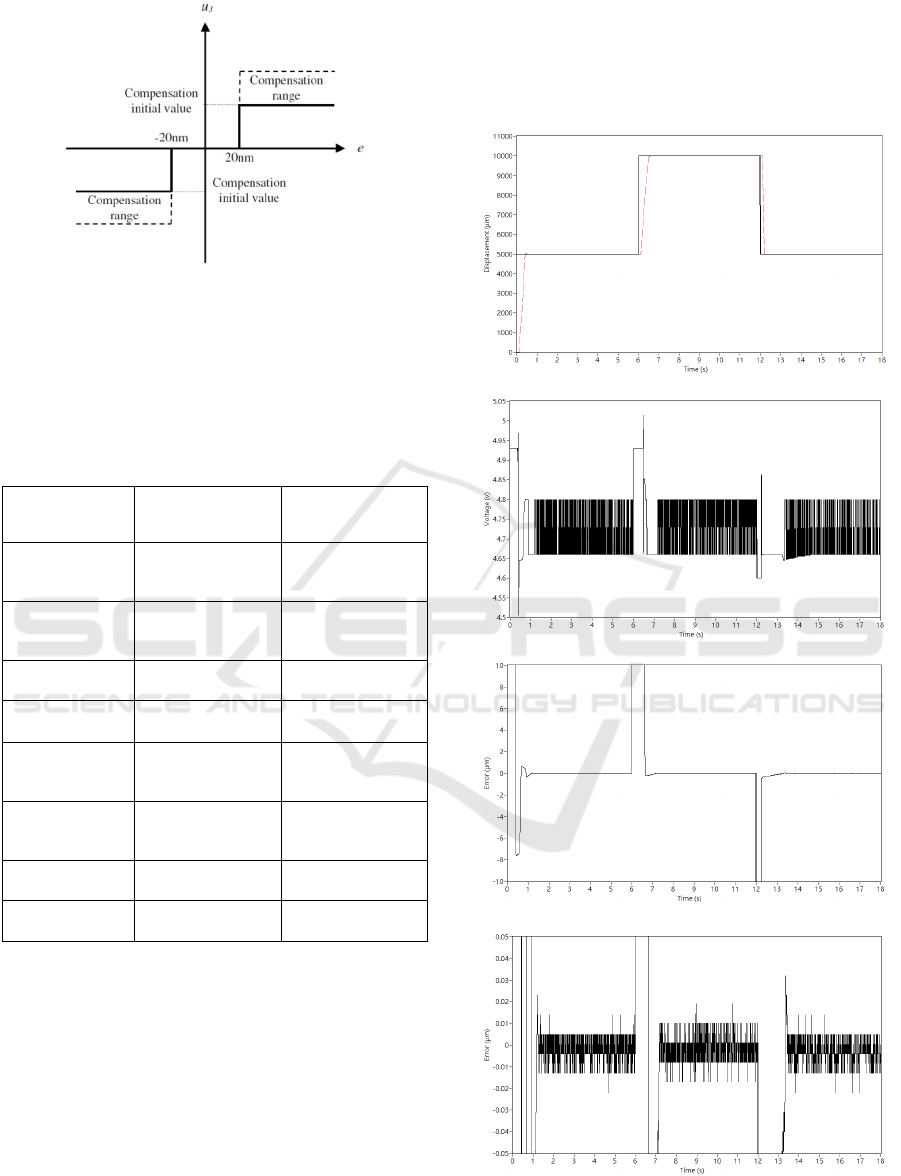
Figure 6: Schematic diagram of compensation design.
All the compensation values are set and
displayed in Table 3 for experiments 1 and 2. The
increasing value or the reducing value is the raising
quantity or reducing quantity for every 0.005 second
in experiments.
Table 3: Compensation Design Parameters.
Compensation
Parameters
Compensation
Values
(Experiment 1)
Compensation
Values
(Experiment 2)
Compensation
Range (
nm20e
)
0.07V~0.13V 0.08V~0.12V
Compensation
Initial Value (
nm20e
)
0.07V 0.08V
Increasing Value (
nm20e
)
0.005V 0.003V
Decreasing Value
(
nm20e
)
-0.005V -0.005V
Compensation
Range (
nm20e
)
-0.07V~-0.03V -0.035V~-0.02V
Compensation
Initial Value (
nm20e
)
-0.03V -0.02V
Increasing Value (
nm20e
)
0.005V 0.001V
Decreasing Value
(
nm20e
)
-0.002V -0.001V
Figures 7 and 8 show that the experimental
results of positioning control were performed in
Experiments 1 and 2, respectively. From the
displacement responses of sliding table shown in
Figure 7 (a) and Figure 8 (a), it is indicated that the
sliding table can reach the target position in 1 second.
Control input voltages of proportion valve are
displayed in Figure 7 (b) and Figure 8 (b). Figure 7
(d) and Figure 8 (d) shows that all the steady-state
errors are smaller than 30nm in Experiments 1 and 2.
It is indicated distinctly that the proposed control
scheme can achieve a high positioning accuracy. In
addition, since positioning stability is an important
performance index for control system, a total of 30
experimental trials for Experiment 1 and Experiment
2 were performed individually. It is noted that all the
steady-state error with smaller than 30nm are
confirmed in all experiment trials.
(a) Sliding table displacement and reference command.
(b) Control voltage
(c) Tracking error (
μm10
range)
(d) Tracking error (
nm50
range)
Figure 7: Time responses of fuzzy control with friction
compensation in experiment 1.
ICINCO 2016 - 13th International Conference on Informatics in Control, Automation and Robotics
474
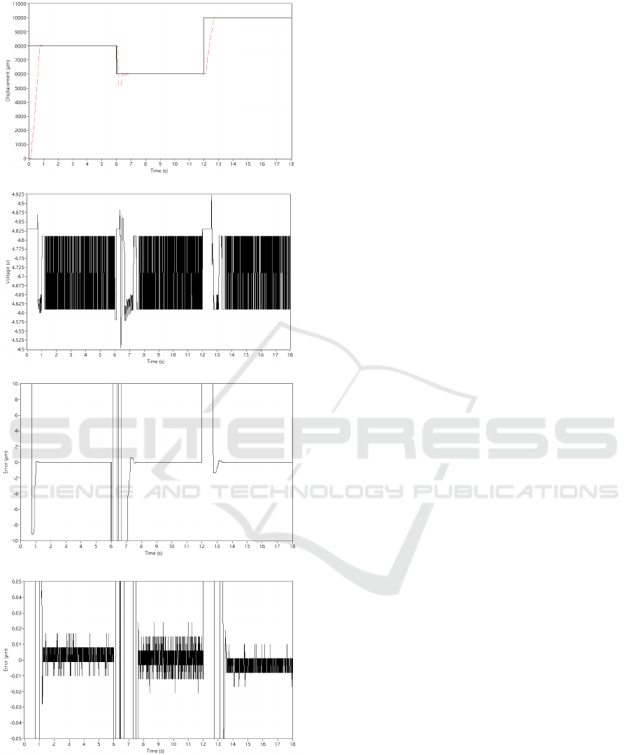
(a) Sliding table displacement and reference command.
(b) Control voltage
(c) Tracking error (
μm10
range)
(d) Tracking error (
nm50
range)
Figure 8: Time responses of fuzzy control with friction
compensation in experiment 2.
5 CONCLUSIONS
In this paper, a control scheme of fuzzy control with
friction compensation was proposed and applied to
the pneumatic positioning system. Through
experimental examinations, the proposed control
scheme that could significantly improve the
positioning performances in the pneumatic
positioning system was demonstrated and
confirmed. Main results are given as follows,
(1) The fuzzy control with friction compensation
could be successfully applied to the pneumatic
positioning system with the positioning accuracy
under nanometer order.
(2) According to 30 experimental positioning trials
for stepwise forward and backward actuation
commands, the positioning accuracy with less
than 30nm on the pneumatic positioning system
was verified in this paper.
REFERENCES
Paul, A.K, Mishra, J.E., Radke, M.G., 1994. Reduced
Order Sliding Mode Control for Pneumatic Actuator.
IEEE Transactions on Control Systems Technology,
Vol. 2, pp. 271-276.
Song, J., Ishida, Y., 1996. A robust sliding mode control
for pneumatic servo systems. International Journal of
Engineering Science, Vol. 35, pp. 711-723.
Korondi, P., Gyeviki, J., 2006. Robust Position Control for
a Pneumatic Cylinder. Proceedings of the 12th Power
Electronics and Motion Control Conference, pp. 513-
518.
Liu, Y.T.,
Kung, T.T., Chang, K.M.,
Chen, S.Y., 2013.
Observer-based adaptive sliding mode control for
pneumatic servo system. Precision Engineering, Vol.
37, pp. 522-530.
Gross, D.C., Rattan, K.S., 1998. An adaptive multilayer
neural network for trajectory tracking control of a
pneumatic cylinder. Proceedings of IEEE
International Conference on Systems. Man and
Cybernetics, Vol. 2, pp. 1662–1667.
Shih, M.C., Ma, M.A., 1998. Position control of a
pneumatic cylinder using fuzzy PWM control method.
Journal of Mechatronics, Vol. 8, pp. 241- 253.
Liu, Y.T., Lee, C.H., Fung, R.F., 2004. A Pneumatic
Positioning Device Coupled with Piezoelectric Self-
Moving Mechanism. Asian Journal of Control, Vol. 6,
pp.199-207.
Chiang, M.H., Chen, C.C., Tsou, T.N., 2005. Large stroke
and high precision pneumatic piezoelectric hybrid
positioning control using adaptive discrete variable
structure control. Mechatronics, Vol. 15, pp. 523-545.
Liu, Y.T., Jiang, C.C., 2007. Pneumatic Actuating Device
with Nanopositioning Ability Utilizing PZT Impact
Fuzzy Control with Friction Compensation for a Pneumatic Positioning System
475

Force Coupled with Differential Pressure. Precision
Engineering, Vol. 31, pp. 293–303.
Pai, K.R., Shin, M.C., 2003. Nanoaccuracy Position
Control of a Pneumatic Cylinder Driven Table.
International Journal of JSME. Series, Vol. 46, pp.
1062-1067.
Liu, Y.T., Chang, K.M., Lee, H.R., 2011. Study of a
precision pneumatic positioning device using PZT
dither. International Journal of Automation
Technology, Vol. 5, pp. 780-785.
ICINCO 2016 - 13th International Conference on Informatics in Control, Automation and Robotics
476
