
Adaptive Control of Mobile Manipulator Robot based on Virtual
Decomposition Approach
Abdelkrim Brahmi
1
, Maarouf Saad
1
, Guy Gauthier
1
, Wen-Hong Zhu
2
and Jawhar Ghommam
3
1
Electrical Engineering Department, École de Technologie Supérieure, Montréal, QC, Canada
2
Space Exploration Canadian Space Agency,
Montréal, QC, Canada
3
Ecole National d’Ingenieurs, Research Unit on Mechatronics and Automation Systems, Sfax, Tunisia
Keywords: Virtual Decomposition Control, Adaptive Control, Centralized/Decentralized Control, Mobile Manipulator
Robot.
Abstract: This paper presents an adaptive control scheme for a mobile manipulator robot based on the virtual
decomposition control (VDC). The control strategy was tested on three degrees of freedom manipulator arm
mounted on two degrees of freedom mobile platform to track a desired trajectory. The desired trajectory
is obtained from the workspace trajectory using the inverse kinematics. Differently to the known
decentralized control that divides the mobile manipulator into two subsystems, in this paper, the mobile
manipulator has N degrees of freedom, divided virtually into N subsystems. The applicability of the
proposed scheme is demonstrated in real time validation. The experimental results show the effectiveness of
the VDC approach.
1 INTRODUCTION
The need for robots capable of locomotion and
manipulation has led to the design of mobile
manipulator robot (MMR) platforms. A mobile
manipulator is a robotic manipulator arm mounted
on a mobile platform. Typical examples of MMR
include satellite arms, underwater robots in seabed
exploration and vehicles used in extra-planetary
exploration. The mobile manipulator comprises two
subsystems, that is, the mobile platform and the
manipulator arm subsystem.
However, this
significantly complicates the robotic system as its
control design complexity increases greatly. The
problem of controlling the mechanical system lies in
the fact that it imposes a set of kinematic constraints
on the coordination of the position and velocity of
the mobile manipulator. Few works have been
proposed to solve the control problem of these
robotic systems, which have high degrees of
freedom and are tightly interconnected.
In the recent years, the research in the design,
control, stability, and path tracking of mobile
manipulators have significantly increased. Most of
these studies have thus far focused on the tracking
control of mobile manipulators. Two main schemes
of control are developed in the literature: The first
one is centralized control, in which the mobile
manipulator is regarded as one system and the
controller is designed for the full system. The second
one is the decentralized control, in which controllers
for two subsystems are designed separately and no
coupling is considered. In the first approach, where
the mobile platform and the manipulator arm are
regarded as a complete system, many control
approaches were developed and implemented. In
(Yamamoto and Yun 1994), the authors focused on
the interaction between the manipulator arm and the
mobile platform. A nonlinear feedback control was
developed to compensate the dynamic interaction.
Studies discussing the problem of modeling and
control of mobile manipulator were given in (Chung
and Velinsky 1998, Seraji 1998, Song et al. 2005,
Aviles et al. 2012, Galicki 2012), where the robotics
system is considered as a complete system. Many
other works have used decentralized control for this
type of robotic systems as in (Tan and Xi 2001, Ngo
et al. 2007, Ge et al. 2008, Chen et al. 2015) where
the manipulator arm and the mobile platform are
viewed as two separated subsystems. LQR controller
for mobile manipulator was proposed (Chen et al.
2015), where the manipulator arm and the mobile
254
Brahmi, A., Saad, M., Gauthier, G., Zhu, W-H. and Ghommam, J.
Adaptive Control of Mobile Manipulator Robot based on Virtual Decomposition Approach.
DOI: 10.5220/0005975402540261
In Proceedings of the 13th International Conference on Informatics in Control, Automation and Robotics (ICINCO 2016) - Volume 2, pages 254-261
ISBN: 978-989-758-198-4
Copyright
c
2016 by SCITEPRESS – Science and Technology Publications, Lda. All rights reserved
platform are controlled independently. In (Ge et al.
2008) a sliding mode control was proposed to
control the mobile platform and a nonsingular
terminal sliding mode control for the manipulator's
arm.
Conventional control approaches consider
integrated mobile manipulator dynamics. However,
in practice, it becomes very difficult to get the exact
model and uncertainties may still exist. In (Wu and
Sun 2014) an adaptive tracking control scheme was
proposed for a mobile manipulator with the presence
of uncertainties and disturbance based on suitable
reduced dynamic model. An adaptive sliding mode
controller based on the backstepping applied to the
trajectory tracking of the wheeled mobile
manipulator was introduced in (Chen et al. 2013).
An adaptive control scheme based on suitable
reduced dynamic model was proposed in (Dong
2002), without considering any disturbance. To
overcome the problem of dynamic modeling and
dynamic control, some researchers proposed
adaptive control based on neural network control
and fuzzy logic approaches. For instance, non-
model-based techniques have been developed for a
different type of mobile manipulator robot with
dynamic parameters uncertainties (Mai and Wang
2014, Peng et al. 2014, Wu et al. 2014).
A. Main Contribution
All previous studies based on Lagrangian or
Newton/Euler approaches require knowledge of the
exact parameters of the system. In practice, this is
difficult, and the obtained model is usually
uncertain. For these types of systems with large
degrees of freedom, and which are tightly coupled,
adapting the parameters using methods based on full
dynamics is very complicated due to the huge
number of parameters involved.
To overcome, this problem we propose in this
paper a novel adaptive decentralized approach based
on an extension of the virtual decomposition control
(VDC) methodology in ( Zhu 2010, Brahmi et al.
2013) originally designed for fixed-base robotic
systems with large degrees of freedom. Some of the
many advantages of this approach are: 1) the whole
dynamics of the system can be easily found based on
the individual dynamics of each subsystem; 2) the
control only uses subsystem dynamics while
guaranteeing the stability of the entire system; and
3) it makes the adaptation of the physical parameters
very simple and systematic.
In opposite to known decentralized control
techniques that divide the mobile manipulator into
two subsystems, in our work, if the mobile
manipulator that has N degrees of freedom then the
robotics system is divided virtually into N
subsystems. This simplifies the control and the
dynamic parameters adaptation.
The rest of the paper is organized as follows.
Section 2 presents the modeling of the system while
section 3 presents the control problem statement.
Section 4 explains the control design and
experimental results are given in section 5. Finally, a
conclusion is given in section 6.
2 MODELING AND SYSTEM
DESCRIPTION
Before Before giving the rationale behind the virtual
decomposition approach, we start by giving a brief
formulation of the kinematic and dynamic modeling
of the mobile manipulator robot under consideration.
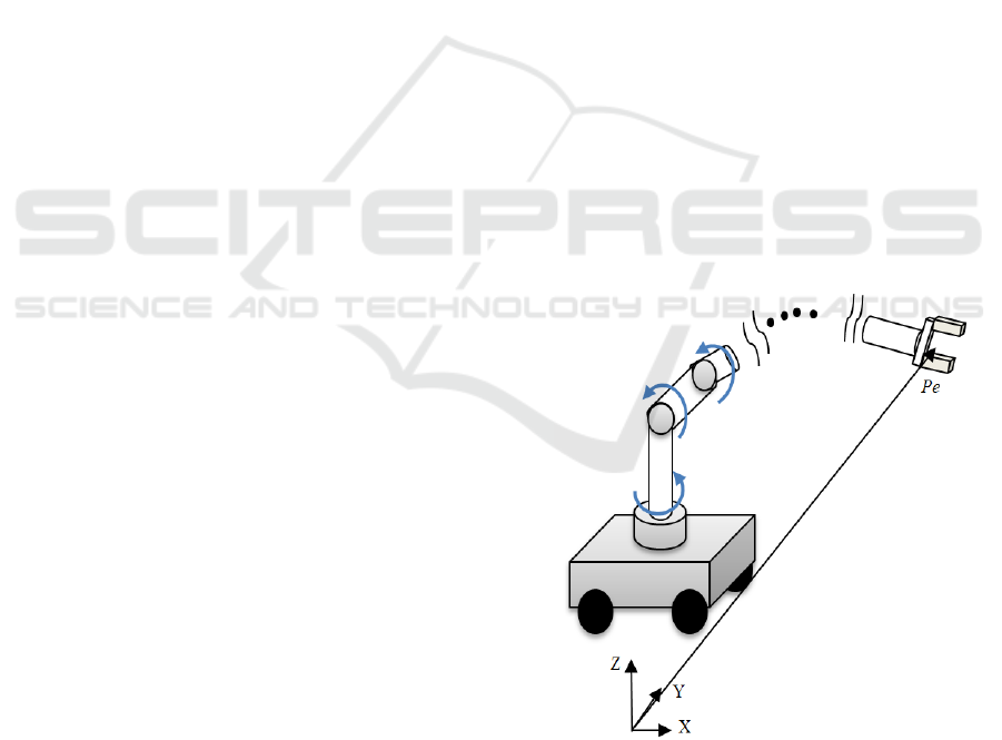
Figure 1 shows the holonomic manipulator arm
mounted on nonholonomic mobile platform, where
the manipulator has p-DOF, the mobile platform has
m-DOF and the full robotic system has n=m+p-
DOF.
Figure 1 shows the MMR with
e
P
being the
position/orientation vector of the MMR end–
effector.
Figure 1: n- DOF mobile manipulator robot.
2.1 Kinematics
The relationship between the end effector velocity
6
∈ \
e
V
of the mobile manipulator and the
Adaptive Control of Mobile Manipulator Robot based on Virtual Decomposition Approach
255

linear/angular velocity of mobile platform
,,
T
v
qxy
θ
⎡⎤
=
⎣⎦
and joints velocities of the
manipulator arm
[]
1
,..,
T
am
qqq=
is given by:
=
ee
VJq
(1)
where,
[, ]
Tn
va
qqq=∈
\
and
6×
∈ \
n
e
J
is the
Jacobian matrix.
2.2 The Mobile Manipulator Dynamics
The dynamic model of the mobile manipulator
developed using Lagrangian approach is given in the
general joint space by the following equation:
() ( ) ()
,
T
M
qq Cqqq Gq A
τλ
++=Ε+
(2)
where
×
∈ \
nn
M
is the mass matrix,
×
∈ \
nn
C
represents the Coriolis and centrifugal terms,
∈ \
n
G
is the vector of gravity,
,, ∈
\
n
qqq
are the
generalized coordinate vector, the joint velocity and
the acceleration vectors respectively ,
nk
E
×
∈ \
is a
full rank transformation matrix and
k
τ
∈ \
is the
input control vector,
×
∈\
rn
A
is the constraint
matrix and
r
λ
∈ \
is the constraint force.
The mobile manipulator robot is considered as a
fully actuated arm mounted on the nonholonomic
mobile platform. This nonholonomic constraint is
given as:
() 0Aqq=
(3)
The objective is to eliminate the term of
constraint
T
A
λ
, using the kinematic equations of the
mobile platform and the right and the left wheels’
angular velocities
R
q
and
L
q
that are obtained by the
following expression:
()qSq
η
=
(4)
where,
[, ]
T
va
qqq=
is the generalized coordinate
linear/angular velocities,
()Sq
is in the null space of
the kinematic constraint matrix
()
A
q
and
[,,]
T
RLa
qqq
η
=
are the generalized coordinate
angular right/left wheels velocities and the
manipulator joint velocities. Therefore, we obtain:
() () 0
TT
SqAq=
(5)
Based on (2), (4) and (5) the dynamic model (2)
can be expressed by a linear relationship of the form:
() ( ) () ( )
,,,,qqqqWqq
η
ηηητ
Η+Β +ℑ= Γ=
(6)
where
()
T
qSMSΗ=
,
()
()
T
B
qSMSCS=+
,
()
T
qSGℑ=
The physical parameters of the robot
are unknown and had to be estimated. Using the
estimate parameters of
Γ
, noted
ˆ
,Γ
the equation of
parametrization expression can be written as:
() ( ) () ( )
ˆ
ˆˆ ˆ
,,,,qqqqWqq
ηη ηη
Η+Β +ℑ= Γ
(7)
In the classical decentralized/centralized
approach based adaptive control, it’s very difficult to
obtain these parameters when the degree of freedom
increases. Usually, the size of the parameters vector
Γ can be greater than 100 in this category of robots (
Zhu 2010, Brahmi et al. 2013). As a solution of this
serious problem, we use a novel adaptive control
based on the virtual decomposition approach where
the problem of control and adaptation of parameters
are converted to each rigid body and each joint.
To simplify the control formulation, the
following assumption is made:
Assumption 2.1: All the joints’ velocities of the
mobile manipulator robots are available for
feedback.
The dynamics given in equation (6) has the
following properties:
Property 2.1: the matrix H is symmetric positive
definite.
Property 2.2: the matrix
2QH B=−
is skew
symmetric, that is, for any vector x, we have:
()
20
T
xH Bx−=
3 CONTROL PROBLEM
STATEMENT
The idea of the VDC is to break down the robotic
system into a graph consisting of several objects and
open chains. An object is a rigid body and open
chain consists of a series of rigid links connected
one by one by a hinge and has a certain degree of
freedom. The dynamic coupling between the
subsystems can be represented by the flow of virtual
power (FVP) at the cutting point. This refers to the
principle of virtual work (Zhu 2010, Brahmi et al.
2013) and results in one open chain.
For the controller design, only the dynamics of
the rigid bodies and the joints are required.
The control objective is to generate a set of
torque inputs such that the joint position’s tracking
error converges asymptotically to zero. Formally
speaking, the control problem is to design the
control input:
ICINCO 2016 - 13th International Conference on Informatics in Control, Automation and Robotics
256
()
,
f
qq
τ
=
such that the following limits hold:
lim 0, lim 0
dd
tt
qq qq
→∞ →∞
−= −=
where,
n
q ∈ \
,
∈ \
n
d
q
are the measured and
desired joint angular position and velocity of the
mobile manipulator.
4 CONTROL DESIGN
The overall control system is designed using the
following steps:
- The joint space desired trajectories are obtained
from the workspace desired trajectories using the
inverse kinematics(1).
- The required joint space trajectory are computed
from the desired trajectory in joint space.
- The required velocity
6
∈ \
rn
B
V
of the n body-
fixed frames
j
B illustrated in Figure 2. is calculated.
- The VDC approach is used to simplify the
problem of adaptation of the parameters of the
complete system, where this problem is converted
into a problem of estimation of the parameters of
each subsystem. From the velocities computed in the
first step, the estimated parameters are calculated.
- The control law of the mobile manipulator robot is
finally designed.
4.1 Design
Step 1: the desired joint velocity
∈
\
n
d
q
is
calculated based on (1), and then the required joint
velocities are by
r
q
()
r
dpd
qqKqq=+ −
(8)
with
p
K
is a positive gain matrix.
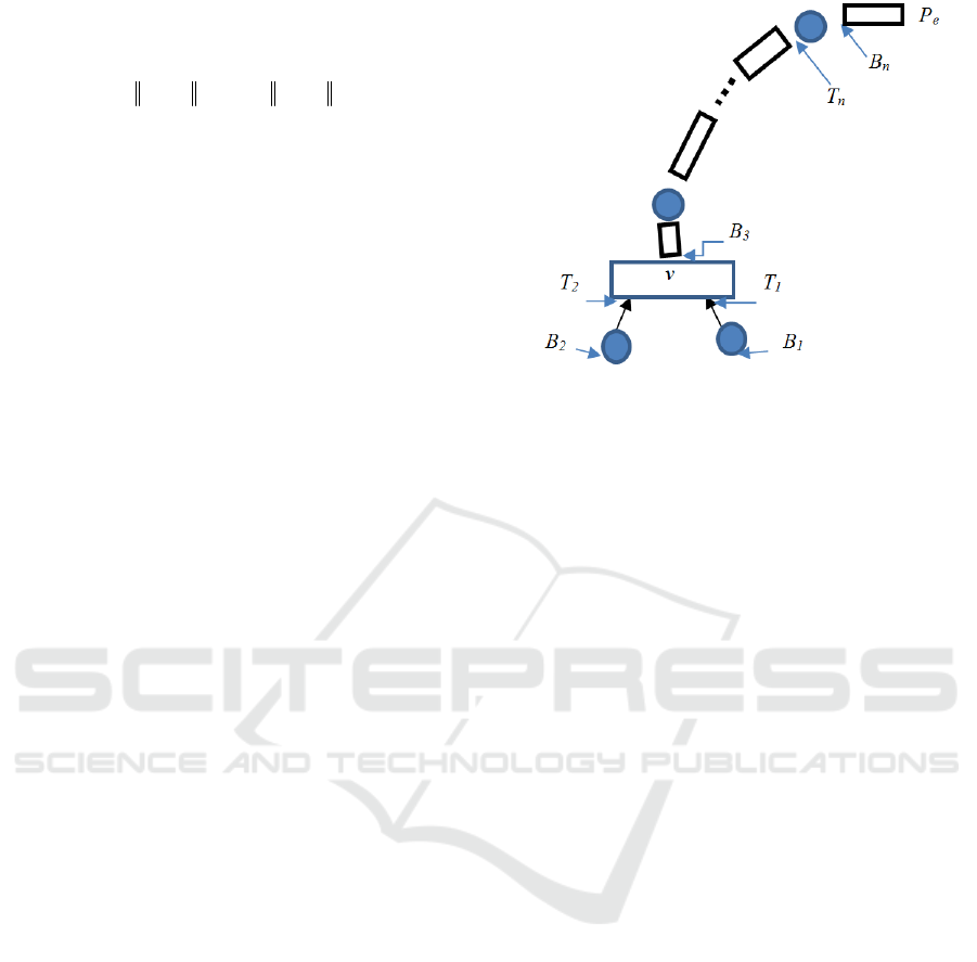
Step 2: In this step, the goal is to virtually
decompose ( Zhu 2010, Brahmi et al. 2013) the
robotic system into several parts and open chain
elements. Each part is a rigid body and open chain
consists of a series of rigid links connected one by
one. This decomposition is illustrated in Figure 2.
Figure 2: Virtual decomposition of the MMR.
In this step the linear/angular velocity vectors of
each frame B
j
is defined as:
1
1
,..., , , ,...,
n
T
TT
BnvBB
VqqVVV
⎡
⎤
=
⎣
⎦
and is calculated as
follows:
11
1
j
j
Jj
B
T
BjBB
Vzq UV
++
+
=+
(9)
where,
j
q
is the joint velocity,
6
j
B
V ∈ \
the linear
and angular velocity of the corresponding frame,
6
v
V ∈ \
is the velocity of the mobile platform and z
is defined as
[]
0 0 1000=
T
z
for prismatic axes and
as
[]
0 0 0001=
T
z
for revolute axes.
The transformation matrix of force/moment
vectors from frame B to frame A is defined by:
()
33
0
×
⎡
⎤
⎢
⎥
=
⎢
⎥
⎣
⎦
A
B
A
B
AA A
A
BB B
R
U
Sr R R
(10)
where
33×
∈ \
A
B
R
is the rotation matrix between
frames A and B, and
()
33×
∈ \
A
AB
Sr
is a skew
symmetric matrix built from the vector
33×
∈ \
A
AB
r
linking the origins of frames A and B, expressed in
the coordinates of frame A.
The velocity vector is defined as follows:
1
1
,..., , , ,...,
n
T
rrr rT rT
BnvBB
VqqVV V
⎡
⎤
=
⎣
⎦
where
r
j
q
are the joint velocities, and the
6
∈
j
r
B
VR
vectors represent the velocity of each frame Bj.
The following relates the velocity propagation
along the structure:
Adaptive Control of Mobile Manipulator Robot based on Virtual Decomposition Approach
257

11
1
++
+
=+
j
j
Jj
B
rr Tr
BjBB
Vzq UV
(11)
In general, we can write the system in a matrix
form by using the Jacobian matrix:
=
rr
Bn
VJq
(12)
with
1
1
,..., , , ,...,
n
T
rrrTrT
BnvBB
VqqVV V
⎡⎤
=
⎣⎦
and
7 ×
∈ \
nn
n
J
being the VDC Jacobian matrix of the system.
The dynamics of the j-th rigid body is given in
the linear form by the following equation:
*
*
jjjjj
BBBBBBj
vvvvvv
F
MV CV G
F MVCVG
⎧
=++
⎪
⎨
⎪
=++
⎩
(13)
with
66
,
j
Bv
MM
×
∈ \
being the matrix of inertial
term,
66
,
j
Bv
CC
×
∈ \
the matrix of
centrifugal/Coriolis term,
6
,
j
Bv
GG∈ \
the vector
related to the gravity. The vector of resulting forces /
moments acting on the rigid body is computed by an
iterative process as follows:
1
11
11 2 2 3 3
2
22 22
1
11 11
*
**
*
*
*
nn
n
nn nn
BB
B
BB BB
vv v
vv TT TT BB
B
BB TT
B
BB TT
FF
FF UF
F
FUFUFUF
FF UF
FF UF
−
−−
=
=+
== + −
=+
=+
#
(14)
The dynamic model of the j-th rigid link (13)
based on its required velocity is given by:
*
*
j
jj jj j jj
rrr
BBBBBBBB
rrr
vvvvvvvv
F MVCVGY
F MVCVGY
θ
θ
⎧
=++=
⎪
⎨
⎪
=++=
⎩
(15)
where,
13
,
j
Bv
θθ
∈
\
is the parameters’ vector of the
j-th rigid link, and
613
,
j
Bv
YY
×
∈ \
the dynamic regre
s sor matrix.
Since the physical parameters of the j-th rigid
body and the mobile platform are unknown and need
to be estimated, then the estimated vectors
ˆˆ
,
j
Bv
θθ
are used and the required force/moment is obtained
as follows:
()
()
*
*
ˆ
ˆ
j
jj j j j
rr
BBB BBB
rr
vvvvvv
FY KVV
FY KVV
θ
θ
⎧
=+ −
⎪
⎨
⎪
=+ −
⎩
(16)
where,
ˆˆ
,
jjj
TT
Bj B B B v v v v
Ys Ys
θρ θρ
==
are the
adaptation functions, and are chosen to ensure
system stability,
()
()
,
jjj
rr
BBBvvv
s
VVsVV=− =−
,
and
,
j
Bv
ρρ
,
,
Bj v
KK
are positive gains.
The vector of the required resulting
forces/moments acting on the
j-th rigid body is given
by an iterative process ( Zhu 2010, Brahmi et al.
2013) as in (14).
The dynamics of the
j-th joint actuator is
expressed by the following equation:
()
*
,
τξ
=+
j
aj m j j j
J
qqq
(17)
where,
()
,
j
j
qq
ξ
represents the friction and
gravitation force / torque terms and
j
m
J
is the
moment of inertia of the motor driving this joint.
The dynamics (17) based on its required velocity is
expressed in the linear form by the following:
()
*
,
j
rrrr
aj m j j j aj aj
Jq qq Y
τ
ξ
θ
=+ =
(18)
where,
4
aj
θ
∈ \
is the parameters’ vector of the j-th
joint actuator, and
14
aj
Y
×
∈ \
is the dynamic
regressor (row) vector, defined in ( Zhu 2010,
Brahmi et al. 2013). Since the physical parameters
of the
j-th actuator are unknown and need to be
estimated, then the estimated vector
ˆ
θ
aj
is used and
the dynamic (18) becomes:
()
*
ˆ
rr
aj aj aj aj j j
YKqq
τθ
=+ −
(19)
where,
ˆ
jjj
T
aj a a a
Ys
θρ
=
is the adaptation function, and
is chosen to ensure system stability,
()
=−
j
arjj
s
qq
,
and
ρ
j
a
,
aj
K
are positive gains.
Finally, the input control torque at the
j-th mobile
manipulator’s joint is computed from the desired
torque obtained from (19)
*r
aj
τ
and the required force
at cutting point
B
j
, identified
j
r
B
F
as:
*
j
rTr
aj B
zF
ττ
=+
(20)
Lemma 4.1: Consider the j-th rigid dynamics (13,
14) and the joint actuator dynamics (17), under the
control design (16, 19 and 20) and the boundedness
of the estimated parameters. The control objective is
satisfied and the error tracking states are
asymptotically stable.
ICINCO 2016 - 13th International Conference on Informatics in Control, Automation and Robotics
258
Proof: Consider the Lyapunov function candidate:
11
nn
j
aj p
jj
VV VV
==
=+ +
∑∑
(21)
where
j
V is a non-negative Lyapunov candidate
function related to the
j-th rigid link,
aj
V is a non-
negative Lyapunov candidate function of the
j-th
joint and
p
V is a non-negative Lyapunov candidate
function of the mobile platform. These three
Lyapunov candidate functions are chosen as follow:
()()
(
)
()
()
()()
()
2
2
2
1
2
1
13
1
2
1
4
2
11
22
11
13
11
22
1
jj jjj
BB
ji ji
B
ji
aj aj
ii
j
a
i
vv
ii
v
i
n
T
rr
jBBBBB
j
i
n
r
aj m j j
ji
T
rr
pvvvvv
i
VVVMVV
VJqq
VVVMVV
θθ
ρ
θθ
ρ
θθ
ρ
=
−
=
−
==
−
=
⎧
⎡⎤
=− −
⎪
⎢⎥
⎣⎦
⎪
⎪
⎪
+
⎪
⎪
⎨
⎡⎤
⎪
=−+
⎢⎥
⎪
⎢⎥
⎪
⎣⎦
⎪
⎪
=− −+
⎪
⎩
∑
∑
∑∑
∑
(22)
where
,,,,and
ji ji i i i i
B B v v aj aj
θ θ θθθ θ
are the i-th
elements of the corresponding vector parameters.
The first derivative of the Lyapunov candidate
function (21) is given as follows:
11
nn
j
aj p
jj
VV VV
==
=+ +
∑∑
(23)
By using the definition of the virtual power and
the choice of the parameter function adaptation as in
(16) and (19); it is straightforward to prove that
V
is
always decreasing and is given as follows:
()()
()()()
1
2
1
jj jjj
j
n
T
rr
BB BBB
j
n
T
rr r
ajj vv vvv
j
VVVKVV
K
qq VV KVV
=
=
=− − −
−−−− −
∑
∑
(24)
The stability analysis shows that
V
is always
decreasing and the system is asymptotically stable in
the sense of Lyapunov. The reader can found the
detailed proof stability in ( Zhu 2010).
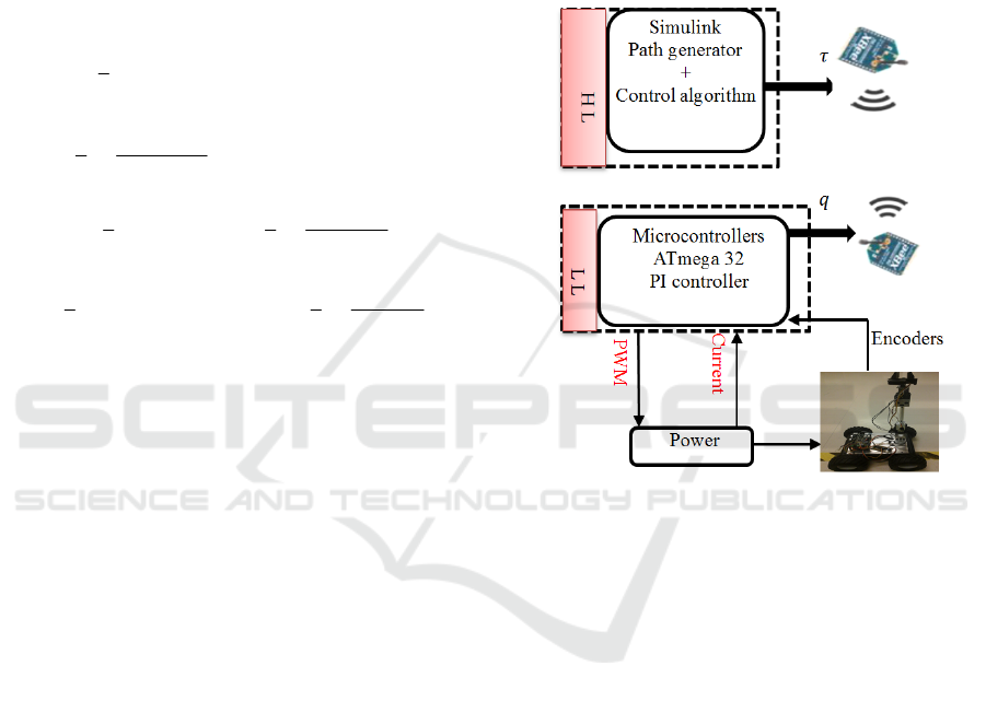
5 EXPERIMENTAL RESULTS
Experimental implementation is carried out on a 3-
DOF MMR as illustrated in Figure 3. A Zigbee
technology communication is used between the
application program implemented in Simulink
Matlab® and the mobile manipulator robot.
The VDC
approach is implemented in real time using Real-Time
Workshop (RTW) of Mathworks
®
.
Figure 3 shows the
complete structure design of the control. This block
diagram consists of Zigbee communication, low level
(LL) controller (PI controller) and High level (HL)
controller (virtual decomposition control) and
measurement sensors (encoders).
Figure 3: Real-time setup.
The control strategy was tested on 3-DOF mobile
manipulator robot to track a desired trajectory in
Cartesian space presented in Figure 4. The two
wheels of the
j-th mobile manipulator robot platform
are actuated by two DC-motors HN-GH12-2217Y
(DC-12V-200RPM 30:1) and its angular positions
are given by using encoder sensors (E4P-100-079-
D-H-T-B). All joints of the arm manipulator are
actuated by Dynamixel motors (MX-64), this
actuated gives the measurement of different
parameter’s as the angular position, the angular
velocity, the torque and many others parameters
used in the control and analysis. In this experimental
test the Dynamixel motors are configured to be
controlled on torque mode and are linked to ATmega
32 via TTL level multi drop bus.
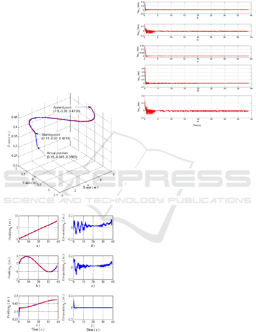
The starting point is
()
0.14, 0.02, 0.4214
ei
P =−
,
the final point is
()
7.8, 0.28,0.4759
ef
P =−
, without
end-effector orientation along X, Y or Z-axis and the
actual end-effector mobile manipulator robot
position is
()
0.18, 0.045, 0.3565
ef
P =−
. The inverse
Adaptive Control of Mobile Manipulator Robot based on Virtual Decomposition Approach
259
kinematics is used to transform the trajectory
generated in the workspace to the joints space. The
controller gains are chosen as follows:
()
21.2,8,130,3.7,3.7 , 0.8, 0.7, 0.8
j
pvBaj
KKKK====.
The sampling time is set to 0.015 seconds.
The trajectory tracking in the Cartesian space is
presented in Figure 4 and Figure 5 (a-b-c). It can be
seen a good position tracking from Figure 5 (a-b-c).
This good tracking is confirmed by the related errors
between the desired values and the real ones shown in
Figure 5 (d-e-f). All the input torques of the three
joints of the arm manipulator and that of the right/left
wheels are illustrated in Figure 6 (a-b-c-d-e).
Figure 4: Desired trajectory of manipulator’s end effector.
Figure 5: (a) Tracking trajectory of x-position, (b)
Tracking trajectory of y-position (c) Tracking trajectory of
z-position, (d) Tracking error of x-position, (e) Tracking
error of y-position (f) Tracking error of z- position.
Figure 6: (a) The input torque of the joint 1, (b) The input
torque of the joint 2 (c) The input torque of the joint 3, (d)
The input torque of the right wheel 1, (e) The input torque
of the left wheel.
6 CONCLUSIONS
In this paper, a decentralized control based on the
virtual decomposition strategy was presented to
control three degrees of freedom mobile manipulator
robot to track desired trajectories generated in
Cartesian space. The control law is designed based
on the virtual decomposition approach, and the
global stability of the systems is proven through the
virtual stability of each subsystem. The proposed
control design ensures that the workspace position
error converges to zero asymptotically. The
experimental results showed the effectiveness of this
control approach where the tracking errors of the
desired trajectory in workspace converge to zero.
REFERENCES
Aviles, L. A. Z., J. C. P. Ortega and E. G. Hurtado (2012).
"Experimental Study of the Methodology for the
Modelling and Simulation of Mobile Manipulators.",
International Journal of Advanced Robotic Systems,
Vol 9, 192.
Brahmi, A., M. Saad, G. Gauthier, W.-H. Zhu and J.
Ghommam (2013). Real time control of ANAT robot
manipulator using virtual decomposition approach.
IEEE, 3rd International Conference on Systems and
Control (ICSC).
ICINCO 2016 - 13th International Conference on Informatics in Control, Automation and Robotics
260

Chen, H., Y. Zhao and J.-m. Lee (2015). " LQR control
for a Mobile Manipulator using COG feedback. "
IEEE, International Conference on Advanced
Intelligent Mechatronics (AIM) .
Chen, N., F. Song, G. Li, X. Sun and C. Ai (2013). "An
adaptive sliding mode backstepping control for the
mobile manipulator with nonholonomic constraints."
Communications in Nonlinear Science and Numerical
Simulation 18(10): 2885-2899.
Chung, J. H. and S. A. Velinsky (1998). "Modeling and
control of a mobile manipulator." Robotica 16(06):
607-613.
Dong, W. (2002). "On trajectory and force tracking
control of constrained mobile manipulators with
parameter uncertainty." Automatica 38(9): 1475-1484.
Galicki, M. (2012). "Control of mobile manipulators in a
task space." Automatic Control, IEEE Transactions on
57(11): 2962-2967.
Ge, W., D. Ye, W. Jiang and X. Sun (2008). Sliding mode
control for trajectory tracking on mobile manipulators.
IEEE Asia Pacific Conference on Circuits and
Systems, APCCAS .
Mai, T.-L. and Y. Wang (2014). "Adaptive-backstepping
force/motion control for mobile-manipulator robot
based on fuzzy CMAC neural networks." Control
Theory and Technology 12(4): 368-382.
Ngo, M., N. Phuong, V. Duy, H. Kim and S. Kim (2007).
"Control of two wheeled welding mobile
manipulator." International Journal of Advanced
Robotics System 4(3): 293-302.
Peng, J., J. Yu and J. Wang (2014). "Robust adaptive
tracking control for nonholonomic mobile manipulator
with uncertainties." ISA transactions 53(4): 1035-
1043.
Seraji, H. (1998). "A unified approach to motion control
of mobile manipulators." The International Journal of
Robotics Research 17(2): 107-118.
Song, Z., D. Zhao, J. Yi and X. Li (2005). Tracking
control of mobile manipulator with dynamical
uncertainties. IEEE/RSJ, International Conference on,
Intelligent Robots and Systems (IROS 2005).
Tan, J. and N. Xi (2001). Integrated sensing and control of
mobile manipulators. In Proceedings of IEEE/RSJ,
International Conference on, Intelligent Robots and
Systems.
Wu, K. and W. Sun (2014). Adaptive tracking control for
a new mobile manipulator model. IEEE, International
Conference on Control (UKACC).
Wu, X., Y. Wang and X. Dang (2014). "Robust adaptive
sliding-mode control of condenser-cleaning mobile
manipulator using fuzzy wavelet neural network."
Fuzzy Sets and Systems 235: 62-82.
Yamamoto, Y. and X. Yun (1994). Modeling and
compensation of the dynamic interaction of a mobile
manipulator. Proceedings of IEEE, International
Conference on, Robotics and Automation.
Zhu, W.-H. (2010). Virtual Decomposition Control:
Toward Hyper Degrees of Freedom Robots, Springer
Science & Business Media.
Adaptive Control of Mobile Manipulator Robot based on Virtual Decomposition Approach
261
