
Architecture Viewpoint for Modeling Business Collaboration
Concerns using Workflow Patterns
Ayalew Kassahun and Bedir Tekinerdogan
Information Technology Group, Wageningen University, Hollandseweg 1, Wageningen, The Netherlands
Keywords: Architecture Viewpoint, Business Collaboration, Collaboration Viewpoint, Business Process Modeling,
Workflow Patterns.
Abstract: Businesses today rarely operate in isolation but must collaborate with others in a coordinated fashion. To
address collaboration concerns, business analysts need to design business processes. Business process
designs have a direct impact on the required software systems and the corresponding architectural design.
Conversely, the architectural design imposes constraints on the business process designs. Unfortunately,
business processes and software architectures are often designed separately leading to a misalignment
between the two. To bridge this gap we propose the architecture collaboration viewpoint to be used by
teams of business analysts and software architects when addressing business collaboration concerns. The
collaboration viewpoint uses elements from business process and architecture viewpoints to provide new
modeling artifacts for alignment. The design artefacts are mapping tables and workflow pattern diagrams
that are used to identify misalignments and redesign the business processes. The viewpoint facilitates the
communication between business analysts and architects. We illustrate the collaboration viewpoint for a
food supply chain transparency system from a real industrial case study.
1 INTRODUCTION
Businesses today rarely operate in isolation but must
collaborate with others in a coordinated fashion. To
address collaboration concerns business analysts
design business process models (BPMs) that
integrate business activities across the collaborating
organizations. BPMs have to be supported by
underlying software systems, and therefore, they will
have a direct impact on the required software systems
and the corresponding architectural design.
Conversely, the architectural design imposes
constraints on BPMs, and as a consequence, an
inherent, mutual dependency exists between these
two sets of designs.
Business collaboration involves BPMs that span
multiple organizations – which we hereafter refer to
as collaboration business processes. When realizing
collaboration business processes multiple software
systems need to be taken into account. As a result,
the mutual alignment of BPMs and architectural
designs becomes very cumbersome. We define the
difficulties associated in aligning the two designs as
business collaboration concerns.
The current practice addresses business process
concerns and architectural concerns separately, and
sequentially – first the BPMs are designed, then the
software architecture is designed using the BPM
models as inputs. This approach is to an extent
feasible if applied within the context of an individual
organization. However, when dealing with multiple
software systems the approach is not feasible due to
the mutual dependency between business process
models and the software architecture.
To address the problem we studied the existing
modelling approaches. At present, two distinct sets of
viewpoints are used to address business collaboration
concerns. Various architecture viewpoints are used
for modelling the structure of software systems and
are hereafter referred to as structural viewpoints.
Business process concepts and notations are used for
modelling business processes and are hereafter
referred to as the business process viewpoint. The
structural viewpoints do not directly address business
process concerns. Likewise, the business process
viewpoint does not consider architectural concerns.
As a consequence, a business-IT alignment problem
arises. The alignment problem has been discussed in
the context of individual organizations (Avison et al.
2004; Hong-Mei 2008; Bartens et al. 2014; Aversano
et al. 2016) but not in the context of business
collaborations.
In this paper we introduce the collaboration
viewpoint for addressing business collaboration
concerns and an iterative design approach for
Kassahun, A. and Tekinerdogan, B.
Architecture Viewpoint for Modeling Business Collaboration Concerns using Workflow Patterns.
DOI: 10.5220/0005973600270038
In Proceedings of the 11th International Joint Conference on Software Technologies (ICSOFT 2016) - Volume 1: ICSOFT-EA, pages 27-38
ISBN: 978-989-758-194-6
Copyright
c
2016 by SCITEPRESS – Science and Technology Publications, Lda. All rights reserved
27

applying it. In the collaboration viewpoint we use
architectural and business process viewpoints to
provide new kinds of models with the corresponding
method for applying them. We introduce mapping
tables and workflow pattern diagrams as a means of
identifying misalignment and redesigning the BPMs.
The collaboration viewpoint is meant as means of
enabling teamwork between software architects and
business process analysts. The teamwork ensures that
the business process and architecture views are well-
aligned and feasible. We illustrate the viewpoint in
real industrial case study for which a safety and
quality transparency system for food supply chains is
designed.
The remainder of this paper is organized as
follows. Section 2 provides background information.
Section 3 presents the case study used to demonstrate
the collaboration viewpoint. Section 4 presents the
collaboration viewpoint and a method for applying it.
In section 5 the viewpoint is applied to the case
study. In section 6 the related work is presented and
in section 7 concluding remarks are made.
2 BACKGROUND
In this section we first discuss the background on
software architecture, BPM, and workflow patterns.
2.1 Software Architecture
Software architecture defines the gross-level
structure of a software system (ISO/IEC/IEEE
2011). Architecture modeling is important to enhance
the understanding of the software system, support the
communication among stakeholders, and guide the
development process (Tekinerdogan 2014). A
common practice to modeling architecture is using
different architectural views that address the
concerns of a specific group of stakeholders.
Architectural views document the architectural
design decisions from a specific viewpoint. That
means, the designs documented in an architectural
view follow the conventions, including models and
notations, defined in the corresponding architectural
viewpoint. From a given architectural viewpoint one
or more architectural views can be designed
(Clements et al. 2010; ISO/IEC/IEEE 2011).
In the literature, a number of viewpoints have
been identified (Kruchten 1995; Hofmeister et al.
2000; Kruchten 2004; Lattanze 2008; Clements et al.
2010). The Views and Beyond (V&B) approach
identifies three major viewpoints: module,
component-and-connector (C&C), and allocation.
Module views deal with concerns related to
implementation, such as, decomposition and
generalization. The C&C and allocation viewpoints
are structural viewpoints since they largely refer to
the structure of the software system. The C&C views
deal with the interaction structure, such as, data flow
and message routing. The allocation viewpoint
describes how software elements are allocated to the
environment of the software system, such as,
hardware or development team (Clements et al.
2010).
Recognizing that new viewpoints may be needed
to address new kinds of concerns, the ISO/IEC 42010
standard for documenting software architecture
(ISO/IEC/IEEE 2011) provides an extensible
metamodel for defining new viewpoints.
2.2 BPM
A business process describes how the activities for
achieving a particular business outcome are
interrelated and how they are executed (Davenport
and Short 1998). The process modelling approach
has historically gained the attention of businesses
when it was effectively used to address inefficiencies
in functional organizations (Dumas et al. 2013). At
its core, a BPM identifies the events of the business
process and the series of activities that are triggered
by them (Dumas et al. 2013). In practice, business
processes are modeled by business analysts using
visual modelling methods. The most prominent
business processes modeling language is BPMN
(Business Process Model and Notation) (OMG
2011). BPMs address business requirements, and as
such, are inputs for the software architects as
requirements that should to be addressed in the
architectural design (The Open Group 2013).
2.3 Workflow Patterns
Workflow patterns are recurring problem-solution
pairs that have been frequently used in business
process modeling (Russell et al. 2006). In fact, BPMs
can be viewed as being composed of workflow
patterns. Since workflow patterns represent well-
known problem-solution pairs, it is easier to describe,
discuss and redesign a BPM by manipulating its
constituent workflow patterns.
In the past, more than a hundred workflow
patterns have been identified, categorized and
cataloged (van der Aalst and ter Hofstede 2011). The
most prominent categories are control-flow, data-
flow and resource-flow workflow patterns (Van der
Aalst et al. 2003). Control-flow patterns model the
execution ordering of activities and are the basis for
the patterns in the other categories. The data-flow
ICSOFT-EA 2016 - 11th International Conference on Software Engineering and Applications
28
patterns model how data flows along the flow of
control. The resource-flow patterns model how work
is assigned to resources (e.g. devices, people)
following the flow of control. Appendix A provides
the summary of workflow pattern categories and the
workflow patterns in each category.
3 ILLUSTRATIVE CASE AND
PROBLEM STATEMENT
In this section we use a case study from the FIspace
business collaboration research project (Verdouw et
al. 2014) to illustrate collaboration concerns and
describe the problem statement.
3.1 Case: Transparency in Food Supply
Chains
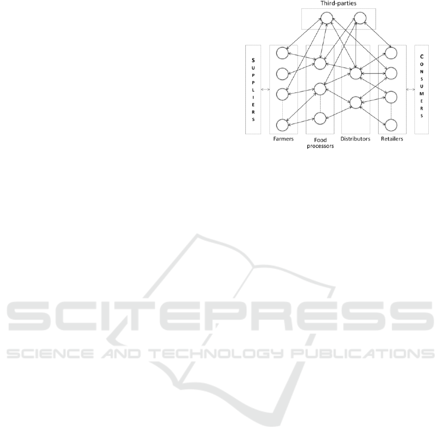
A food supply chain network is a collaboration
linkage of a series of food operators that transform
agricultural input products into finished food
products. The food operators involved include
farmers, a series of food processors and distributors,
and retailers. In addition, mandated by food
regulations, various third-parties are involved to
guarantee the safety and quality of food. In Europe,
for instance, recurring food scandals and crises have
led to regulations that mandate centralized animal
registry systems (EC 2000; EC 2004; EC 2015) and
procedures for tracking and tracing of food products
(EC 2002; EC 2007; EC 2011). Guaranteeing the
safety and quality of food requires, among other
things, the smooth flow of transparency data.
Transparency in food supply chains refers to the
ability to track and trace input, intermediate and
finished food products along the supply chain. A
conceptual model of a food supply chain network is
depicted in Figure 1.
Transparency in food supply chains is a business
collaboration concern that involves multiple food
operators. Transparency involves two basic business
processes: data capture and data query. These
business processes are implemented within the
individual food operators (internal transparency) as
well as across the supply chain (external
transparency). A software system that realizes
internal transparency is referred to as Internal
Transparency System (ITS); the integration of
internal transparency systems that realizes external
transparency is referred to as External Transparency
System (ETS). Recently, the GS1 system architecture
is increasingly being adopted (GS1 2015) in realizing
both internal and external transparency systems. The
Figure 1: A conceptual model of food supply chain
networks. (Circles represent the collaborating
organizations; arrowed lines represent the flow of
information through the network.).
EPCIS (Electronic Product Code Information
System) specification (EPCglobal 2014), which is
part of the GS1 System Architecture, provides
generic data models and interface definitions for both
data capture and data query business processes.
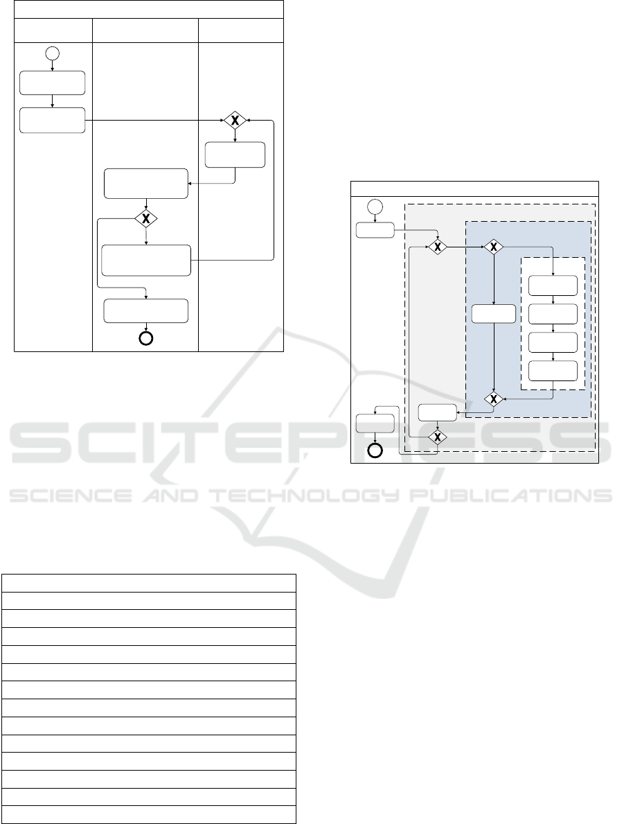
We elaborate business collaboration concerns
using the data query BPM depicted in Figure 2. The
BPM complies with the EPCIS specification, and is
considered the preferred scenario. However, many
food operators cannot support it. In the following, we
first describe the BPM and then state the
collaboration concern related to the model. The data
query BPM is initiated when an end-user takes a food
product—which can be input, semi-finished or end
product—at a food operator and requests
transparency data from the food operator’s ITS. For
the sake of simplicity we assume that each individual
food product item has a unique ID and the ID is
obtained by scanning the barcode of the product item.
The end-user obtains transparency data using a
barcode scanner or a smartphone application (End-
User App). Upon scanning a barcode, the end-user
app makes a query request and displays the
transparency data returned. When the end-user scans
a product item, the app requests transparency data
from the food operator (indicated as focal). The ITS
of the food operator determines where the product
data reside. If the data reside locally it fetches the
data from its own database; otherwise, it looks up the
service address of the food operator (indicated as
partner) that has the required data at a third-party
discovery service. It then makes a query request to
the partner food operator ITS, upon which the partner
ITS returns the data it has about the item. Since the
product may have passed through many food
operators—and since transparency data about the
ingredients are also part of the transparency data of a
Architecture Viewpoint for Modeling Business Collaboration Concerns using Workflow Patterns
29
product item—this process is repeated until no more
transparency data is desired or no more transparency
data can be obtained. The focal and partner food
operators are identical but drawn in two separate
lanes to be able to show the interactions among the
food operators clearly. Note, the focal food operator
lane represents the one food operator that received
the request from the end-user; the partner food
operator lane represents all other food operators
involved. After all data is gathered, the focal food
operator sends the aggregated data to the app, which
displays the data to the user.
Data Query Business Process
Scan
Product
End-User App
Food operator
(Focal )
Food operator
(Partner)
Lookup
Fetch Data
Format &
Display Data
Aggregate
Data
Fetch Data
Third party
(Discovery Service)
Discover
Service
(1)
(1)
(2)
(2)
Query
Figure 2: A BPM showing how transparency data is
queried across a food supply chain.
The BPM shown in Figure 2 has to be
implemented by all the four types of food operators
shown in Figure 1. The end-user app should also be
provided by the food operators. However, in practice,
many of the food operators do not support most of
the activities the BPM and cannot provide end-user
apps.
3.2 Problem Statement
In the previous sub-section we have described food
supply chains and illustrated an inherent business
collaboration concern they face regarding
transparency. In the case study we identified a
number of problems in aligning the BPMs
representing the preferred scenario and the software
systems that realistically can be realized by the
collaborating partners. Specifically, we can define
the following problems:
Difficulty in Realizing Collaboration Business
Processes
The elements of BPMs have to be supported by
businesses depending on their roles. That is, process
elements, such as, events, tasks and gateways have to
be realized by architectural elements, such as,
modules, components and nodes of the software
systems that are distributed across many businesses.
It turns out that the mapping of BPMs to the diverse
software systems is not straightforward. For example,
the BPM shown in Figure 2 spans many food
operators, many of which are, in practice, not capable
of fulfilling all the steps. Particularly, many of the
small food operators (mainly farmers) cannot afford
to deploy the required software systems.
Lack of a Common Model for Supporting the
Interaction Between Business Analyst and
Architects
Faced with the problem stated above business
analysts and software architects from the various
businesses come together to address the problem.
However, the two stakeholder types use two separate
sets of models hampering the communication
between them. Business analysts use BPMs to define
business processes. On the other hand, software
architects use architecture viewpoints that mainly
address concerns related to the structure of the
software system. For the given case study, it was
required early on to know which activities can be
fulfilled by which food operators. Neither the
business process models nor the software architecture
views provide this information. A common model
that depicts the business collaboration concerns (a
model that maps elements of BPMs to elements of
architectural design) would help to support the
communication and the design rationale.
Early Validation of the Business
Process-Architecture Alignment is Difficult
Too often BPMs are validated after the software
system is realized creating major risks. For example
the BPM of Figure 2 has an impact on the software
components that need to be deployed at each food
operator node. Given only this BPM and the
corresponding architectural designs, it is not easy to
validate that the two are aligned and feasible.
In light of the above obstacles we formulated the
following general research question: How can we
support software architects and business analysts to
design BPMs and the corresponding software
architecture as a team and minimize the mismatch
between the two designs?
ICSOFT-EA 2016 - 11th International Conference on Software Engineering and Applications
30
4 COLLABORATION
VIEWPOINT
Adapting the template for documenting architecture
viewpoints proposed in the ISO/IEC standard
mentioned before we propose a collaboration
viewpoint shown in Table 1. We describe the
viewpoint in detail in the following sub sections.
Viewpoint
Structural
Viewpoint
Software
Architect
Architecture
Stakeholder
Collaboration
Viewpoint
conforms
to
Collaboration
View
documented
using
frames
concerns of
Business
Analyst
*
uses
Business Process
Viewpoint
Workflow
Pattern
*
uses
*
uses
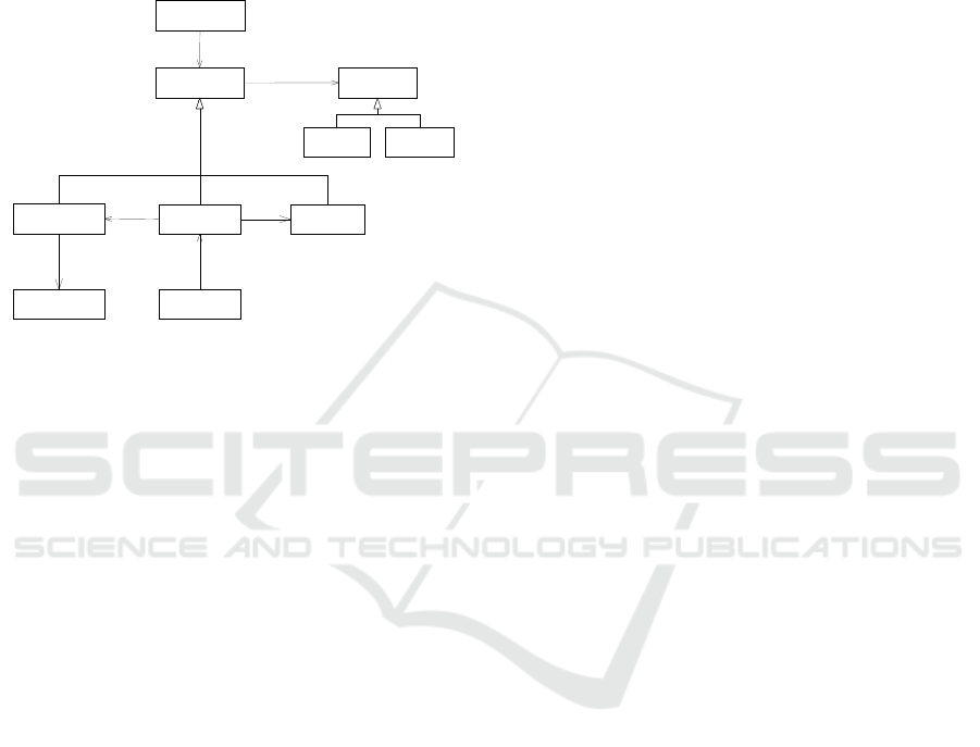
Figure 3: A metamodel for the collaboration view.
4.1 Metamodel
In Figure 3 we present a metamodel that describes
the concepts used in the collaboration viewpoint of
Table 1. The key stakeholders are identified as
software architects and business analysts.
Collaboration viewpoint is defined as a subtype of
viewpoint. Collaboration concerns are addressed in
collaboration views that conform to the collaboration
viewpoint.
4.2 Notations
The collaboration viewpoint uses elements from
business process and structural viewpoints. The
elements from the two viewpoints are described in
the following two sub sections; the models of the
viewpoint are described in the subsequent sub
sections.
4.2.1 BPMN
We adopt the BPMN modelling method to represent
BPMs (OMG 2011). BPMN is widely used among
business analysts and is also easily understandable
for software architects. BPMN models are used in
three ways. First, we consider the BPMs as models of
collaboration business processes. Second, we use
elements of the BPMN models in mapping tables
(see section 4.2.3). Third, we use fragments of BPMs
in workflow pattern diagrams (see section 4.2.4).
4.2.2 Architectural Design
We consider the models of C&C and allocations
views particularly relevant for the collaboration view.
These structural views are generally not fully
intelligible to business analysts. We, therefore,
consider only the elements of the models of these
structural views as modelling elements in the
mapping table. The architectural elements we
consider most relevant are components and nodes.
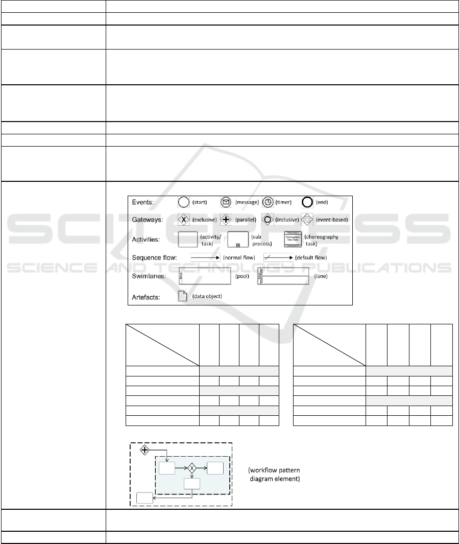
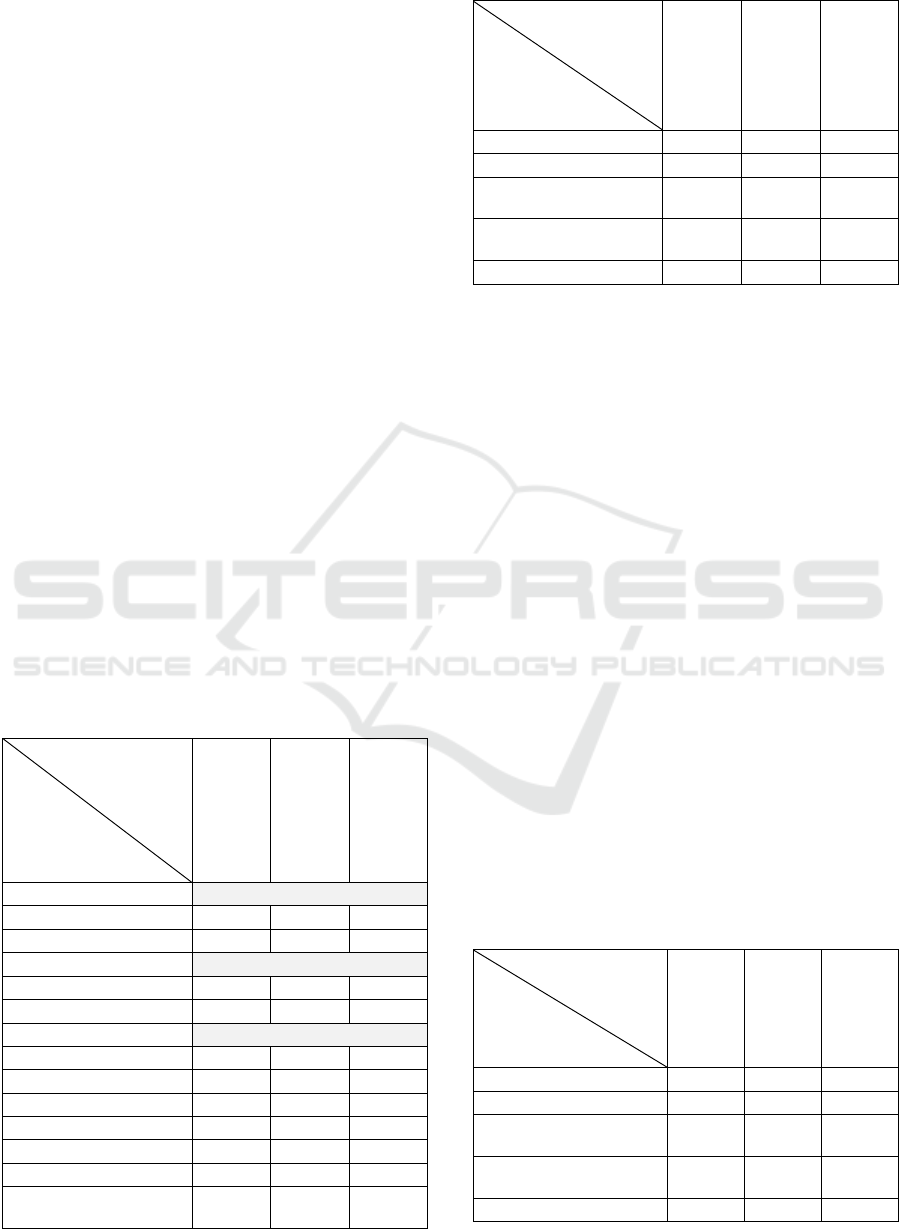
4.2.3 Mapping Tables
The mappings of business process and architectural
elements are made using two tables shown in Table
1:b. The first table captures how business process
elements are allocated across the collaborating
partners; the second table captures how architectural
elements are allocated across the collaborating
partners. The tables are used for both redesign and
validation purposes.
4.2.4 Workflow Design Diagram
Workflow patterns are represented using a workflow
pattern diagrams. In a workflow pattern diagram the
BPMN elements that belong to distinct workflow the
patterns are delineated using dashed-line blocks. To
delineate the BPMN elements the BPM diagram will
mostly require simplification. The creation and
application of workflow pattern diagram is
demonstrated in section 5.
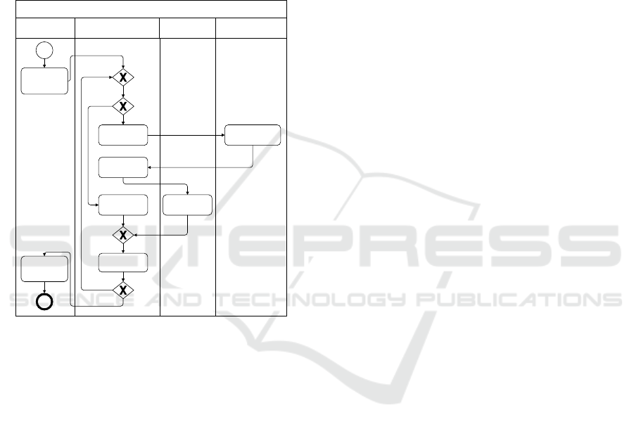
4.3 Method for Applying the Viewpoint
Figure 4 shows the method for applying the
collaboration viewpoint. The method is started by
business analysts; they design the initial BPMs in
step 1. In step 2 they identify the relevant workflow
patterns and draw workflow pattern diagrams for
each BPMs. The two steps are displayed sequentially
but, in reality, they are intertwined. Next, in step 3,
an iterative process of capturing the software
architecture, assessing alignment and redesigning of
both BPMs and architecture starts. This step is done
by software architects. In step 4 the business analysts
and the software architects work as a team to allocate
elements of the BPM and architectural designs to
collaborating partners using mapping tables. They
use the workflow pattern diagrams to facilitate the
allocation. In this step they identify misalignments
and determine if redesign is required. The next step,
step 5, depends on whether or not redesign is
required. If redesign is required the next step is to
redesign the BPMs and workflow pattern diagrams.
At this stage the mapping tables are used again to
Architecture Viewpoint for Modeling Business Collaboration Concerns using Workflow Patterns
31
reallocate elements to collaboration partners. We
consider the redesign of BPMs and workflow pattern
diagrams as the responsibility of the entire team
though the main responsivity rests on the business
analysts. After the redesign of BPMs and workflow
pattern diagrams the software architects redesign the
software architecture (step 3). If redesign is not
needed the BPMs, the workflow pattern diagrams
and the mapping tables are documented in
collaboration views following the documentation
outline proposed in the next sub section.
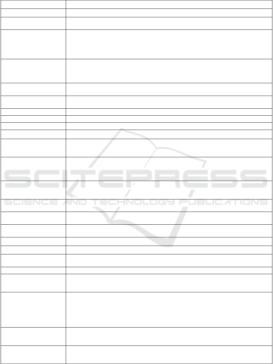
Table 1: Collaboration viewpoint documentation guide.
Viewpoint Element
Description
Name
Collaboration Viewpoint
Stakeholders
Business Analysts
Software Architects
Elements
Elements from OMG’s BPMN 2.0 specification
Elements from structural viewpoints (mainly Allocation and C&C viewpoints)
Workflow patterns
Relations
Maps to – defines the allocation of elements of BPMN models to collaborating partners
Maps to – defines the allocation of element of structure views to collaborating partners
Maps to – defines the allocation of elements of BPMN models to workflow patterns
Properties of Elements
Properties as defined in the structural viewpoints, BPMN specification, workflow patterns
Properties of Relations
Properties as defined in the structural viewpoints, BPMN specification, workflow patterns
Constraints
Constraints as defined in structural viewpoints, BPMN specification, workflow patterns
Each BPMN element should be mapped to a collaboration partner and a workflow
pattern
Notation
a) BPMN element notations*:
b) Mapping Tables:
Collaborating
partners
BPMN
Elements
Collaborating
partners
Structure
Elements
Events
Components
…
…
…
Activities
…
…
…
Nodes
Gateways
…
…
…
…
c) Workflow Pattern Diagram (dashed-line blocks represent a workflow pattern):
Relation to other
views/viewpoints
BPMN 2.0 specification, workflow patterns catalogue, allocation and C&C viewpoints.
Examples
See section V
* The list only widely used BPMN elements; for a complete list of BPMN elements refer to the OMG BPMN 2.0 specification (OMG 2011).
ICSOFT-EA 2016 - 11th International Conference on Software Engineering and Applications
32
Steps for Modeling a Collaboration View
Model Business
Processes
Business Analyst
Business Analyst &
Software Architect
Software Architect
Identify Workflow
Patterns
Map Models and Assess
Alignment
Redesign Business Process
Models and Workflow
Pattern Diagrams
Model Structural
Views
[alligned]
[not aligned]
Document the Software
Architecture
Figure 4: A process diagram representing the process of
modeling a collaboration view.
4.4 Documenting the Architecture
When documenting the software architecture the
collaboration views are described in detail after the
BPMs and the software architecture views are
presented. We propose the outline shown in Table 2
for documenting the software architecture.
Table 2: Overview of the software architecture document
including collaboration views.
1. Introduction
2. Documentation Roadmap
3. Business Process Models
4. Software Architecture Module Views
5. Software Architecture C&C Views
6. Software Architecture Allocation Views
7. Collaboration Views
7.1 Introduction
7.2 Workflow Patterns of BPMs
7.3 BPM-Organization Mappings
7.4 Architecture-Organization Mappings
7.5 Summary
8. Summary
9. Directory-Index, Glossary, Acronym List
5 APPLYING THE
COLLABORATION
VIEWPOINT
In this section we illustrate how the approach shown
in Figure 4 is applied in the real industrial case
mentioned in section 3. The first step of designing
the BPMs is already demonstrated in the BPM shown
in Figure 2. The second step is identifying the
workflow patterns. Figure 5 shows the workflow
cf-12 and cf-21
cf-4 and cf-5
cf-1
Workflow Pattern Diagram for the Data Query Business Process
Scan Product
Lookup
Fetch Data
Format &
Display Data
Aggregate
Data
Fetch Data
Discover Service
Query
Figure 5: A workflow pattern diagram for the query
business process model.
patterns of the BPM we identified. The workflow
patterns are: sequence (cf-1), exclusive choice (cf-4),
simple merge (cf-5), multiple instances without
synchronization (cf-12) and structured loop (cf-21).
A further analysis shows that the workflow patterns
cf-4 and cf-5 belong together. Similarly, the
workflow patterns cf-21 and cf-12 belong together.
Therefore, we identify three workflow patterns, two
of which are composite patterns.
The third step of the approach is to capture the
existing software architecture that is already in place.
For the sake of simplicity we distinguish between
two major groups of food operators in terms of their
existing software systems, i.e. their ITSs: small food
operator and large food operator. Similarly, we
identify three components of an ITS: a data query
component, a data aggregator component and a
product data retrieval service. In relation to the
business process shown in Figure 2 the data query
component implements the lookup and query tasks
and the 2
nd
XOR decision; the data aggregator
component implements the aggregate data task and
Architecture Viewpoint for Modeling Business Collaboration Concerns using Workflow Patterns
33
the 1
st
XOR decision; the data retrieval service
implements the fetch data task.
The next step, step 4, is mapping the allocation of
BPMs and architectural design elements to the
collaborating partners. Table 3 shows how currently
the BPM elements are supposed to be allocated
across the two types of food operators; Table 4 does
the same but for architectural elements instead of the
elements of the BPM. The tables are interpreted as
follows. A ‘+’ sign in a cell implies that the business
process or the architectural element is allocated to the
corresponding collaboration partners and the
collaboration partner indeed supports the element.
For instance, the scan product task should be
supported in large food operator nodes and it is
indeed supported. A ‘–’ sign implies that the business
process or the architectural element is allocated to the
collaboration partner but the collaboration partner
fails to support the element. Using the above
example, the scan product task should have been
supported by small food operator nodes but it is not.
An empty cell implies that the element is not relevant
for the specific collaboration partner. Typically, these
tables require knowledge of the state of affairs in all
collaboration partners, which could be many, and it
may require more than the simple +, – and empty
entries. As shown in the table, it turns out that small
food operators implement none of the required
architectural elements adequately and large food
operators provide only part, in this case only the
product data retrieval service structural element.
Table 3: Mapping of business process elements to the
corresponding collaborating partners.
Collaboration
partners
BPMN
Elements
Small Food
Operator
Large Food
Operator
Third party
Events
Start
-
+
End
-
+
Gateways
XOR {1}
-
-
XOR {2}
-
-
Tasks
Scan Product
-
+
Lookup
-
-
Discover Service
-
-
+
Query
-
-
Fetch Data
-
+
Aggregate Data
-
-
Format and Display
Data
-
+
Table 4: Mapping architectural elements to the
corresponding collaborating partners.
Collaboration
partners
Structure
Elements
Small Food
Operator
Large Food
Operator
Third party
End-User App
-
+
Query Component
-
-
Data Aggregator
Component
-
-
Product Data Retrieval
Service
-
+
Discovery Service
+
From the above tables it is clear that the desired
business processes are not aligned with the existing
architecture. The next step, step 5, is redesigning the
BPMs and workflow pattern diagrams; obviously a
new allocation is necessary for cases depicted in
Table 3 and Table 4. For instance, though small food
operators do not fulfill the allocated tasks, it turned
out that they are, however, willing to (and usually do)
delegate the tasks to third parties and pass the
required transparency data to them. Moreover, in the
food sector third-party transparency data repositories
are mandated by law as described in section 3.1. In
Table 5 we show the new allocation of architectural
elements to new collaborating partners, improving
the misalignment shown in Table 4. (Similarly, a new
allocation table for Table 3 can be produced but is
not included for brevity.) The new allocation allows
all food operators (small and large) to comply with
the EPCIS specification; but now a new
misalignment arises because the third party has yet to
support the newly allocated elements. It also raises an
issue related to data capture. Because small food
operators have to pass transparency data to a third-
party, the data capture (which so far was local and
trivial) is now a collaboration concern.
Table 5: New allocation of architectural elements to
collaborating partners.
Collaboration
partners
Structure
Elements
Small Food
Operator
Large Food
Operator
Third party
End-User App
-
Query Component
-
Data Aggregator
Component
-
Product Data Retrieval
Service
+
-
Discovery Service
+
ICSOFT-EA 2016 - 11th International Conference on Software Engineering and Applications
34
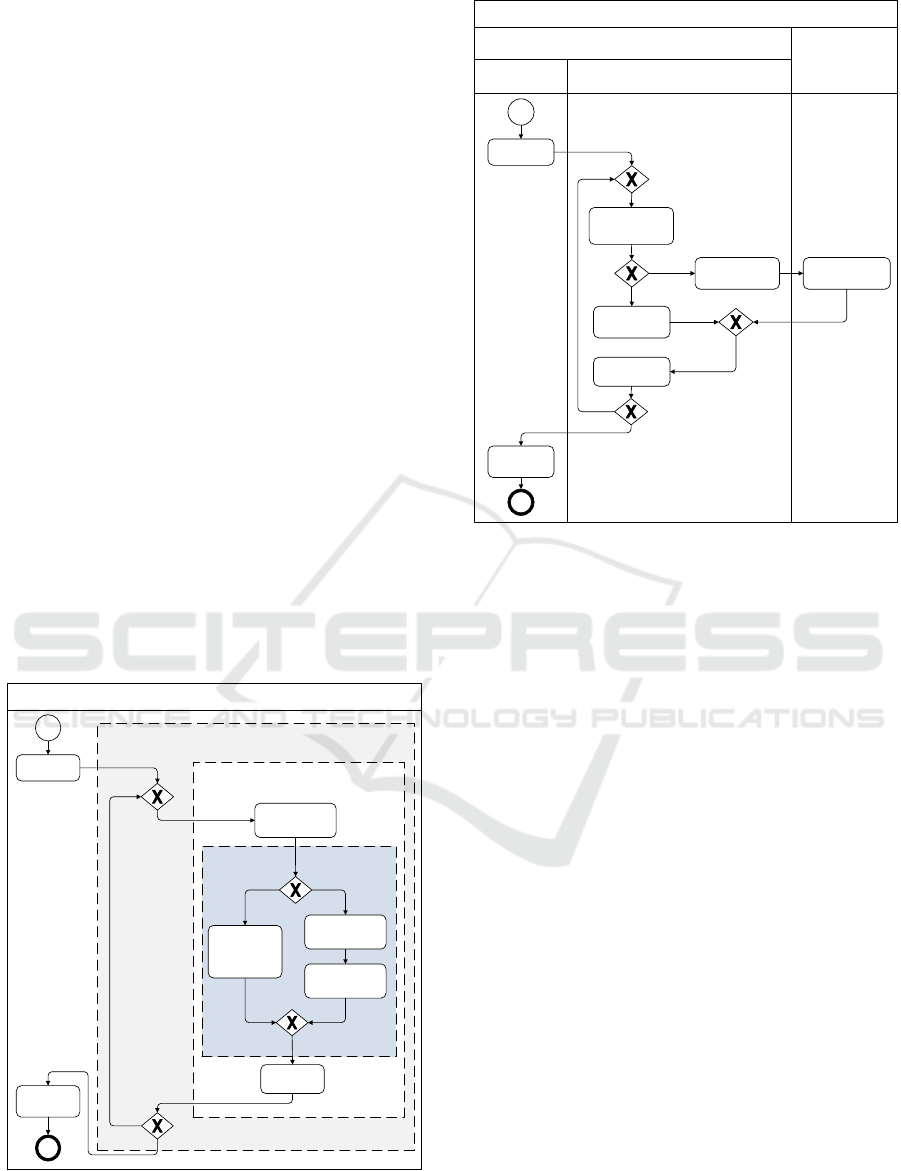
As part of step 5 workflow pattern diagram are
used to redesign the BPMs (which is the opposite of
what is done in step 2). Unlike in step 2 we
(re)design the workflow pattern diagrams first and
then we apply them to (re)designing the BPMs.
We start the redesign process with the workflow
pattern diagram because the workflow patterns
identified earlier seem to capture the fundamental
essence of the query BPM and may not need
modifications. The BPM, on the other hand, may
change substantially. In Figure 6 we provide the
improved workflow pattern diagram that contains the
same three workflow patterns but in a different
configuration. The change in the configuration of the
workflow patterns is a direct consequence of the new
allocation. The details of the consequences of the
new allocation are shown in the new BPM provided
in Figure 7. As in the previous business process the
new business process is triggered by the end-user app
but all query requests are always sent to the third
party. Instead of all food operators, the new model
involves only large food operators in the query
business process. Small food operators no longer
need to maintain their own transparency data and to
support the fetch data task, because the third-party
supports this task on their behalf. When these and
other redesign issues are resolved the software
architects (re)design the software architecture by
going back to step 4.
cf-12 and cf-21
cf-1
cf-4 and cf-5
Workflow Pattern Diagram for the Data Query Business Process
Scan Product
Fetch Data
from Shared
Repository
Format &
Display Data
Aggregate
Data
Fetch Data from
Food Operator
Discover Service
Query
Figure 6: Improved workflow pattern diagram for guiding
the design of an improved query BPM.
Data Query Business Process
Scan Product
End-User App
Third party
Fetch Data
Format &
Display Data
Aggregate Data
Food Operator
(Large)
Discover Service
{1}
{1}
Fetch Data
{2}
Query
{2}
Discovery & Shared Repository Service
Figure 7: Improved query business process model.
6 RELATED WORK
The prominent way addressing business processes
and software architecture concerns along with other
concerns, such as general vision for the system,
concerns related to technology, etc. in a consistent
manner is to follow guidance provided by an
enterprise architecture framework. The Zachman
(Rational Software 2001) and TOGAF/ArchiMate
(The Open Group 2013) frameworks are probably the
most widely used and include the modeling of
business processes and the designing of software
architecture as part of the larger enterprise
architecture. These framework use largely fixed
categories of perspectives and concerns (e.g. vision,
business concerns, software architecture concerns,
etc.) Moreover, they follow a hierarchical
conceptualization of models in which requirements
cascade from vision, to BPMs, to software
architecture and finally to technology architecture. A
hierarchical approach suggests the use of elaborate
methods to get the design at a higher hierarchical
level before moving to the next. There are for
instance extensive methods for analyzing the as-is
BPMs and designing elaborate to-be BPMs (Sharp
and McDermott 2009) before a large scale
architectural design process commences. These
approaches do not directly address business
Architecture Viewpoint for Modeling Business Collaboration Concerns using Workflow Patterns
35

collaboration concerns that often arise when different
organizations are involved.
Business collaboration concerns could probably
be addressed generically as cross cutting quality
concerns across different viewpoints. In this respect
business collaboration concerns could be viewed as
concerns that cut across business process and
architecture viewpoints. In this regard the concept of
architectural perspectives is suggested that include a
collection of activities, tactics and guidelines to be
used across a number of the architectural views to
address quality concerns (Woods and Rozanski
2005). In this context, Rozanski and Wood define
several architectural perspectives for selected quality
concerns such as security, performance, scalability,
availability and evolution. In order to capture the
system-wide quality concerns, each relevant
perspective is applied to some or all views. In this
way, the architectural views provide the description
of the architecture, while the architectural
perspectives can help to analyze and modify the
architecture to ensure that system exhibits the desired
quality properties. However, no architectural
perspective for addressing business collaboration
concerns has been addressed yet. Since business
collaboration is not cross cutting concern in many
other viewpoints than the ones we considered we
have chosen for defining an explicit viewpoint for the
business collaboration concern.
Architecture consistency analysis has been
mainly investigated in relation to consistency
between software code and software architecture.
Hereby, architecture consistency implies that the
architecture design elements can be mapped to the
implementation elements. In case the relationships
between the architecture and implementation do not
correspond then these are called architectural
violations. If the relations that are present in the
architecture are also found in the implementation
then this is convergent relation. In case the
architecture relation is not present in the
implementation then this is called an absence
relation. A successful design recovery technique that
is used for architecture consistency checking is the
reflexion modeling approach as proposed by Murphy
et al. (Murphy et al. 2001). In this paper we have also
focused on consistency of the architecture but now
from a business model perspective in which we
focused on business collaboration concerns.
Business collaboration concerns are also
addressed as business process choreography – as
opposed to business process orchestration. In this
respect recent research show that it is possible to
automate the generation software from business
processes choreography models (Autili et al. 2015).
Such an approach do not, however, constraints that
are imposed on business process choreography
models by the software architecture.
7 CONCLUSIONS
Traditionally business analysts and software
architects address collaboration concerns separately
which often leads to a misalignment between the
business process and architecture. This problem is to
an extent manageable in the context of an individual
organization though a careful design of the business
processes before proceeding with the design of the
software architecture. This approach is however not
feasible when considering collaboration concerns that
involve multiple organizations. In this context, we
have identified three key collaboration concerns:
ensuring that the BPMs are indeed supported by
software components, ensuring that business analyst
can communicate effectively with software architects
in search of better design solutions, and validating
the architecture with respect to the BPMs.
To cope with these problems we have proposed
the architecture collaboration viewpoint that supports
the communication between the business analysts
and architects, and that helps to align the business
process models and the software architecture of the
collaboration system. The viewpoint has been
applied for a real industrial case study on food supply
chains. The business collaboration concerns that are
discussed in this paper and experienced within case
study were addressed using the collaboration
viewpoint.
ACKNOWLEDGEMENT
The research leading to this paper received funding
from the European Community's Seventh Framework
Program (FP7/2007-2013) within the FI-PPP’s
project FIspace under grant agreement n° 604 123.
The authors acknowledge the individuals and
companies involved for their support and the
European Community for their funding.
REFERENCES
Autili, M., P. Inverardi and M. Tivoli (2015). "Automated
Synthesis of Service Choreographies." IEEE Software
32(1): 50-57.
Aversano, L., C. Grasso and M. Tortorella (2016).
"Managing the alignment between business processes
ICSOFT-EA 2016 - 11th International Conference on Software Engineering and Applications
36

and software systems." Information and Software
Technology 72: 171-188.
Avison, D., J. Jones, P. Powell and D. Wilson (2004).
"Using and validating the strategic alignment model."
The Journal of Strategic Information Systems 13(3):
223-246.
Bartens, Y., F. Schulte, Vo, x00Df and S. (2014). E-
Business IT Governance Revisited: An Attempt
towards Outlining a Novel Bi-directional Business/IT
Alignment in COBIT5. System Sciences (HICSS),
2014 47th Hawaii International Conference on.
Clements, P., F. Bachmann, L. Bass, D. Garlan, J. Ivers,
R. Little, P. Merson, R. Nord and J. Stafford (2010).
Documenting software architectures: views and
beyond, Addison-Wesley.
Davenport, T. H. and J. E. Short (1998). "The new
industrial engineering: information technology and
business process redesign." IEEE Engineering
Management Review 26(3): 46-60.
Dumas, M., M. La Rosa, J. Mendling and H. Reijers
(2013). Introduction to Business Process Management.
Fundamentals of Business Process Management,
Springer Berlin Heidelberg: 1-31.
EC (2000). "Regulation (EC) No 1760/2000 of the
European Parliament and of the Council of 17 July
2000 establishing a system for the identification and
registration of bovine animals and regarding the
labelling of beef and beef productsand repealing
Council Regulation (EC) No 820/97." Official Journal
of the European Communities (L 204): 1-10.
EC (2002). "Regulation (EC) No 178/2002 of the
European Parliament and of the Council of 28 January
2002 laying down the general principles and
requirements of food law, establishing the European
Food Safety Authority and laying down procedures in
matters of food safety." Official Journal of the
European Communities L 31(1): 1-24.
EC (2004). "Regulation No. 911/2004 of 29 April 2004
implementing Regulation (EC) No 1760/2000 of the
European Parliament and of the Council as regards
eartags, passports and holding registers." Official
Journal of the European Union L 163: 65-70.
EC (2007). Factsheet: Tracing food through the production
and distribution chain to identify and address risks and
protect public health. Brussels.
EC (2011). "Commission Implementing Regulation (EU)
No 931/2011 of 19 September 2011 on the traceability
requirements set by Regulation (EC) No 178/2002 of
the European Parliament and of the Council for food
of animal origin." Official Journal of the European
Union L 242: 1-2.
EC (2015). "Regulation (EU) No 2015/262 of 17 February
2015 laying down rules pursuant to Council Directives
90/427/EEC and 2009/156/EC as regards the methods
for the identification of equidae (Equine Passport
Regulation)." Official Journal of the European Union
(L 59): 51.
EPCglobal (2014). EPC Information Services (EPCIS)
Version 1.1 Specification. GS1 Standard Version 1.1,
May 2014. Brussels, Belgium, GS1 AISBL.
GS1 (2015). GS1 General Specifications. Version 15
(issue 2), Jan-2015, GS1: 490.
Hofmeister, C., R. Nord and D. Soni (2000). Applied
software architecture, Addison-Wesley Professional.
Hong-Mei, C. (2008). Towards Service Engineering:
Service Orientation and Business-IT Alignment.
Hawaii International Conference on System Sciences,
Proceedings of the 41st Annual.
ISO/IEC/IEEE (2011). Systems and software engineering
-- Architecture description. ISO/IEC/IEEE Standard
42010:2011.
Kruchten, P. (2004). The rational unified process: an
introduction, Addison-Wesley Professional.
Kruchten, P. B. (1995). "The 4+1 View Model of
architecture." Software, IEEE 12(6): 42-50.
Lattanze, A. J. (2008). Architecting Software Intensive
Systems: A Practitioners Guide, CRC Press.
Murphy, G. C., D. Notkin and K. J. Sullivan (2001).
"Software reflexion models: bridging the gap between
design and implementation." Software Engineering,
IEEE Transactions on 27(4): 364-380.
OMG (2011). Business Process Model and Notation 2.0
(BPMN 2.0).
Rational Software (2001). The Zachman framework for
enterprise architecture and Rational best practices and
products, a Rational Software White paper, http://ww
w.rational.com/.
Russell, N., W. M. van der Aalst and N. Mulyar (2006).
"Workflow Control-Flow Patterns: A Revised View."
BPM Center Report BPM-06-22.
Sharp, A. and P. McDermott (2009). Workflow modeling:
tools for process improvement and applications
development, Artech House.
Tekinerdogan, B. (2014). Software Architecture.
Computing Handbook, Third Edition, Chapman and
Hall/CRC: 1-16.
The Open Group (2013). ArchiMate 2.1 Specification
(http://pubs.opengroup.org/architecture/archimate2-do
c/toc.html).
van der Aalst, W. M. P. and A. ter Hofstede. (2011).
"Workflow Patterns. http://www.workflowpatterns.
com/." Retrieved December 23, 2015.
Van der Aalst, W. M. P., A. H. M. Ter Hofstede, B.
Kiepuszewski and A. P. Barros (2003). "Workflow
Patterns." Distributed and Parallel Databases 14(1):
5-51.
Verdouw, C., A. Beulens and S. Wolfert (2014). Towards
Software Mass Customization for Business
Collaboration. Global Conference (SRII), 2014 Annual
SRII.
Woods, E. and N. Rozanski (2005). Using Architectural
Perspectives. Software Architecture, 2005. WICSA
2005. 5th Working IEEE/IFIP Conference on.
Architecture Viewpoint for Modeling Business Collaboration Concerns using Workflow Patterns
37
APPENDIX A – WORKFLOW PATTERNS
Pattern Categories
Patterns*
Control-Flow (CF)
Basic
Sequence (cf-1), Parallel Split (cf-2), Synchronization (cf-3), Exclusive Choice (cf-4), Simple Merge (cf-
5)
Advanced Branching and
Synchronization
Multi-Choice (cf-6), Structured Synchronizing Merge (cf-7), Multi-Merge (cf-8), Structured
Discriminator (cf-9), Blocking Discriminator (cf-28), Cancelling Discriminator (cf-29), Structured Partial
Join (cf-30), Blocking Partial Join (cf-31), Cancelling Partial Join (cf-32), Generalized AND-Join (cf-33),
Local Synchronizing Merge (cf-37), General Synchronizing Merge (cf-38), Thread Merge (cf-41), Thread
Split (cf-42)
Multiple Instance
Multiple Instances without Synchronization (cf-12), Multiple Instances with a Priori Design-Time
Knowledge (cf-13), Multiple Instances with a Priori Run-Time Knowledge (cf-14), Multiple Instances
without a Priori Run-Time Knowledge (cf-15), Static Partial Join for Multiple Instances (cf-34),
Cancelling Partial Join for Multiple Instances (cf-35), Dynamic Partial Join for Multiple Instances (cf-36)
State-based
Deferred Choice (cf-16), Interleaved Parallel Routing (cf-17), Milestone (cf-18), Critical Section (cf-39),
Interleaved Routing (cf-40)
Cancellation and Force
Completion
Cancel Task (cf-19), Cancel Case (cf-20), Cancel Region (cf-25), Cancel Multiple Instance Activity (cf-
26), Complete Multiple Instance Activity (cf-27)
Iteration
Arbitrary Cycles (cf-10), Structured Loop (cf-21), Recursion (cf-22)
Termination
Implicit Termination (cf-11), Explicit Termination (cf-43)
Trigger
Transient Trigger (cf-23), Persistent Trigger (cf-24)
Resource-Flow (RF)
Creation
Direct Distribution (rf-1), Role-Based Distribution (rf-2), Deferred Distribution (rf-3), Authorization (rf-
4), Separation of Duties (rf-5), Case Handling (rf-6), Retain Familiar (rf-7), Capability-Based Distribution
(rf-8), History-Based Distribution (rf-9), Organizational Distribution (rf-10), Automatic Execution (rf-11)
Push
Distribution by Offer - Single Resource (rf-12), Distribution by Offer - Multiple Resources (rf-13),
Distribution by Allocation - Single Resource (rf-14), Random Allocation (rf-15), Round Robin Allocation
(rf-16), Shortest Queue (rf-17), Early Distribution (rf-18), Distribution on Enablement (rf-19), Late
Distribution (rf-20)
Pull
Resource-Initiated Allocation (rf-21), Resource-Initiated Execution - Allocated Work Item (rf-22),
Resource-Initiated Execution - Offered Work Item (rf-23), System-Determined Work Queue Content (rf-
24), Resource-Determined Work Queue Content (rf-25), Selection Autonomy (rf-26)
Detour
Delegation (rf-27), Escalation (rf-28), Deallocation (rf-29), Stateful Reallocation (rf-30), Stateless
Reallocation (rf-31), Suspension-Resumption (rf-32), Skip (rf-33), Redo (rf-34), Pre-Do (rf-35)
Auto-start
Commencement on Creation (rf-36), Commencement on Allocation (rf-37), Piled Execution (rf-38),
Chained Execution (rf-39)
Visibility
Configurable Unallocated Work Item Visibility (rf-40), Configurable Allocated Work Item Visibility (rf-
41)
Multiple Resource
Simultaneous Execution (rf-42), Additional Resources (rf-43)
Data-Flow (DF)
Data Visibility
Task Data (df-1), Block Data (df-2), Scope Data, Multiple Instance Data (df-4), Case Data (df-5), Folder
Data (df-6), Workflow Data (df-7), Environment Data (df-8)
Data Interaction
Internal Data Interaction
Task to Task (df-9), Block Task to Sub-Workflow Decomposition (df-10), Sub-Workflow Decomposition
to Block Task (df-11), To Multiple Instance Task (df-12), From Multiple Instance Task (df-13), Case to
Case (df-14)
External Data
Interaction
Task to Environment - Push-Oriented (df-15), Environment to Task - Pull-Oriented (df-16), Environment
to Task - Push-Oriented (df-17), Task to Environment - Pull-Oriented (df-18), Case to Environment -
Push-Oriented (df-19), Environment to Case - Pull-Oriented (df-20), Environment to Case - Push-
Oriented (df-21), Case to Environment - Pull-Oriented (df-22), Workflow to Environment - Push-
Oriented (df-23), Environment to Workflow - Pull-Oriented (df-24), Environment to Workflow - Push-
Oriented (df-25), Workflow to Environment - Pull-Oriented (df-26)
Data Transfer
Data Transfer by Value - Incoming (df-27), Data Transfer by Value - Outgoing (df-28), Data Transfer -
Copy In/Copy Out (df-29), Data Transfer by Reference - Unlocked (df-30), Data Transfer by Reference -
With Lock (df-31), Data Transformation - Input (df-32), Data Transformation - Output (df-33)
Data-based Routing
Task Precondition - Data Existence (df-34), Task Precondition - Data Value (df-35), Task Postcondition -
Data Existence (df-36), Task Postcondition - Data Value (df-37), Event-based Task Trigger (df-38), Data-
based Task Trigger (df-39), Data-based Routing (df-40)
* The names of the patterns are shortened; the pattern ID’s (numbers between brackets) are original (van der Aalst and ter Hofstede 2011).
ICSOFT-EA 2016 - 11th International Conference on Software Engineering and Applications
38
