
Towards a User-wheelchair Shared Control Paradigm for Individuals
with Severe Motor Impairments
Alfredo Ch
´
avez Plascencia and Jaroslav Rozman
Faculty of Information Technology, IT4Innovations Centre of Excellence, Brno University of Technology,
Bo
ˇ
zet
ˇ
echova 1/2 612 66, Brno, Czech Republic
Keywords:
Assistive Technology, Sensor Fusion, Autonomous Wheelchair.
Abstract:
This paper presents a work in progress study of a novel user-wheelchair shared control paradigm for individu-
als with severe motor impairments, which consists of an optimal distribution between several modes, from full
user control up to autonomous driving one. To this end, a C400 Permobil wheelchair has been equipped with
a control command communication interface and with a scanning laser and a RGB-D sensors to carry out the
automation algorithms that are part of the robot operating system (ROS) framework. Moreover, sensor data
fusion for map making based on the Bayesian method is applied to the Xtion Pro Live RGB-D camera and the
Hokuyo laser sensor data readings. These latter are interpreted by a probabilistic heuristic model that abstracts
the beam into a ray casting to an occupied grid cell. Preliminary pilot tests were performed in two different
room shapes. The first one in a two room laboratory with a narrow doorway, and the second one in a corri-
dor. The former experiment was dropped due to failure to success, whereas, the latter was a successful one.
This has been tested with three different modalities; hand-joystick, tongue-joystick and autonomous modes
respectively. The successful results of the second pilot-test have proven the feasibility of using a combina-
tion of autonomous and manual control of a powered wheelchair in order to continue development towards a
shared-control paradigm.
1 INTRODUCTION
Powered wheelchairs (PWC) are used to assist mobil-
ity of individuals with severe motor disabilities, such
as those with tetraplegia. Users that still maintain
some degree of motor control of arms or hands use a
joystick in order to control the direction and speed of
the PWC. On the other hand, users with more severe
or complete motor disabilities have to rely on alter-
native control interfaces that can detect head move-
ment (Christensen and Garcia, 2003), chin move-
ment (Cooper et al., 2002), gaze (San Agustin et al.,
2009), tongue movement (Xueliang and Maysam,
2010) (Lund et al., 2010) and even forehead muscular
activity and brain waves (Torsten, Felzer and Rainer,
Nordman, 2007). Thus, research has been done to de-
velop devices that can interface the remaining func-
tional parts of such individuals. Many of these inter-
faces require the user to sustain high levels of con-
centration for navigating in environments with many
obstacles. Some systems might be tedious and tire-
some to use, especially when constantly maneuver-
ing a wheelchair, while others might interfere with
the normal use of the user’s vision or head, eyes or
tongue movement. Allowing certain degree of au-
tonomy to the wheelchair might relieve the users of
the burden of long periods of concentration or fatigue,
and allow a more free use of their own eyes, tongue or
head movement while driving the wheelchair. How-
ever, a fully autonomous system is not desired, since
the users should be allowed as much control of the
wheelchair as their capabilities and degree of disabil-
ity allows them to have, and without compromising
the use of their vision, speech head movement unnec-
essarily or for prolonged periods of time.
Some related research work has been focused on
sharing the wheelchair control with the user. For in-
stance, a shared wheelchair control method for ob-
stacle avoidance is presented in (Petry et al., 2010).
This method mainly proposes using potential field for
path planning and shares the wheelchair control to
help the user to avoid obstacles. (Faria et al., 2013)
presents a manual-shared-automatic method for con-
trolling a PWC. The automatic control consists of fol-
lowing points without human intervention, the shared
control acts in safety situations, mainly when there
246
Plascencia, A. and Rozman, J.
Towards a User-wheelchair Shared Control Paradigm for Individuals with Severe Motor Impairments.
DOI: 10.5220/0005973302460253
In Proceedings of the 13th International Conference on Informatics in Control, Automation and Robotics (ICINCO 2016) - Volume 2, pages 246-253
ISBN: 978-989-758-198-4
Copyright
c
2016 by SCITEPRESS – Science and Technology Publications, Lda. All rights reserved
is a potential collision. (Jiding et al., 2014) presents
a shared-control wheelchair based on Brain Computer
Interface (BCI), where the shared-control provides as-
sistance strategy to control the wheelchair when it is
in a collision region.
Based on the present research our main goal
is to investigate further in order to find the opti-
mal distribution of control tasks between the user
and the intelligent wheelchair controller. This shall
help to develop a novel user-wheelchair shared con-
trol paradigm that takes into consideration the needs
and abilities of individuals with severe motor impair-
ments, and allows them to control a PWC from a
user-controlled, through a semi-autonomous up to a
fully autonomous way. The amount of autonomy in
the semi-autonomous control mode, also referred to
as ”shared-control”, should depend on the user pref-
erences, the degree of disability of the user and the
amount of input the user can give in a fast and ef-
ficient way, allowing the user and the wheelchair to
”share” control tasks.
For this study, two different environment shapes
were taken into account in order to validate the pre-
liminary paradigm. The first shape is a two room lab-
oratory and the second one is a corridor. The exper-
iments of the first shape were dropped early due to
failure to success and are not presented in this arti-
cle. Instead an analysis on how to overcome them is
presented in the conclusion. On the other hand, the
second pilot tests were successful and are presented
in this work.
From the alternative control interfaces for a PWC,
we have chosen to use a tongue-controlled inter-
face. Using the tongue to control a PWC seems to
be a promising alternative for the following reasons.
Firstly, the tongue is able to perform sophisticated
motor control and manipulation tasks with many de-
grees of freedom. Secondly, it is able to move rapidly
and accurately and does not fatigue easily and can be
controlled naturally without requiring too much con-
centration. Georgia Institute of Technology has de-
veloped a tongue drive system (TDS) that consists of
a headset and a magnetic tongue barbell. Through a
smartphone (iPhone), the TDS is able to interpret five
tongue movement commands: forward (FD), back-
ward (BD), turning right (TR), left (TL) and stopping
(N) (Jeonghee et al., 2008), (Xueliang and Maysam,
2010), (Andreasen, 2006),(Jeonghee et al., 2012).
Similarly, an intra-oral inductive tongue control sys-
tem (ITCS) has been designed and built at Aalborg
University. It interpolates the sensor signals to em-
ulate an intra-oral touchpad that can proportionally
control the direction and speed of the PWC (Caltenco
et al., 2011).
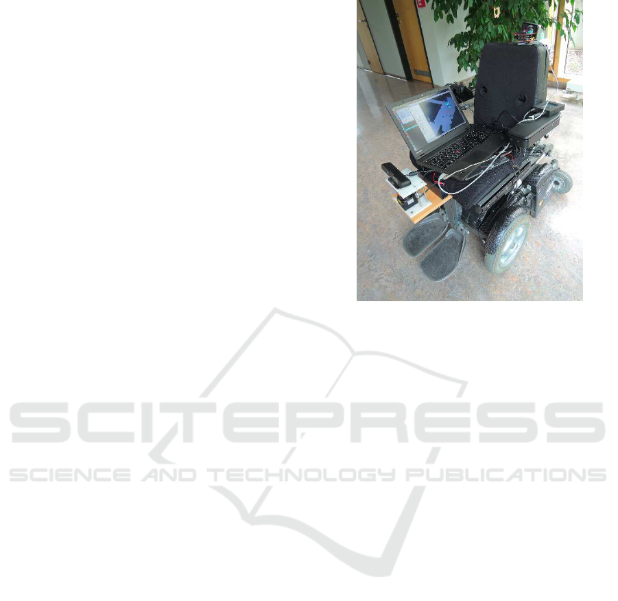
Figure 1: The C400 permobil wheelchair equipped with a
control command communication interface and with a scan-
ning laser and a RGB-D sensors.
2 SYSTEM DESCRIPTION
2.1 Communication Interface
The C400 Permobil PWC as shown in Figue 1 comes
with an Easy Rider wheelchair interface, from HMC
International, an Easy Rider display unit and a joy-
stick. The standard joystick mode accepts as input
signals a reference value of 5V and two analog volt-
age values in the range of 4V to 6V to proportionally
move the PWC from right to left and from back to
forward. To this end, an interface to send velocity
control commands (VCC) from the computer to the
motors has been developed using an Arduino UNO
board. The Arduino board receives two VCC bytes
(one for left-right and one for forward-backward di-
rections) and generates two pulse width modulated
(PWM) signals in the range of 0 to 5V. The signals
are converted to analog voltage using a simple RC
low-pass filter and stepped-up using a single supply
non-inverting DC Summing Amplifier. The resulting
voltage is used to emulate the analog joystick posi-
tion as an input to the Easy Rider interface. The Easy
Rider interface then sends the necessary control sig-
nals to the wheelchair’s motor controller.
2.2 Alternative Control Interface
The ITCS (Caltenco et al., 2011), consists of two sep-
arate parts, the intra-oral device and an external con-
Towards a User-wheelchair Shared Control Paradigm for Individuals with Severe Motor Impairments
247
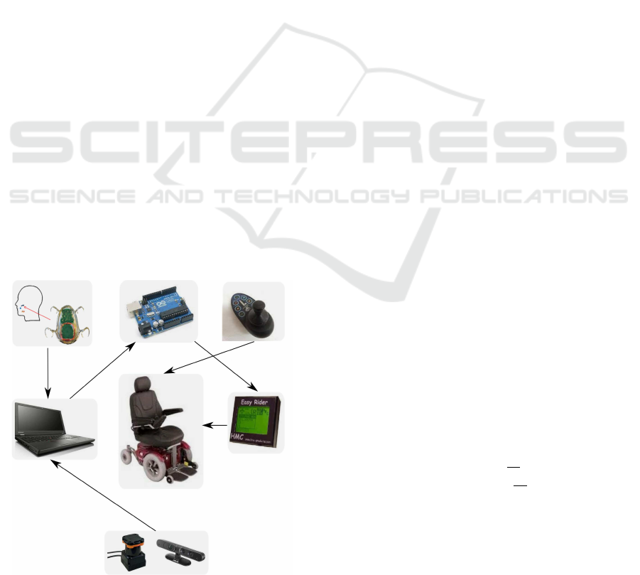
troller. The intra-oral device detects tongue move-
ments and wirelessly transmit signals to the external
controller, which connects to the Easy Rider inter-
face via the Joystick Input and to the computer via
bluetooth. The ITCS’s external controller interprets
and process tongue movement signals and transforms
them into joystick or mouse commands that can be
sent to the wheelchair or the computer. The com-
puter is a Lenovo T540p with an Intel(R) Core(TM)
i5-4200M CPU @ 2.50GHz running Ubuntu 12.04
(precise), The system previously explained can be de-
picted in Figure 2.
2.3 Sensors
Data from the environment is obtained by a Hokuyo
UTM-30LX scanning laser range finder. It has a sens-
ing range from 0.1m to 30m. Measurement accuracy
is within 3mm tolerance up to 10m of the sensor’s
range. The scanning rate is 25 milliseconds across a
270 range.
The Asus Live Xtion Pro RGB-D camera, popular
in various robotic projects. It has a field of view of
58
◦
H, 45
◦
V (Horizontal, Vertical). Meanwhile, the
sensor’s depth image size is 640 × 480 pixels with
a total of 307, 200 pixels. The distance of use of the
sensor is between 0.8m and 3.5m.
3 SENSOR FUSION AND
MODELS
The laser can measure the distance to an object quite
accurately. However, there is an uncertainty in the
Figure 2: Overview of the System.
pulse that is reflected back to the sensor. On the other
hand, the RGB-D sensor also returns the depth to each
pixel, which uncertainty also need to be modeled. The
approach taken by (Moravec and Elfes, 1985), (Elfes,
1989b) and (St
ˇ
ep
´
an et al., 2005) to model the oc-
cupied and empty regions of the sonar beam can be
taken into consideration to model the uncertainty in
both sensors data readings.
RGB-D and laser probabilistic sensor data fusion
is proposed to complement both sensors field of view,
(Ch
´
avez and Karstoft, 2014). Thus, Elfes (Elfes,
1989a) has proposed in his previous work the use of a
recursive Bayes formula to update the occupancy grid
for multiple sensor observations.
4 SOFTWARE ARCHITECTURE
Robot operating system (ROS) (Quigley et al., 2009)
is proposed as the software architecture to achieve
the different modes the user can select to drive the
PWC. The navigation stack (NS), which is a set of
configurable nodes, has been configured properly to
the shape and dynamics of the PWC to be performed
at a high level. Broadly speaking, the heart of the nav-
igation stack is the move base node which provides
a high level interface between odometer, PWC base
controller, sensors, sensor transforms, map server and
monte carlo localization algorithm (AMCL) nodes to
the local and global planners.
5 METHODS
One participant with no previous experience driving
a PWC participated in this pilot study. To this end, a
5 × 2 × 2 factorial experiment has been designed with
the following factors (independent variables):
1. Control mode [M] with five levels:
• M
A
(autonomous-mode)
• M
JG
(user-mode using a usb gamepad joystick)
• M
JW
(user-mode using wheelchair’s joystick)
• M
JT
(user-mode using tongue-joystick)
2. Wheelchair velocity [V ] with two levels:
• V
L
(low velocity, 0.186
m
sec
)
• V
H
(high velocity, 0.243
m
sec
)
3. Number of obstacles [O] with two levels:
• O
F
(few obstacles on the path, 5 obstacles)
• O
P
(plenty obstacles on the path, 10 obstacles )
Moreover, the following dependent variables are
used to compare performance of each test scenario:
ICINCO 2016 - 13th International Conference on Informatics in Control, Automation and Robotics
248
1. T
P
(path’s completion time)
2. V
A
(average velocity)
3. N
C
(number of collisions)
4. d
p
(path’s distance).
The experiment design is three-dimensional in the
within subject variables. However, it is not fully fac-
torial, since the tongue-joystick control mode (M
JT
)
did not perform the experiment using different veloc-
ity conditions [V ], giving a total of 18 within subject
conditions, instead of 20.
A graphical user interface (GUI) has been imple-
mented, where three modes can be selected by the op-
erator.
• Joystick mode (M
J
), the PWC is able to be ma-
nipulated by the commands emulated from the
control level, e.g. forward (F), backward (B),
right (R), left (L) and stopping (S). This can be
done using any of the three control interfaces
(wheelchair joystick (M
JW
), gamepad joystick
(M
JG
)or tongue joystick (M
JT
)).
• Semi-autonomous mode (M
S
), The process is
comprise of the following steps; 1.- Real obsta-
cles have been placed in the environment. 2.- A
global map with no obstacles is used. 3.- Joystick
mode is applied in order for the user to rotate the
PWC left or right while trying to find a suitable
path. And, once this path has been spotted the user
can select the (F) joystick command. 3.- Then, a
shared-control algorithm is activated that finds a
suitable goal in the desired direction at the end of
the map. 4.- Afterwrads, the NS uses this goal
to move the PWC towards that direction avoiding
obstacles on its way till either the user cancel the
action or the PWC reaches the goal coordinates.
• Autonomous mode (M
A
), the user selects the co-
ordinates of a destination point on a map of the
known environment using the ITCS. The user can
always be able to override autonomous control
and take control of the wheelchair at any moment.
The C400 Permobil wheelchair serves as experimen-
tal testbed. The tests were carried out with real data
in an indoor laboratory environment. To this end, the
map of the indoor environment was built prior to the
tests, this was achieved by using the fused Hokuyo
laser and RGB-D data, which have been placed in
front of the PWC.
The RGB-D catches 3D depth data that is pro-
jected into 2D to ease the integration process. At the
same time, the laser field of view also catches 2D
depth data. Furthermore, sensor registration is used
to align both sensor readings, so they can not suffer
from misalignment that can potentially cause errors
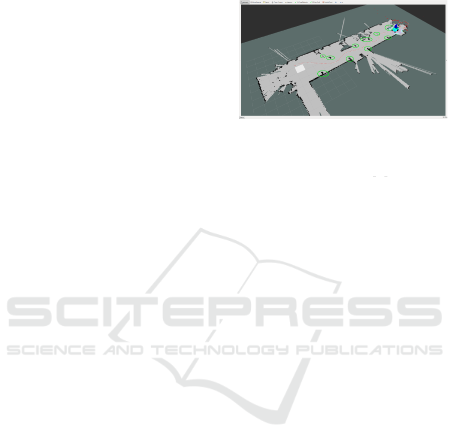
Figure 3: Schematics of the map.
in the fused grid maps. In each measurement the laser
scans a total of 512 readings distributed along 180
0
.
Meanwhile, the ROS depthimage to laserscan pack-
age is used to project RGB-D readings into 2D. Then,
each sensor reading is interpreted by the heuristic sen-
sor model. Afterwards, the recursive Bayes formula
is applied to fuse and update the data in each proba-
bilistic grid map, e.g. the RGB-D and laser maps.
To visualize the map making process and the nav-
igation, Figure 3 shows the RVIZ which is a ROS vi-
sualization tool. In the right part, the PWC-URDF
(unified robot description format) model can be seen,
the local map is represented as inflated sky-blue ob-
stacles that surround the URDF. The obstacles in the
global map are represented as black and the location
of the main obstacles are surrounded by a green el-
lipse, while the light and dark grays represents the
empty and unknown areas respectively, the fused sen-
sor readings that are used for localization, navigation
and to feed the local map can be spotted as red con-
tour that are situated in front of the PWC. And, the
path travel can also be seen on the empty area of the
map.
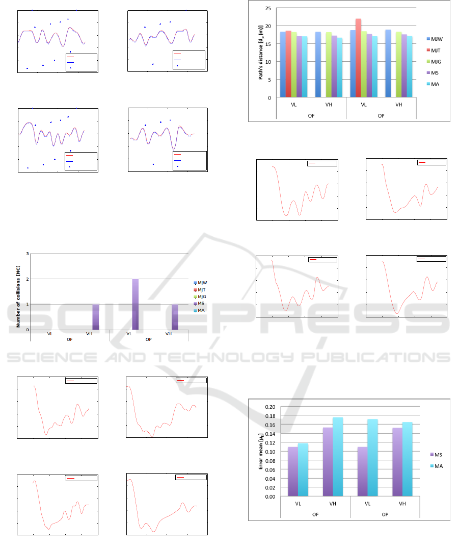
6 MAIN FINDINGS AND
RESULTS
Figures 4, 6 and 8 show the bar plots of the pilot tests
dependent variables T
P
, V
A
, N
C
and d
P
outcomes for
the factors ([M], [V ], [O]) and their corresponding lev-
els (M
A
, M
S
, M
JG
, M
JW
, M
JT
), (V
L
, V
H
) and (O
F
, O
P
).
It can be observed in Figure 4 that (O
P
, V
H
, M
A
)
and (O
P
, V
L
, M
A
) takes almost the same time to
travel the path even though the velocities are differ-
ent. Whereas, (O
F
, V
H
, M
A
) and (O
F
, V
L
, M
A
) takes
different time due to the reduction of obstacles. Then,
when driving the PWC in M
S
, (O
F
, V
L
) takes less
time than (O
P
, V
L
), in the same way (O
P
, V
L
) takes
more time than (O
P
, V
H
). It can also be observed
that (O
p
, M
JT
) is the longest path’s time of all modes.
Towards a User-wheelchair Shared Control Paradigm for Individuals with Severe Motor Impairments
249
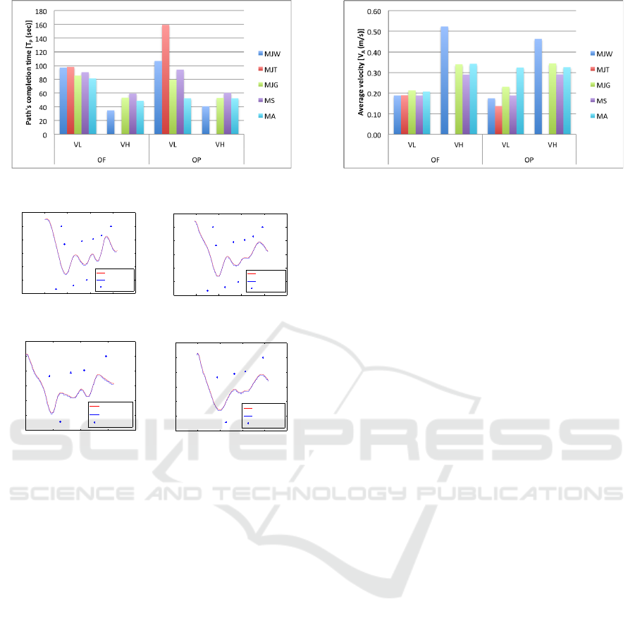
Figure 4: Time of the path.
−5 0 5 10 15 20
−1.5
−1
−0.5
0
0.5
1
1.5
Path in X [m]
Path in Y [m]
Path of the robot
localization
planning
obstacles
(a)
0 5 10 15 20
−1.5
−1
−0.5
0
0.5
1
1.5
Path in X [m]
Path in Y [m]
Path of the robot
localization
planning
obstacles
(c)
−5 0 5 10 15 20
−1.5
−1
−0.5
0
0.5
1
1.5
Path in X [m]
Path in Y [m]
Path of the robot
localization
planning
obstacles
(b)
−5 0 5 10 15 20
−1.5
−1
−0.5
0
0.5
1
1.5
Path in X [m]
Path in Y [m]
Path of the robot
localization
planning
obstacles
(d)
Figure 5: Autonomous mode (M
A
); a) fast velocity with
many obstacles. b) slow velocity with many obstacles c)
slow velocity with few obstacles. d) fast velocity with few
obstacles.
This fact could be because the user was inexperienced
with the ITCS. And, it is believed that this situation
can be improved by practicing using the tongue to
control the wheelchair. In the other hand (O
p
, M
JT
)
takes less time, this is due to the fact that there is
less obstacles and the user is able to control better the
ITCS. However, the shortest path’s time of all modes
is (O
F
, V
H
, M
JW
). It is important to mention that
user was proficient and has experience in controlling
hand-operated joysticks like the (M
JW
).
Figure 5 shows the M
A
plots of the path traveled
by the PWC for the different velocities and and also
shows the location of the obstacles. The blue path cor-
respond to the global planner whereas the red paths
correspond to the position of the PWC based on the
localization algorithm. The planner is computing new
paths constantly from its current position to the goal
while the PWC is traveling, producing a different final
path when compared with the initial one. In this con-
text the PWC is able to follows constantly and quite
accurately the re-planned paths, hence the final path.
Figure 6: Average velocity.
Figure 6 depicts the results of the V
A
pilot test.
It can be seen that the average velocity between
(O
P
, V
L
, M
A
) and (O
P
, V
H
, M
A
) is almost the same
even though the PWC was run in two different veloc-
ities. The reason for this could be that while driving
in (V
H
, M
A
), there is a delay for the PWC to react to
follow the initial path allowing the global planner to
constantly computing paths a bit longer than it should
be. The situation changes in M
A
when there is O
F
,
this means that the planner computes a path with less
pronounced curves, making the PWC to follow closer
the constantly computed paths. In the other hand,
(O
P
, V
L
, M
S
) takes slower velocity when compared
with (O
P
, V
H
, M
S
). The fact for this could be that the
initial point was in the right side bottom of the map,
allowing the planner to plan a more straight path, so
the PWC did not face sharp curves as in the later case.
Moreover, (O
p
, M
JT
) and (O
F
, V
H
, M
JW
) show the
slowest and fastest traveled paths of all modes respec-
tively.
Figure 7 shows the plots of the path travel by the
PWC in its independent variables, as in the M
S
mode
the path traveled by the PWC follow quite accurately
the path planned by the global planner.
The collision outcome corresponding to the de-
pendent variable N
C
is depicted in Figure 8. It can
be noticed that the PWC touches obstacles just in M
S
,
one in (O
p
, V
H
), two in (O
p
, V
L
) and one (O
F
, V
H
)
respectively.
Figure 9 shows the path for the USB gamepad joy-
stick mode M
JG
for different velocities (V
H
, V
L
) and
for different obstacles (O
P
O
F
).
Figure 10 depicts the path travel distance d
P
outcome, it clearly shows the longest distance
is (O
P
, V
L
, M
JT
) as well as the shortest one
(O
F
, V
H
, M
A
).
Figure 11 shows the path for the PWC joystick
mode M
JW
for different velocities (V
H
, V
L
) and for
different obstacles (O
P
O
F
).
Figure 12 and 13 show the the mean and vari-
ance of the planned paths and the executed ones in
M
A
and M
S
respectively. Whereas Figure 14 depicts
ICINCO 2016 - 13th International Conference on Informatics in Control, Automation and Robotics
250
0 5 10 15 20
−1.5
−1
−0.5
0
0.5
1
Path in X [m]
Path in Y [m]
Path of the robot
localization
planning
obstacles
(a)
0 5 10 15 20
−1.5
−1
−0.5
0
0.5
1
Path in X [m]
Path in Y [m]
Path of the robot
localization
planning
obstacles
(c)
0 5 10 15 20
−1.5
−1
−0.5
0
0.5
1
Path in X [m]
Path in Y [m]
Path of the robot
localization
planning
obstacles
(b)
0 5 10 15 20
−1.5
−1
−0.5
0
0.5
1
Path in X [m]
Path in Y [m]
Path of the robot
localization
planning
obstacles
(d)
Figure 7: Semi-autonomous mode (M
S
); a) fast velocity
with many obstacles. b) slow velocity with many obstacles
c) slow velocity with few obstacles. d) fast velocity with
few obstacles.
Figure 8: Collisions.
−5 0 5 10 15 20
−1
−0.5
0
0.5
1
1.5
Path in X [m]
Path in Y [m]
Path of the robot
USB Joystick
(a)
−5 0 5 10 15 20
−1
−0.5
0
0.5
1
1.5
Path in X [m]
Path in Y [m]
Path of the robot
USB Joystick
(c)
0 5 10 15 20
−1
−0.5
0
0.5
1
1.5
Path in X [m]
Path in Y [m]
Path of the robot
USB Joystick
(b)
0 5 10 15 20
−1
−0.5
0
0.5
1
1.5
Path in X [m]
Path in Y [m]
Path of the robot
USB Joystick
(d)
Figure 9: USB gamepad joystick mode (M
JG
); a) fast ve-
locity with many obstacles. b) slow velocity with many ob-
stacles c) slow velocity with few obstacles. d) fast velocity
with few obstacles.
the tongue joystick mode (M
JT
) with many and few
obstacles.
Figure 10: Distance of the path.
−5 0 5 10 15 20
−1
−0.5
0
0.5
1
1.5
Path in X [m]
Path in Y [m]
Path of the robot
WC Joystick
(a)
−5 0 5 10 15 20
−1
−0.5
0
0.5
1
1.5
Path in X [m]
Path in Y [m]
Path of the robot
WC Joystick
(c)
−5 0 5 10 15 20
−1
−0.5
0
0.5
1
1.5
Path in X [m]
Path in Y [m]
Path of the robot
WC Joystick
(b)
−5 0 5 10 15 20
−1
−0.5
0
0.5
1
1.5
Path in X [m]
Path in Y [m]
Path of the robot
WC Joystick
(d)
Figure 11: PWC joystick mode (M
JW
); a) fast velocity with
many obstacles. b) slow velocity with many obstacles c)
slow velocity with few obstacles. d) fast velocity with few
obstacles.
Figure 12: Mean.
When comparing M
A
and M
S
in Figure 4 for dif-
ferent obstacles and time paths’ travel, one can ob-
serve that M
S
completes all the paths in a slightly
longer time span than M
A
. This fact can also be re-
flected in Figure 6 where V
A
in M
S
is slower than M
A
.
The reason for this situation is that in M
S
mode, a
global map with no obstacles has been used to find
a suitable goal in the desired direction which makes
Towards a User-wheelchair Shared Control Paradigm for Individuals with Severe Motor Impairments
251
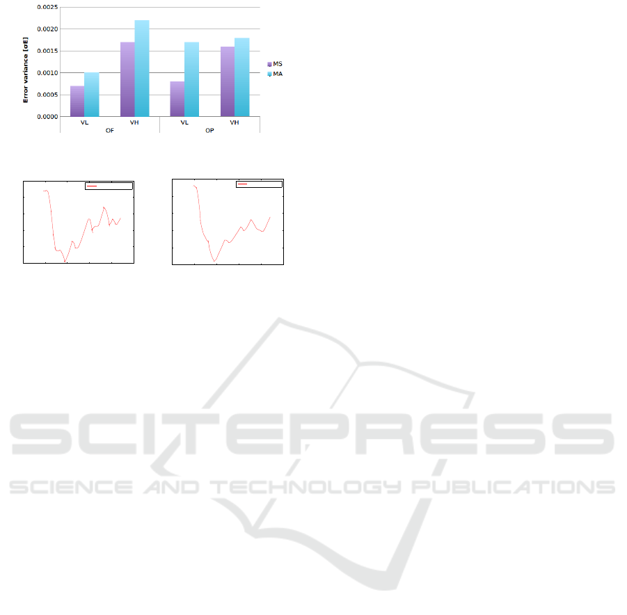
Figure 13: Variance.
−5 0 5 10 15 20
−1
−0.5
0
0.5
1
1.5
Path in X [m]
Path in Y [m]
Path of the robot
Tongue Joystick
(a)
−5 0 5 10 15 20
−1
−0.5
0
0.5
1
1.5
Path in X [m]
Path in Y [m]
Path of the robot
Tongue Joystick
(b)
Figure 14: Tongue joystick mode (M
JT
); a) many obstacles.
b) few obstacles.
the planned path not taking into account the obstacles.
Then, the NS relies only in the DWAP to avoid obsta-
cles towards the goal making the new re-calculated
paths with more pronounced curves and by conse-
quence longer paths. However, according to Figure
8, M
S
touches more obstacles than M
A
, this situation
could be because in M
S
the PWC seeks to go to the
end of the map avoiding obstacles on the way and
not taking into account the obstacles for the initial
path planning as it is done in M
A
. According to these
two modes, if one wants to go faster and care for not
touching obstacles, the M
A
is a good choice. When
taking an observation to M
J
in their three control in-
terfaces M
JG
, M
JW
and M
JT
, Figure 6 shows that the
fastest mode is M
JW
and this is due to the PWC runs
without any computer interface and uses all the mo-
tors’ power, in the other hand the other two modes
runs with a computer interface making them slower.
7 CONCLUSIONS
In this described preliminary study, two environment
setups were used for the pilot tests; a two room lab-
oratory and a corridor shape. The successful results
of the second pilot tests in their independent variables
have established the basis for:
• Preparing the framework for a full factorial de-
sign. For that, there is a necessity to overcome
the issues experienced in the experiments. A sim-
ilar problem experienced in both experiments is
that the planner plans the path too close to the ob-
stacles, especially when it goes through a narrow
doorway or turning around a wall corner. In the
case of the first experiment the wheelchair could
not go through a doorway because a ROS secu-
rity plugin canceled the navigation. The solution
to this problem is to develop two ROS plugins; the
first one for global voronoi path planning (Garrido
et al., 2006), and the second for escape-security
conditions. In the second experiment the PWC
touched some obstacles, especially in M
S
. The so-
lution to this is to improve the shared-control al-
gorithm, e.g. by taking into account the map with
obstacles when calculating the path to the desired
direction.
• Testing the system with higher speed. We have
tried to push the navigation to its limits and over
its limits with the actual high velocity with no suc-
cess. However, we believe that the main reason is
that the performance of the system was not opti-
mal. Therefore, an optimal relation between path-
following and high-speed must be found in order
to test the system at higher speed.
• Testing the system in all the independent variables
under challenged conditions, e.g. paths where the
PWC must go through narrow doorways from one
room to another, in cluttered spaces and, also with
dynamic obstacles.
• Making a proper ANOVA analysis using at least 5
participants per control-mode and several repeti-
tions per experimental condition. Randomization
will be necessary.
The actual shared-control strategies have mainly fo-
cused on sharing the control of the PWC to the user in
collision situations. On the other hand, this study has
shown a preliminary optimal distribution of tasks and
has provided the basis for further research on optimal
distribution of high-level control tasks between the
autonomous and the user-controlled modes for dif-
ferent situations depending on the control interface
and the users’ abilities. We believe that this research
will lead to the development of a novel shared-control
paradigm for individuals with severe motor impair-
ments. The capabilities of the shared control algo-
rithms need to be tested in indoor environments. The
abilities and needs of users with high level spinal cord
injury are different from those of spastic users, or
users with ALS (Simpson et al., 2008). Therefore, the
amount of user-control and the amount of automation
required is different for each user and each situation.
This not only depends on the amount and quality of
input the user can give to the system, but also on the
context and the environment that the system is operat-
ing in. Therefore, we also believe that when this new
ICINCO 2016 - 13th International Conference on Informatics in Control, Automation and Robotics
252

paradigm is fully implemented it will help wheelchair
users with severe motor impairments to interact more
efficiently with the environment.
ACKNOWLEDGMENT
This work was supported by The Ministry of Educa-
tion, Youth and Sports from the National Programme
of Sustainability (NPU II) project ”IT4Innovations
excellence in science - LQ1602 and by the project
IGA FIT-S-14-2486. It was also performed in col-
laboration between Brno University of Technology,
Czech Republic and H
´
ector Caltenco who is with the
Department of Design Sciences, Certec, Lund Uni-
versity, Sweden.
REFERENCES
Andreasen, S. L. N. S. (2006). An inductive tongue com-
puter interface for control of computers and assistive
devices. IEEE Transactions on biomedical Engineer-
ing, 53(12):2594–2597.
Caltenco, H. A., Lontis, E. R., and Andreasen, S. L. (2011).
Fuzzy Inference System for Analog Joystick Emula-
tion with an Inductive Tongue-Computer Interface. In
15th Nordic-Baltic Conference on Biomedical Engi-
neering and Medical Physics (NBC 2011), volume 34,
pages 191–194. IEEE, Springer Berlin Heidelberg.
Ch
´
avez, P. A. and Karstoft, H. (2014). Map building based
on a xtion pro live rgbd and a laser sensors. Journal
of Information Technology & Software Engineering.
Christensen, H. V. and Garcia, J. C. (2003). Infrared
Non-Contact Head Sensor, for Control of Wheelchair
Movements. Assistive Technology: From Virtuality
to Reality, A. Pruski and H. Knops (Eds) IOS Press,
pages 336–340.
Cooper, R., Boninger, M., Kwarciak, A., and Ammer,
B. (2002). Development of power wheelchair chin-
operated force-sensing joystick. In [Engineering in
Medicine and Biology, 2002. 24th Annual Conference
and the Annual Fall Meeting of the Biomedical En-
gineering Society] EMBS/BMES Conference, 2002.
Proceedings of the Second Joint, volume 3, pages
2373–2374. IEEE.
Elfes, A. (1989a). A tessellated probabilistic representation
for spatial robot perception and navigation. Proceed-
ings NASA Publications, 3(N90).
Elfes, A. (1989b). Using occupancy grids for mobile robot
perception and navigation. Computer, 22(6):46–57.
Faria, B. M., Reis, L. P., and Lau, N. (2013). Manual, au-
tomatic and shared methods for controlling an intelli-
gent wheelchair: Adaptation to cerebral palsy users.
In: 13th International Conference on Autonomous
Robot Systems and Competitions, pages 26–31.
Garrido, S., Moreno, L., Abderrahim, M., and Monar, F. M.
(2006). Path planning for mobile robot navigation
using voronoi diagram and fast marching. In IROS,
pages 2376–2381. iSBN: 1-4244-0259-X.
Jeonghee, K., Xueliang, H., and Maysam, G. (2008). Wire-
less control of powered wheelchairs with tongue mo-
tion using tongue drive assistive technology. An-
nual International Conference of the IEEE Engineer-
ing in Medicine and Biology Society. IEEE Engi-
neering in Medicine and Biology Society. Conference,
2008:4199–4202.
Jeonghee, K., Xueliang, H., Minocha, J., Holbrook, J.,
Laumann, A., and Maysam, G. (2012). Evalua-
tion of a smartphone platform as a wireless interface
between tongue drive system and electric-powered
wheelchairs. IEEE Trans. Biomed. Engineering,
59(6):1787–1796.
Jiding, D., Zhijun, L., Chenguang, Y., and Peng, X.
(2014). Shared control of a brain-actuated intelligent
wheelchair. pages 341–346. IEEE.
Lund, M. E., Christiensen, H. V., Caltenco, H. A., Lontis,
E. R., Bentsen, B., and Andreasen, S. L. N. (2010).
Inductive tongue control of powered wheelchairs. In
Proceedings of the 32nd Annual International Confer-
ence of the IEEE Engineering in Medicine and Biol-
ogy Society, pages 3361–3364. Isbn = 978-1-4244-
4123-5.
Moravec, H. and Elfes, A. (1985). High resolution maps
from wide angle sonar. In Robotics and Automation.
Proceedings. 1985 IEEE International Conference on,
volume 2, pages 116–121. IEEE.
Petry, M., Paulo, A. M., Braga, R., and Paulo, L. R. (2010).
Shared control for obstacle avoidance in intelligent
wheelchairs. in IEEE Conference on Robotics, Au-
tomation and Mechatronics, pages 182–187.
Quigley, M., Conley, K., Gerkey, B., Faust, J., Foote, T. B.,
Leibs, J., Wheeler, R., and Ng, A. Y. (2009). ROS: an
open-source robot operating system. In ICRA Work-
shop on Open Source Software.
San Agustin, J., Mateo, J., Paulin, H. J., and Villanueva,
A. (2009). Evaluation of the potential of gaze input
for game interaction. PsychNology Journal, 7(2):213–
236.
Simpson, R. C., LoPresti, E. F., and Cooper, R. A.
(2008). How many people would benefit from a smart
wheelchair? Journal of Rehabilitation Research and
Development, 45(1):53–72.
St
ˇ
ep
´
an, P., Kulic, M., and P
ˇ
reu
ˇ
cil, L. (2005). Robust data
fusion with occupancy grids. In IEEE Transactions
on Systems, Man, and Cybernetics, pages 106–115.
IEEE.
Torsten, Felzer and Rainer, Nordman (2007). Alternative
wheelchair control. In Proc. Int. IEEE-BAIS Symp.,
Res. Assistive Technol., pages 67–74.
Xueliang, H. and Maysam, G. (2010). Evaluation of a wire-
less wearable tongue-computer interface by individ-
uals with high-level spinal cord injuries. Journal of
Neural Engineering, 7(2). ISBN: 17412560.
Towards a User-wheelchair Shared Control Paradigm for Individuals with Severe Motor Impairments
253
