
An Advanced, Adaptive and Multimodal Graphical User Interface for
Human-robot Teleoperation in Radioactive Scenarios
Giacomo Lunghi
1,2
, Raul Marin Prades
2
and Mario Di Castro
1
1
Engineering, CERN, 23, CERN, 1211, Geneva, Switzerland
2
Universitat Jaume I, Castelln de la Plana, Spain
Keywords:
Human-robot Interaction, Telerobotics and Teleoperation, Graphical User Interface, Network Robots,
Engineering Applications.
Abstract:
In this paper we present the user interface of a tele-robotic system, which allows CERN users to perform visual
inspections and tele-manipulation tasks inside the CERN accelerator complex. This graphical user interface
has been designed to be simple to use, in order to provide the operator with a comfortable system. Moreover,
the user interface is robot independent and it adapts itself to the robot configuration, in order to provide a
general way for controlling any kind of robot used at CERN. Furthermore it allows the operator to choose
between different kinds of input (e.g. keyboard, joypad, haptic device, etc), in order to provide the most easy
human-robot interaction interface, which is a fundamental requirement for safe operations.
1 INTRODUCTION
The need of robotic platforms that can be tele-
operated safely is becoming predominant: the use of
robots in many industrial facilities can reduce the hu-
man risks to hazards (e.g. radioactivity, chemical and
electrical risks, oxygen deficiency etc.) and can also
increase the running time of the industrial plant, with-
out the need of stopping the entire system in case of
problems for allowing human operations (Keller et al.,
2008). However, industries are still not confident in
the usage of such a kind of robot for emergency main-
tenance and for non-automatic tasks, since the equip-
ment is usually delicate and expensive, and the inter-
action of the robot with it could create bigger dam-
ages, with the need of a longer human intervention.
CERN, the Organisation europenne pour la
recherche nuclaire, counts more than 50 km of un-
derground facilities which contains high technology
equipment that requires constant inspection and main-
tenance. The need of robotic tele-operated platforms
for CERN is increasing every year, due to the im-
provement of the machines, which will bring, among
other things, an increasing of the radiation, which will
make human interventions more difficult (Kershaw
et al., 2013). Nowadays the commercial robotic plat-
forms which can allow this kind of interventions are
usually robots designed for military purposes, which
provide the necessary safety, bringing, though, a se-
ries of technology limitations which confines their us-
age.
One of the main limitations of such robots is the
usability of the system: robots operators usually re-
quire constant training limiting the number of opera-
tion personnel that can use the robot. The company,
then, has to create a team of robot operators that will
perform all the necessary interventions. Nevertheless,
an industrial facility presents often a huge number of
different components which could require a robotic
manipulation: the robot operator, then, is well trained
in the robot usage, but can’t have the complete knowl-
edge and the experience about the area in which the
intervention will take place and the characteristics of
the component to manipulate. It would be better, then,
to provide an easy to learn and easy to use robotic
system to the component responsible, who has the re-
quired knowledge about the component and the sur-
ronding environment to perform the operation in a
safer way.
Remote manipulation in industrial plants is still
an open issue and it has been treated for more than
20 years (Rolfe et al., 1999)(Rolfe, 2007)(Desbats
et al., 2008): a lot of effort, for example, has been put
in teleoperation control using haptic devices which
are able to provide direct feedbacks to the operator
(C¸ avus¸o
˘
glu et al., 2002).
A Human Robot Interface is the bridge between
the operator and the workspace, it is composed by in-
put devices and output devices, it must be easy to use,
robust, complete and it must make as easy as possible
224
Lunghi, G., Prades, R. and Castro, M.
An Advanced, Adaptive and Multimodal Graphical User Interface for Human-robot Teleoperation in Radioactive Scenarios.
DOI: 10.5220/0005971402240231
In Proceedings of the 13th International Conference on Informatics in Control, Automation and Robotics (ICINCO 2016) - Volume 2, pages 224-231
ISBN: 978-989-758-198-4
Copyright
c
2016 by SCITEPRESS – Science and Technology Publications, Lda. All rights reserved

the accomplishment of the task by the operator.
According to (Ferre, 1997) the main requirements
of a Human Robot Interface are:
• to establish all the necessary connections between
the operator and the remote workspace. There are
two kind of connections: the actuation of the op-
erator on the remote workspace and, in the oppo-
site direction, the feedback of information to the
operator;
• to make easier the execution of task allowing the
operator to send high level commands as well as
make possible the direct actuation whenever nec-
essary;
• to give operator all the necessary information of
the workspace with the goal of reaching the high-
est level of transparency. This will allow the op-
erator to accomplish the task with dexterity as
well as making easier the supervision of the semi-
automatic tasks.
Studies on design of usable and learnable Graphical
User Interfaces have already been done, like in (Mar
´
ın
et al., 2005). Nevertheless, these GUIs are optimized
to work on a specific robot in a confined and well-
known area and they do not adapt to different robotic
platforms or arms, which are dislocated in harsh and
unknown environments.
The goal of this paper is to present the results of a
preliminary multimodal (Cohen et al., 1998) Graphic
User Interface, that is both learnable and usable, and
to highlight the requirements for the future develop-
ment of a complete robotic system that can be given to
unexpert and untrained operators in order to perform
manipulation in the CERN facilities. In the next sec-
tion the GUI is presented highlighting the graphical
structure and the available input devices. Then, the
GUI is validated through a series of tests performed
by different kind of operators and the results are re-
ported in number of failures, average time of com-
pletion and number of collisions. Finally, a series of
future improvements is listed.
2 SYSTEM OVERVIEW
2.1 Communication
The graphical user interface communicates with the
robot through the CERN network, which allows to
establish a connection with any device connected
through ethernet, WiFi and GSM/UMTS inside the
CERN area. Especially, CERN provides an internal
full 4G coverage, which must be always available for
safety reasons, in order to provide a worker with the
possibility to call using his/her mobile phone in case
of emergency. In this way, all the devices connected
to the CERN network are reachable from any other
device.
Taking advantage of this network infrastructure,
it is possible to control any active robot on the CERN
area using a standard PC. The robot, then, can be con-
nected to the network using WiFi, if available, or 4G.
The Graphical User Interface contains the list of
all the controllable robots, together with the robot
configuration (e.g. manipulator structure, number of
cameras, position of cameras, robot 3D model, plat-
form type and dimensions etc.). In the connection
phase then, the GUI shows to the operator the list
of available robots and their position. When clicking
on a robot, the hardware configuration of the robot is
shown, providing information about the connectivity
and availability of the robot.
When the operator presses Connect the GUI es-
tablishes the communication with the robot, adapting
itself to the stored robot configuration. At the connec-
tion, different network sockets are opened:
• a TCP Service socket on which service messages
are sent;
• a TCP Control socket for each controllable device
(i.e. platform, arm and PTZ camera);
• a RTP Camera socket for each camera feed.
Apart from the Service socket all the unused sockets
are paused by the GUI in order to not occupy band-
width (e.g. a not used camera, or the platform Control
socket while using the arm).
2.1.1 Clock Synchronization
Using an Internet-based network can create problems
in terms of communication delays. Having precise
timestamps is, then, a fundamental requirement, in
order to measure the delay of the controls and of
the video feedback. In this paper there is any treat
of these delays, but it provides a system to measure
them, which can be used for future work.
For this reason the GUI already includes the
timestamp of the messages in the communication
protocol. In order to provide precise timestamps,
the Graphical User Interface and the robot have to
synchronize their internal time at the beginning of
the communication. The synchronization model is
based on the usual four timestamp mechanism of the
Network Time Protocol (NTP). This commonly-used
mechanism measures the transmission delay between
communicating nodes and uses this to estimate the
An Advanced, Adaptive and Multimodal Graphical User Interface for Human-robot Teleoperation in Radioactive Scenarios
225
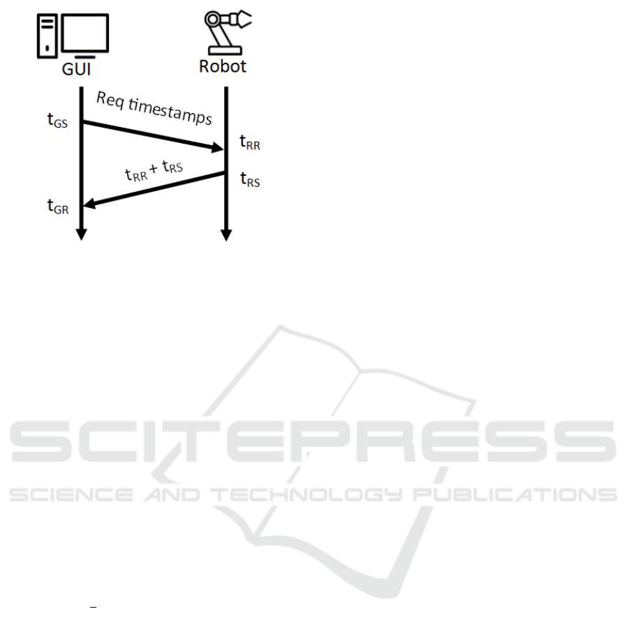
Figure 1: Synchronization model between the Graphical
User Interface and the robot.
offset between their respective clocks, in order to de-
termine the error in the client nodes clock with respect
to the time servers clock.
At the connection the GUI sends on the TCP Ser-
vice socket a request for a timestamp to the robot at
the GUI time t
GS
. The robot receives the message at
the robot time t
RR
and sends at the robot time t
RS
,
both the timestamps t
RR
and t
RS
. The GUI receives
the message from the robot containing the two times-
tamps at the GUI time t
GR
.
The GUI then uses the four timestamps to cal-
culate the clock offset and roundtrip message delay
relative to the server. The GUI can then reset its
own clock to compensate for any difference with the
servers clock. The timestamping mechanism is de-
signed based on an assumption that the forward and
backward communication delays are symmetric.
The delay in the communication t
d
then is equal
to:
t
d
=
1
2
[(t
GS
+t
GR
) − (t
RS
+t
RR
)] (1)
The synchronization model is highlighted in Figure
1. More precise timestamps can be obtained using
techniques like the one proposed in (Tian et al., 2008).
2.2 Control Interface
As soon as the operator connects to a robot, the
Graphical User Interface adapts itself to the robot con-
figuration and the available input devices. It uses also
previously saved personalized configurations of the
user, if stored.
The control window of the GUI is organized as
shown in Figure 2. On the left side the list of cam-
eras mounted on the robot is available. The operator
can choose a main camera, that will be shown bigger
in the center of the window, and a secondary camera,
which will be shown smaller in one of the corners of
the bigger camera. In this way, the operator can see
simultaneously two cameras at the same time. In case
of multiple screens, the secondary camera can be de-
tached from the main window and opened in a sepa-
rated one, in order to have it bigger and more visible.
On the left bottom side there is the output console,
where all the messages from the robot and the GUI
(e.g. warnings and errors) are printed.
On the right top side there are the control modes.
The GUI provides the following control modes, de-
pending on the selected robot component; for a
robotic platform the GUI allows two drive modes:
• slow, in which the control maximum speed is the
50% of the platform maximum speed;
• fast, in which the control maximum speed is the
100% of the platform maximum speed.
Three control modes are allowed for a robotic arm:
• joint-by-joint control, in which the operator can
control every joint of the robotic arm;
• cartesian control, in which the operator can con-
trol the robotic arm, with the possibility of choos-
ing as reference coordinate system, the base of the
arm or the tool centre point;
• gripper, in which the operator can control the
gripper.
For a pan-tilt-zoom camera only one control mode
is allowed, which allows to move the camera and to
zoom in and out.
On the right bottom side it is possible to choose
the input device. The available input devices are listed
in a combo-box, and selecting a different input de-
vices changes the control view in the centre bottom
side. For safety reasons, changing the input device
stops all the control modes, in order to avoid unex-
pected behaviours.
The central bottom side contains the input view.
This part adapts to the robot configuration and to the
input device. Further information can be retrieved in
Section 2.3.
For all the input devices, a slider is always visible
in the bottom side of the interface: this slider sets the
gain for the sent control. The operator, then, can set
the operating speed of the robot at the selected per-
centage of the maximum speed.
2.3 Input Devices
The main goal of this graphical user interface is to
provide a comfortable and flexible system to the op-
erator for controlling the robot. Having the possibility
to choose between different input devices, then, it is a
ICINCO 2016 - 13th International Conference on Informatics in Control, Automation and Robotics
226
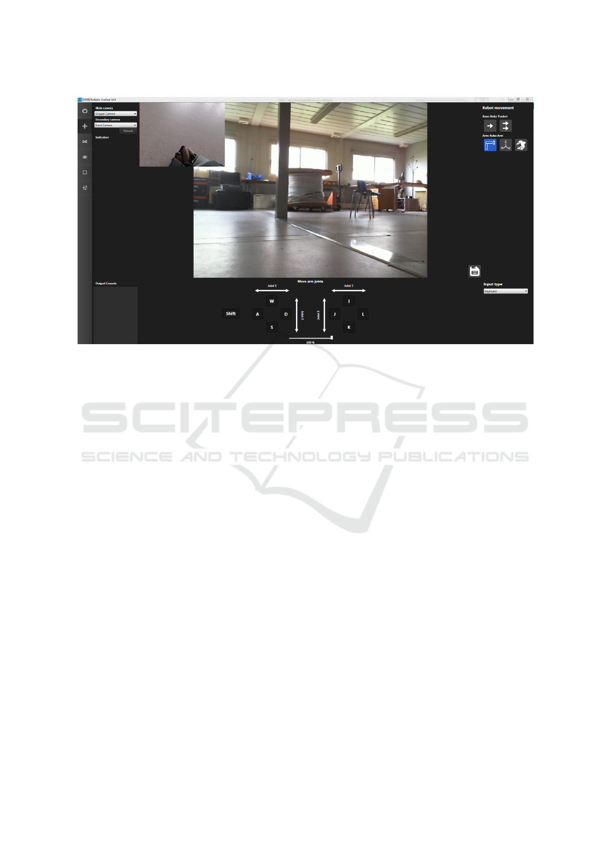
Figure 2: Control window of the Graphical User Interface connected to a robotic platform equipped with a robotic arm and
two cameras, with the keyboard as a selected input device.
fundamental requirement for achieving this flexibility.
All the input devices are able to control all the types
of robot, adapting every time the control system to the
robot configuration. The currently implemented input
controllers are the following:
• keyboard
• XInput joypad
• RGB-D sensor
• haptic device
• shell programming
The robot control using the keyboard or an XInput
joypad is quite similar: using the keyboard the keys
combination WASD for the left hand the IJKL for the
right hand are used; using an XInput joypad the oper-
ator uses the two analog sticks.
While driving the platform the left hand can con-
trol the longitudinal speed and the lateral speed (if
present, when using omni-directional wheels); the
right hand controls the rotation of the platform. When
controlling a robotic arm, instead, using the joint
by joint mode, the operator can control two joints
per hand. The control of the joints depends on the
arm configuration (number of joints, direction of the
joints) in order to provide a control as much similar
as possible to the real configuration of the arm. Since
with two hands it is possible to control only 4 joints,
the operator can keep pressed the left shift key or a
button on the controller to control the remaining joints
of the arm.
The control of a robotic arm in Cartesian control
mode using the keyboard or the joypad, instead, is
more sophisticated: if the coordinate reference sys-
tem is the arm base, then, the left hand controls the X-
Y coordinate of the end-effector while the right hand
controls its pitch and roll; pressing the left shift but-
ton of the keyboard or a button on the joypad, the left
hand controls the X-Z coordinate of the end-effector
while the right hand controls its pitch and yaw. This
behaviour of the left hand is different when control-
ling a robotic arm with the reference coordinate sys-
tem in the tool centre point: the left hand, in fact,
controls the X-Z of the end effector and X-Y while
pressing the left shift button of the keyboard or a but-
ton on the joypad. This setting gives to the operator
the feeling of navigating in the environment with the
arm when using the reference coordinate system in
the tool centre point.
The operator control using the RGB-D sensor uses
the tracking of the hands of the operator for moving
the robots: while moving a robotic platform, the oper-
ator uses the hands like while using a steering wheel
(Figure 2). Moving the hands forward will acceler-
ate the platform, while pulling them back will slow it
down. Turning left and right will turn the platform:
the rotation rate of the platform is function of the dif-
ference in the vertical position of the two hands. For
stopping the robot it is sufficient to clap the hands,
or removing the hands from the field of view of the
sensor.
An Advanced, Adaptive and Multimodal Graphical User Interface for Human-robot Teleoperation in Radioactive Scenarios
227

A RGB-D sensor can be used also for controlling
a robotic arm: in this case only the world coordinate
control is allowed. The operator uses his right hand to
control the arm: all the control is done converting rel-
ative movements of the hand in the robot workspace.
For safety, the operator can move the robot only if the
hand is open; closing the hand will stop immediately
the robot.
Figure 3: Synchronization model between the Graphical
User Interface and the robot.
The robotic arm control is possible also using a
haptic device: two solutions have been implemented
but only one has been decided to be deployed on the
GUI. The first one maps the workspace of the hap-
tic device in the workspace of the arm: this solution
is not optimal in term of usability since it doesnt al-
low very precise movements. Furthermore, most of
the intervention shown that the manipulation is done
only on one side of the robot (the front or one of the
sides): mapping the entire workspace of the arm on
the workspace of the haptic device then is not opti-
mal, in case of working on the side of the robot, since
the operator has to work in a uncomfortable position
with the device.
The second solution, instead, maps movement
variations of the haptic device in arm movement: in
this way the operator can change the relationship be-
tween robot movements and haptic device movements
and, if working in a confined robot space, can use
the entire workspace of the device with higher pre-
cision. This solution carries the problem that the
robot workspace can be bigger than the haptic device
workspace: in the case that the operator arrives to the
end of the workspace of the haptic device while he
needs to continue in the same direction with the robot,
he has to stop the command sending from the haptic
device to the robot, to move in a better position the
device, and to start sending commands again. The
suggested approach in this case is to approach the in-
tervention workspace using another input device and
then using the haptic device for very precise move-
ments.
The last input option is the online programming
of the movements: the operator can create scripts in
order to perform repetitive operations in an automatic
way. The operator can use a simple script language
to move the robot (e.g. MOVE BASE 10 cm FOR-
WARD, TURN BASE 45 deg LEFT, ARM IN SAFE
POSITION), that can be combined together and cre-
ate a sequence program for the robot. The script can
be saved and loaded at any time. The operator can
pause the program at any moment or stop it and can-
cel it. This script language can be very useful in case
of presence of tools on the robot in a precise position
(programs which get and leave the tools on the base),
and to perform delicate operation automatically (un-
screwing a screw once the arm has been well aligned
to the screw). The GUI provides a visual IDE to cre-
ate, save and load programs.
2.4 Robot 3D Model
While performing manipulation tasks, it is often diffi-
cult to understand the pose of the arm using only the
on-board cameras. This problem is enhanced when
the operator controls the robot in world coordinate
since, sometimes, the inverse kinematics of the robot
chooses unpredictable poses: nevertheless, the oper-
ator sees the arm moving as expected, forgetting to
constantly check the arm pose, increasing the risks of
collisions. In order to provide as more information as
possible about the robot to the operator, a 3D model
of the robot can be opened while controlling it. The
3D model shows only the robot pose in real-time and
can be opened in a separate window and kept next to
the control window.
In this section the Graphical user interface is pre-
sented. In the next section the technologies used for
implementing it are shown.
3 SYSTEM IMPLEMENTATION
The Graphical User Interface is designed to work on
Microsoft Windows since it is the most used operating
system at CERN. It is implemented using C# using
WPF for the design of the graphic part. Nevertheless,
a version of the GUI implemented in Java has been
develop in order to provide a more portable version of
the system. The Java version of the GUI provides all
the functions except the support to the RGB-D sensor
and the 3D model of the arm.
The 3D model is implemented in Autodesk Inven-
tor and the communication between the GUI and in-
ventor is done using the provided SDK.
4 SYSTEM VALIDATION
The goal of the system validation of this GUI is to
prove its learnability, in terms of ability of the user
of learning the functionality of the system, and the
ICINCO 2016 - 13th International Conference on Informatics in Control, Automation and Robotics
228
usability. For this purpose a series of tests have been
designed using both a platform and a robotic arm. In
this section, first, the tests are described; then the tests
rules are defined. Three categories of operators have
been chosen for the validation. Finally, the results of
the tests are shown.
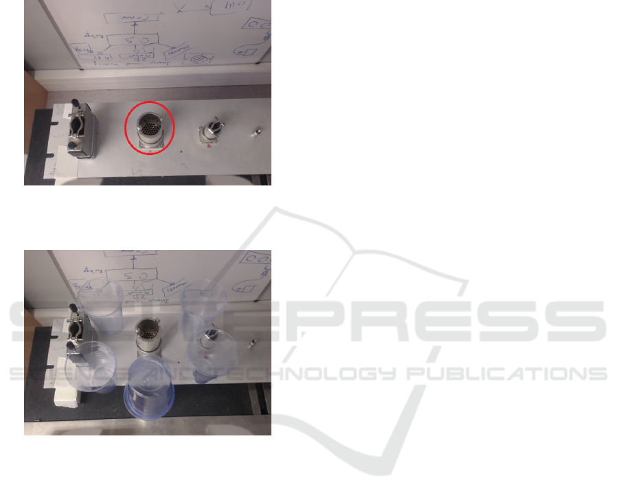
Figure 4: View from the gripper camera during the first at-
tempt of the first test. The operator had to unplug the circled
connector.
Figure 5: View from the gripper camera during the sec-
ond attempt of the first test. The operator had to unplug
the circled connector taking care of not touching the plas-
tic glasses surrounding it. This test was performed without
having a direct view of the robot.
4.1 Tests Description and Hardware
Configuration
Test 1: the operator has to use a Schunk Powerball
LWA 4P to detach a connector from a socket and to
leave the connector inside a container. The robot is
equipped with cameras, one on the gripper and one
on the robot base. Furthermore, two environmental
cameras have been installed, one looking at the side
of the robot and one looking at the front. Figure 4 and
figure 2 shows the test to be accomplished.
Test 2: the operator has to drive a Kuka Youbot
around a specified path. The path presents obsta-
cles, narrow corridors and sharp turns in a confined
space. The robot is equipped with three cameras, one
in front, one facing backward and one on the gripper
of the arm. It is also provided with a light, since part
of the test has been performed in a dark room.
4.2 Tests Rules
During these tests, any previous information about
them has been provided to the operators. Further-
more, the tests have been performed singularly, in or-
der not to provide any suggestion to the other oper-
ators. Both tests, in fact, allow different approaches,
especially regarding the usage of the cameras: seeing
another operator performing the same task, then, can
help a lot in the operating techniques.
Each operator has ten minutes to use freely the
GUI: in this time he or she can use both the plat-
form and the arm, with all the provided input devices
and all the settings. It has to be taken in to account
that this time is not enough for learning how to op-
erate a robot, since what count the most in this kind
of tasks is the experience: current robot operators at
CERN follow at least one week full time course in or-
der to get experience with the robot, discover the best
camera setting to perform a task and so on. Neverthe-
less, avoiding operators long training is the purpose of
this Graphical User Interface, together with usability.
Ten minutes, in the end, looked the perfect amount of
time for the operator to get enough confidence with
the control system, without getting experience.
Both tests have to be performed twice by each op-
erator: the first time the test can be performed look-
ing directly at the robot while the second time the op-
erator must use only the onboard cameras. Between
the two times, the test is slightly changed by moving
things in order to reduce the operator experience on
it.
4.3 Operators Selection
The following operators have been selected for the
tests:
• Two Expert Operators, who currently operate
the CERN commercial robots in facilities. As
previously said, these operators have already fol-
lowed more than one week specific training on
robot tele-operation and they have already per-
formed different interventions in underground fa-
cilities. Nevertheless, it has been their first ap-
proach to this robotic system.
• Two Project-involved Operators, who work in
similar robotic projects with the same hardware. It
has been possible, then, that they saw the system
during the development and they obtained some
An Advanced, Adaptive and Multimodal Graphical User Interface for Human-robot Teleoperation in Radioactive Scenarios
229
knowledge about the tests and the control system.
However, they did not have any experience in real
interventions.
• Two Entry-level Operators, who never saw both
the software and the hardware and they did not
have any experience in real interventions.
These three categories provide enough variety to vali-
date the learnability and the usability of the Graphical
User Interface.
4.4 Results
4.4.1 Test 1 Manipulation Task
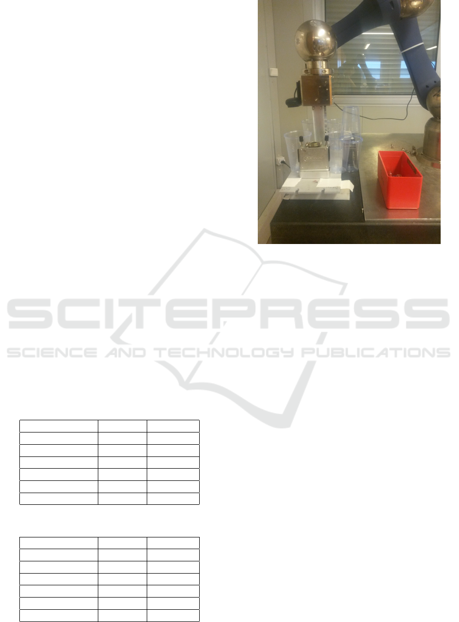
Initially, all the operators could try the robotic arm for
ten minutes with all the input devices, then they exe-
cuted the task of detaching a connector from a socket
and putting it inside a box. The test has been repeated
twice: the first time the operators could see the robot
and the operating area directly; the second time the
operators were operating the robot without directly
seeing it, but having only the onboard cameras as vi-
sual feedback. Nevertheless if the two attempts would
have been identical, the experience of the operators
about the experiment gained during the first attempt
would have influenced the results. For this reason
the second attempt has been made more difficult by
adding glasses around the connector: in this case the
operator had to be much more precise in order not to
touch the glasses.
In the following tables the results of the two at-
tempts are presented:
Table 1: First attempt.
Category # of fails Best time
Expert 0 40”
Expert 0 1’12”
Project involved 0 1’32”
Project involved 0 1’10”
Entry level 0 2’24”
Entry level 0 3’36”
Table 2: Second attempt.
Category # of fails Best time
Expert 0 56”
Expert 0 1’45”
Project involved 0 2’10”
Project involved 0 3’01”
Entry level 0 4’27”
Entry level 1 5’32”
Figure 6: The test robotic arm used during the second at-
tempt of the first test.
It can be noticed that the average completion time
is quite short. The second attempt has been consid-
ered by the operators considerably more complicated
than the first one. Most of the operators tried all the
input devices during the first attempt. During the sec-
ond attempt instead, the approach to the connector has
been done using different input devices (haptic de-
vice, RGB-D sensor), but for precise operation they
all used the keyboard for controlling the arm joint by
joint and the joypad for controlling the arm in world
coordinates. The common feedback during the oper-
ation with the haptic device and the RGB-D sensor is
the difficulties on moving the arm precisely and very
slowly.
4.4.2 Test 2 Driving Task
For the driving task only one attempt has been done:
the operators had the possibility to train with the base
for ten minutes has before and then they executed the
test directly without having the possibility to see the
robot. In this test the number of collisions with the
environment have been counted. In the next table the
results are presented:
All the operators considered this test very compli-
cated due to the difficulties to see the position of the
robot in the environment using only cameras. Only
the expert operators used the camera equipped on the
arm to check the space around the robot. In terms of
input device, they mainly used the RGB-D sensor and
ICINCO 2016 - 13th International Conference on Informatics in Control, Automation and Robotics
230
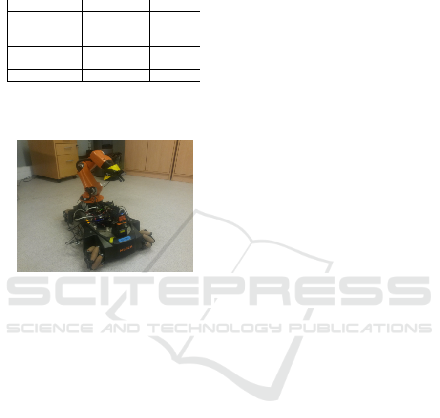
Table 3: Test 2 results.
Category # of collisions Best time
Expert 1 5’31”
Expert 0 4’20”
Project involved 3 6’51”
Project involved 6 5’45”
Entry level 3 8’46”
Entry level 8 10’29”
the joypad for the easiest part of the path, and they all
switched to the keyboard or the joypad for the most
difficult part.
Figure 7: The test platform used during the second test.
5 FUTURE WORK AND
CONCLUSIONS
In the future, more complex and precise feedbacks
have to be given to the operator. While operating a
robotic arm, it is extremely important to detect colli-
sions on the entire body of the arm: these feedbacks
can be reported visually to the operator, or physically,
actuating the haptic device or a sleeve equipped with
vibration buzzers can be worn by the operator.
Another important extension to the system is the
possibility to have a 3D view of the workspace: this
can be done using a depth camera mounted on the
robot. The collected information is then reported on
a 3D viewer. This will give to the operator the pos-
sibility to explore the workspace and to have multi-
ple views, which is not possible using only on board
cameras. Objects recognition and tracking could also
help the user in the grasping procedures and naviga-
tion (Mar
´
ın et al., 2002).
Above all, this paper showed that this preliminary
Graphical User Interface provides already an easy to
learn and easy to use environment. The feedbacks re-
ceived by the tester operators and their fast learning
time, as shown in the previous tables.
REFERENCES
C¸ avus¸o
˘
glu, M. C., Sherman, A., and Tendick, F. (2002).
Design of bilateral teleoperation controllers for hap-
tic exploration and telemanipulation of soft environ-
ments. Robotics and Automation, IEEE Transactions
on, 18(4):641–647.
Cohen, P. R., Johnston, M., McGee, D., Oviatt, S. L., Clow,
J., and Smith, I. A. (1998). The efficiency of multi-
modal interaction: a case study. In ICSLP.
Desbats, P., Garrec, P., Perrot, Y., Measson, Y., Geffard, F.,
David, O., Gargiulo, L., Idasiak, J.-M., and Piolain, G.
(2008). Overview of robotic technologies for nuclear
hazardous environments. In Proceedings of ANS Joint
topical meeting. Emergency Management & Robotics
for Hazardous Environments, March, pages 9–12.
Ferre, M. (1997). Interfaz Dise
˜
no de interfaces para robots
teleoperados. Desarrollo de un entorno de teleop-
eraci
´
on con caracter
´
ısticas multimedia. PhD thesis,
Tesis Doctoral. Universidad Polit
´
ecnica de Madrid.
1997. Madrid.
Keller, D., Perrot, Y., Gargiulo, L., Friconneau, J., Bruno,
V., Le, R., Soler, B., Tchah, M., Ponsort, D., Cham-
baud, P., et al. (2008). Demonstration of an iter rel-
evant remote handling equipment for tokamak close
inspection. In Intelligent Robots and Systems, 2008.
IROS 2008. IEEE/RSJ International Conference on,
pages 1495–1500. IEEE.
Kershaw, K., Feral, B., Grenard, J.-L., Feniet, T., De Man,
S., Hazelaar-Bal, C., Bertone, C., and Ingo, R. (2013).
Remote inspection, measurement and handling for
maintenance and operation at cern. International
Journal of Advanced Robotic Systems, 10.
Mar
´
ın, R., Sanchez, J., and Sanz, P. J. (2002). Object recog-
nition and incremental learning algorithms for a web-
based telerobotic system. In Robotics and Automa-
tion, 2002. Proceedings. ICRA’02. IEEE International
Conference on, volume 3, pages 2719–2724. IEEE.
Mar
´
ın, R., Sanz, P. J., Nebot, P., and Wirz, R. (2005). A
multimodal interface to control a robot arm via the
web: a case study on remote programming. Industrial
Electronics, IEEE Transactions on, 52(6):1506–1520.
Rolfe, A. (2007). A perspective on fusion relevant remote
handling techniques. Fusion Engineering and Design,
82(15):1917–1923.
Rolfe, A., Brown, P., Carter, P., Cusack, R., Gaberscik, A.,
Galbiati, L., Haist, B., Horn, R., Irving, M., Locke,
D., et al. (1999). A report on the first remote han-
dling operations at jet. Fusion engineering and design,
46(2):299–306.
Tian, G.-S., Tian, Y.-C., and Fidge, C. (2008). High-
precision relative clock synchronization using time
stamp counters. In Engineering of Complex Com-
puter Systems, 2008. ICECCS 2008. 13th IEEE Inter-
national Conference on, pages 69–78. IEEE.
An Advanced, Adaptive and Multimodal Graphical User Interface for Human-robot Teleoperation in Radioactive Scenarios
231
