
A Version-based Approach to Address Flexibility of BPMN
Collaborations and Choreographies
Imen BenSaid
1,2
, Mohamed Amine Chaabane
1
, Rafik Bouaziz
1
and Eric Andonoff
2
1
MIRACL, University of Sfax, Route de L’Aéroport, BP 1088, 3018 Sfax, Tunisia
2
IRIT, University of Toulouse 1, 2 Rue du Doyen Gabriel Marty, 31042 Toulouse Cedex, France
Keywords: Process Flexibility, BPMN, Collaboration, Choreography, Version.
Abstract: Process flexibility is an important issue in the business process management area: it has mainly been
investigated in the context of intra-organisational processes but it received little attention in the context of
processes crossing the boundaries of companies. This paper addresses the issue of BPMN collaborations and
choreographies flexibility, advocating a version-based approach. Indeed versions, which have been
recognised as a powerful mechanism to face flexibility of internal processes of companies, are used to
address flexibility of processes crossing the boundaries of companies, modelled as collaborations or
choreographies in BPMN. Thus this paper extends BPMN collaborations using versions. It also introduces
algorithms supporting the mapping from versions of collaborations into versions of choreographies. This
paper mainly focuses on static aspects of collaboration and choreography versioning.
1 INTRODUCTION
Flexibility has been the focus of numerous works in
the Business Process Management (BPM) domain.
On the one hand, several taxonomies to characterise
process flexibility have been proposed in literature.
The more suitable one is given in (Reichert and
Weber, 2012). This taxonomy differentiates between
two times for process flexibility: flexibility at
design-time, which refers to foreseeable changes
which can be taken into account in modelled process
schemas, and flexibility at run time, which refers to
unforeseeable changes occurring during process
execution. In addition, this taxonomy identifies four
needs of flexibility:
Variability, for representing a process
differently, depending on the context. Each
process schema is represented as a variant:
variants share the same core process whereas the
activity execution differs from variant to variant.
Adaptation, for handling occasional situations or
exceptions which have not been necessarily
foreseen in the process schema.
Evolution, for handling changes in processes,
which require occasional or permanent
modifications in their schemas.
Looseness, for handling processes whose
schemas are not known before, and which
correspond to non-repeatable, unpredictable, and
emergent processes. Such processes require loose
specifications.
On the other hand, several contributions have been
made to address process flexibility, mainly in the
context of intra-organisational processes –e.g.,
(Rosemann and Aalst, 2007), (Adams et al., 2007),
(Hallerbach et al., 2010), (Ekanayake et al., 2011),
(Zhao and Liu, 2013). However, process flexibility
is still an open issue in the context of Inter-
organisational Processes (IoP), which are processes
crossing the boundaries of companies, and which are
modelled as collaborations or choreographies in
BPMN (Business Process Model and Notation).
Note that BPMN is the standard notation for process
modelling: it is promoted by the OMG (OMG, 2011)
and serves as a basis for process specification in
several process management systems. IoP flexibility
may be related to the availability of involved
processes or to the collaboration or the choreography
schema. Research efforts about IoP flexibility
mainly address process availability in the context of
dynamic inter-organisational processes. Dynamic
inter-organisational processes refer to processes
where the different partners involved are not
necessarily known at design-time, or can evolve at
run-time –e.g., they become unavailable or their
BenSaid, I., Chaâbane, M., Bouaziz, R. and Andonoff, E.
A Version-based Approach to Address Flexibility of BPMN Collaborations and Choreographies.
DOI: 10.5220/0005967100310042
In Proceedings of the 13th International Joint Conference on e-Business and Telecommunications (ICETE 2016) - Volume 2: ICE-B, pages 31-42
ISBN: 978-989-758-196-0
Copyright
c
2016 by SCITEPRESS – Science and Technology Publications, Lda. All rights reserved
31

quality of service decreases significantly (Chebbi et
al., 2006). The provided solutions support finding
new partners offering requested services, along with
negotiation, contracting and service execution.
Flexibility of schema collaboration or choreography
has been rather neglected and the following research
question has to be addressed: how to model
collaborations or choreographies able to deal with
IoP variability, adaptation and evolution?
This paper addresses this research question
advocating a version-based approach. Indeed the
notion of version has been recognised as a key
notion to deal with process flexibility in intra-
organisational context (Ekanayake et al., 2011),
(Zhao and Liu, 2013), (Ben Said et al., 2014), and
more precisely, to deal with process variability,
process evolution and process adaptation (when
adaptation can be defined at design-time), according
to Reichert and Weber’s taxonomy. On the other
hand, versions make the migration of processes
running according to an old schema to a new one
easier to perform (Ben Said et al., 2014).
More precisely, the paper contribution is
twofold. First the paper extends BPMN for
collaboration versioning, mainly focusing on static
aspects. Secondly the paper gives a set of algorithms
implementing the mapping from versions of
collaborations into versions of choreographies.
Accordingly this paper is organised as follows.
Section 2 gives the background of the paper. It also
introduces the radiological examination process,
which motivates the need for flexibility of processes
crossing the boundaries of companies. Section 3
addresses the modelling of versions of
collaborations: it introduces BPMN4V which is an
extension of BPMN to support version of
collaboration modelling, mainly focusing on static
aspects of version modelling. Section 4 describes
recommended algorithms implementing the mapping
from version of collaborations into corresponding
versions of choreographies using a tree-based
approach. Section 5 compares our approach with
related works and concludes the paper, giving some
directions for future works.
2 BACKGROUND
This section introduces the background of the paper,
namely collaboration and choreography modelling in
BPMN. It also presents the radiological examination
example, which will be used through the paper to
illustrate collaboration and choreography versioning.
2.1 Concepts for BPMN Collaboration
and Choreography
BPMN 2.0 allows the creation of three basic types of
diagrams within an end-to-end process (OMG,
2011): (i) a Private Process is internal to a specific
company. It describes a sequence of activities
performed within the organisation in order to carry
out an objective. It is depicted as a directed graph.
(ii) a Collaboration depicts the interactions between
two or more business entities (each one represented
by a process) in order to carry out a common
business target. These interactions specify the
orchestration between the partners involved as
message flows, i.e. messages exchanged between
partners. (iii) a Choreography is another way to
model interactions between partners. Unlike
collaborations, the focus is not on orchestration of
the work performed within partners, but rather on
the exchange of information (messages) between
them. Note that BPMN collaboration describes both
orchestration of partners activities and messages
exchanged, thus BPMN choreography can be
deduced from BPMN collaboration.
As this paper deal with BPMN collaboration and
choreography flexibility, we present below the
necessary concepts for collaborations and
choreographies modelling.
Regarding collaborations, each involved partner
is seen as a participant that represents a
PartnerEntity (e.g., a company) or a PartnerRole
(e.g., a buyer, a seller, or a manufacturer). A
participant is often responsible for the execution of a
Process. A process involved in a collaboration is a
FlowElementContainer that may contain
SequenceFlow and FlowNode (Gateway, Event and
Task). More precisely, processes of collaboration are
provided within tasks, events and the way these
tasks and events are synchronised using sequence
flow and gateways. Furthermore, within a
collaboration, participants are prepared to send and
receive Messages within Message flows. A message
flow illustrates the flow of messages between two
interaction nodes. An Interaction node is used to
provide a single element as the source (send
relationship) or the target (receive relationship) of a
message flow, and therefore of a message. An
interaction node can be a participant, a task or an
event. Note that within a collaboration, tasks (and
events) are considered as the “touch point” between
participants. Only those tasks (or events) that are
used to communicate with the other participants are
included. They define the public part of the process.
As a consequence, all other internal (i.e., private)
ICE-B 2016 - International Conference on e-Business
32

tasks or events of the process are not shown in a
collaboration diagram (OMG, 2011).
A Choreography is a FlowElementContainer that
may contain sequence flow and FlowNode (gateway,
event and choreography activitiy). A Choreography
activity represents a point in a choreography flow
where an interaction occurs between two or more
participants. A choreography activity can be a
choreography task or a sub choreography. A
ChoreographyTask is an atomic activity in a
choreography that represents an interaction in which
one or two messages are exchanged between two
participants. A SubChoreography is a compound
activity in a chorography that contains the flow of
other choreography activities.
2.2 The Radiological Examination
Collaboration
The radiological examination collaboration, inspired
from (Reichert and Weber, 2012), describes how a
clinic interacts with a radiology centre for X-ray
examination towards clinic patients. Note that these
two companies are independent.
Three cases are possible, each one corresponding
to a version of the collaboration. Due to lack of
space, Figure 1 only shows the first version of the
collaboration, in which each participant process is
represented in a specific pool. This first version
starts when a clinic’s patient needs a radiological
examination. Thus the clinic sends a request for an
X-ray examination to the radiology centre. After
checking the request, either the centre sends back a
reject notification to the clinic, or it notifies the
clinic of the chosen X-ray appointment. On the
appointment day, the clinic drives the patient to the
radiology centre. After the X-ray examination, the
radiologist interprets the examination and sends the
result of this interpretation to the clinic. Note that in
this first version of collaboration, messages
exchanged (e.g., result of the interpretation) are
paper documents transmitted manually.
The second version of the collaboration is
suitable when the patient cannot be driven to the
radiology centre. In this case, a radiologist from the
radiology centre takes specific portable X-ray
material from the radiology centre to the clinic to
perform the requested X-ray in the patient’s room.
In order to improve the quality of their services,
both the clinic and the radiology centre implement a
specific application supporting the automation of
their interaction. Thus a new version of the
collaboration is defined. In this version, exchanged
messages are electronically transmitted within
application. In addition, before interpreting the
examination, the radiologist can interact with the
patient’s doctor for additional information.
According to the taxonomy of Reichert and
Weber, this example highlights two flexibility needs:
variability and evolution. Indeed the second version
of the process is a variant of the first version as it is
suitable, when the patient cannot move to the
radiology centre. The third version is rather an
evolution of the first version of the process as the
interactions between the clinic and the radiology
centre are no longer manual interactions but they are
directly encoded in a specific application.
3 VERSIONING BPMN
COLLABORATIONS
This section introduces the notion of version and
presents the versioning pattern we recommend to
model both entities and their corresponding versions.
Then the section describes the provided extensions
to BPMN for version of collaboration modelling.
Finally, this section illustrates the modelling of the
first version of the Radiological Examination
collaboration.
3.1 Version Concept
A version corresponds to one of the significant states
(i.e., values) an entity (e.g., a collaboration, a
process) may have during its life cycle. So, it is
possible to describe changes occurring to entities
through their different versions. These versions are
linked by a derivation link; they form a derivation
hierarchy.
When created, an entity is described by only one
version. The definition of every new version is done
by derivation from a previous one: such versions are
called derived versions. Of course, several versions
may be derived from the same previous one: these
are called alternatives; they capture the variability of
the corresponding process and they correspond to
their various variants. Thus, using the notion of
version, it becomes possible to model collaborative
process flexibility and more precisely, collaborative
process schema variability (through the notion of
alternative or variant), collaborative process schema
adaptation which can be modelled a priori in the
schema, and collaborative process schema evolution.
(Ben Said et al., 2014).
A Version-based Approach to Address Flexibility of BPMN Collaborations and Choreographies
33
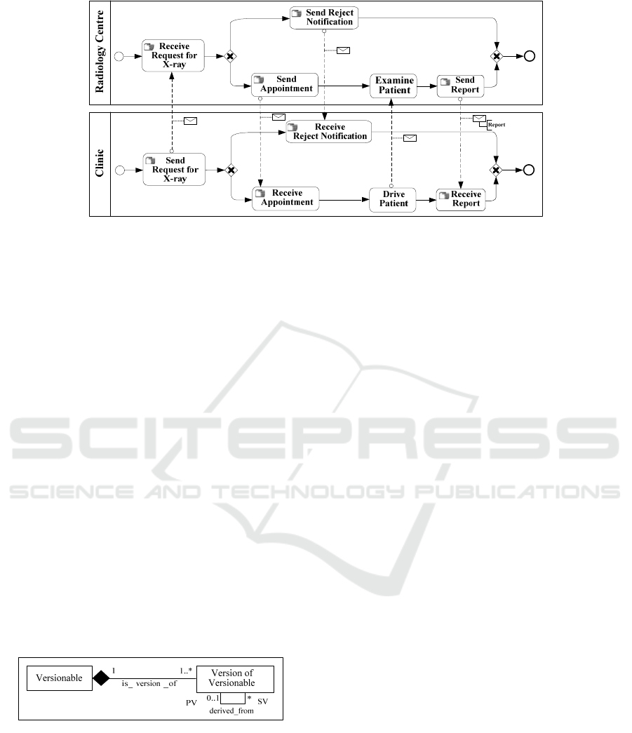
Figure 1: Version 1 of the Radiology Examination collaboration.
We introduce a versioning pattern to support
version modelling. The underlying idea is to model,
for each versionable class (a versionable class is a
class for which we handle versions) of the BPMN
meta-model for collaborations, both entities and
their corresponding versions. The versioning pattern
is given in Figure 2. Each versionable class is
described as a class, called Versionable. We
associate to each versionable class, a new class,
called Version of Versionable, whose instances are
versions of Versionable, and two links: (i) the
is_version_of composition, which links each
instance of the Versionable class with its
corresponding instances of the Version of
Versionable class; and (ii) the derived_from
relationship, which supports version derivation
hierarchy modelling. This latter relationship is
reflexive and the semantics of both relationship sides
is: (i) a version (SV) succeeds another one in the
derivation hierarchy and, (ii) a version (PV)
precedes another one in the derivation hierarchy.
Regarding versions, we also introduce attributes
such as version number, creator name, creation date
and state in the Version_of_Versionable class.
Figure 2: Versioning pattern.
3.2 BPMN4V: Extension of BPMN for
Collaboration Version Modelling
We model versions of collaborative processes
providing extensions to the BPMN 2.0 collaboration
meta-model previously presented. More precisely,
we use the previous versioning pattern to make some
classes of BPMN 2.0 collaboration meta-model
versionable. Figure 3 presents the resulting meta-
model, namely BPMN4V (BPMN for Versions).
BPMN 2.0 classes are visualised in white while
BPMN4V classes are visualised in grey.
In order to keep track of collaboration flexibility,
we propose to make some classes of BPMN2.0
meta-model versionable using the versioning pattern
introduced before. More precisely, we recommend
handling versions for the following BPMN 2.0
classes: Collaboration, Message, Process, Task and
Event. In fact, each of these classes represents key
concepts for collaborations and plays a strong role in
the definition of a collaboration. The idea is to keep
track of changes occurring to components which
play a part in the description of how the
collaboration is carried out.
Generally speaking, a new version of an element
(e.g., collaboration) is defined according to changes
occurring to it: these changes may correspond to the
addition of information (property or relationship) or
to the modification or the deletion of existing ones.
More precisely, regarding messages, we consider
that a modification of their property ItemDefinition
results in the creation of a new version of message.
For instance, if Report is a message referring to a
paper document (Itemkind value is physical), and as
a result of technical changes, if it becomes an
electronic document (Itemkind value is information)
then a new version of Report has to be created.
However we do not necessarily create a new version
of message if there is change in the interaction in
which the message is involved. Indeed an interaction
(i.e., a message flow) being defined as the triplet
(message, send node, receive node), where send and
receive nodes are interaction nodes involved in the
message exchange that either correspond to versions
of task or versions of event, changing the interaction
ICE-B 2016 - International Conference on e-Business
34
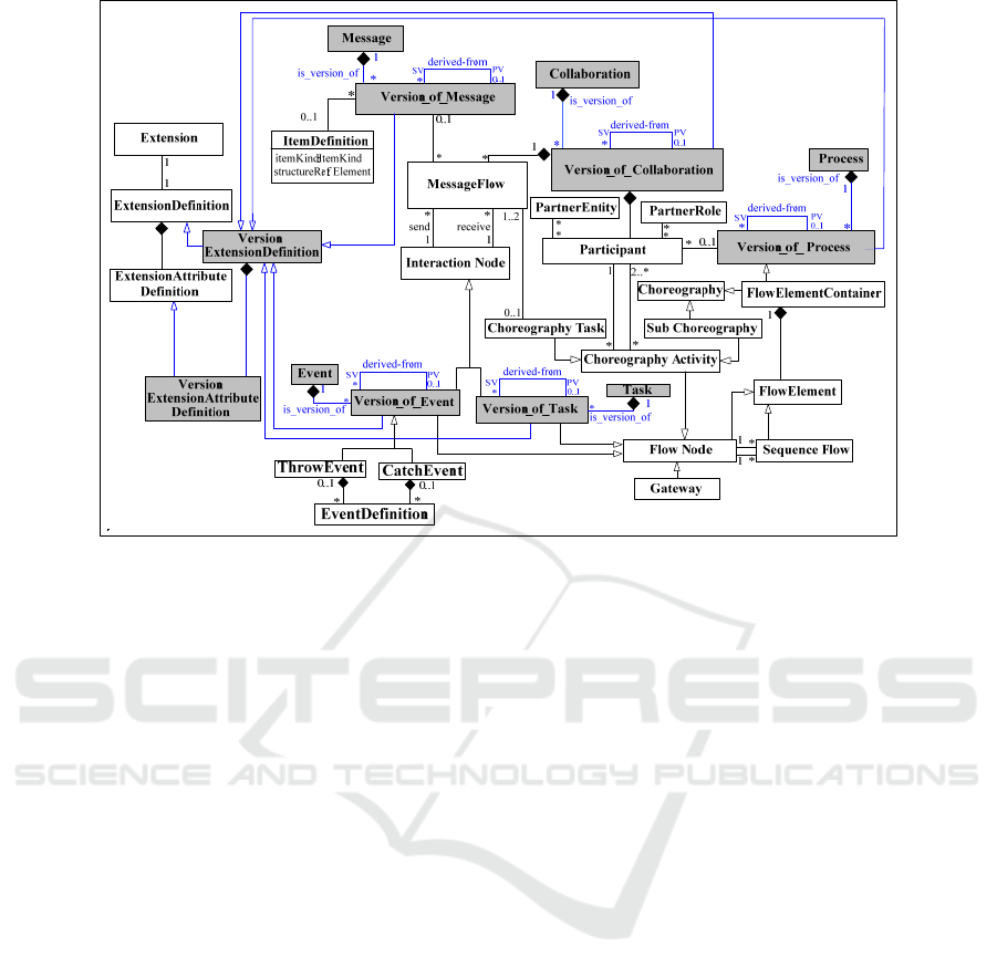
Figure 3: BPMN4V: extension of BPMN for version of collaboration modelling.
does not necessarily lead to the creation of a new
message. For instance, if message M is sent from
task A to task B, and if a new task C is defined after
an organizational change and the message is no
longer sent from A to B but rather from C to B, then
we do not create a new version of the message M if
it carries the same information. Thus we manage
M.v1 as a message exchanged between A and B, and
M.v1 and we also manage M.v1 as a message
exchanged between C and B.
Regarding processes, we create new versions
when there are changes to the involved tasks and/or
events or in the way they are linked together using
sequence flows and gateways. In the same way,
changes to tasks and events may result in the
creation of new task and event versions. In addition,
we create new versions of tasks or events involved
in message exchange, when there are changes to the
exchanged messages.
Finally, regarding collaborations, new versions
may result from changes to participants involved.
Thus when we add or delete a participant, it is
necessary to adapt the current collaboration to this
change: we have to incorporate the added participant
or to possibly replace the deleted one. New versions
of collaborations may also result from changes to
involved processes or exchanged messages.
Exchanged messages have an important impact in
collaboration flow. Thus any change in a sent or a
received message affects the involved tasks or
events, and consequently the involved process. So,
when we add (or delete) a message, we have to add
(or to delete) a received and a send activity, which
leads to changing the process schema. In this case,
the other processes involved in the collaboration
have in turn to be adapted to this change to ensure
continued collaboration.
On the other hand, BPMN 2.0 meta-model
provides extension mechanisms through classes
Extension, ExtensionDefinition and Extension
AttributeDefinition, and, as suggested in (OMG,
2011), each recommended extension has to be
assigned to these classes. Therefore, we recommend
adding the classes VersionExtensionDefinition and
VersionExtensionAttributeDefinition to model the
specific attributes which versionable classes include
(version number, creator name, creation date and
state). Thus each Version of Versionable class of the
meta-model is a sub-class of the abstract class
VersionExtensionDefinition.
3.3 BPMN4V Instantiation: Modelling
the Radiological Examination
Collaboration
Figure 4 gives an instantiation of BPMN4V for the
modelling of the first and third versions of the
Radiological Examination collaboration (C.v1 and
C.v3). In this figure, we model both the versions of
the collaboration and the versions of the two
processes involved in this collaboration.
A Version-based Approach to Address Flexibility of BPMN Collaborations and Choreographies
35
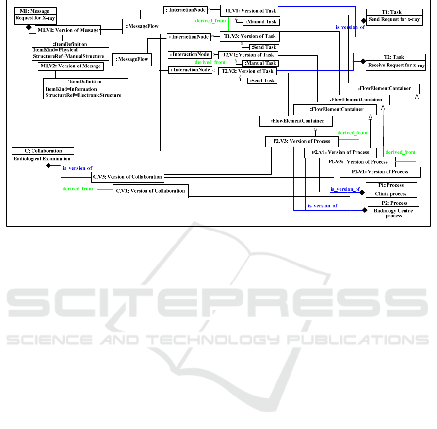
Figure 4: Instantiation of BPMN4V meta-model.
C.v1 and C.v3 differ from one another in their
partner processes, tasks type and message flows.
Thus we have defined two versions of the clinic
process, namely P1.v1 and P1.v3, each one defining
the behaviour of the clinic partner in each version of
the collaboration. We have also defined two versions
of the radiology centre process, namely P2.v1 and
P2.v3, each one defining the behaviour of the
radiological centre partner in each version of the
collaboration. P1.v1 and P2.v1 hold for the first
version of the collaboration C.v1 whereas P1.v3 and
P2.v3 hold for the third version C.v3.
Versions of processes involved in versions of the
Radiology Examination collaboration also differ
from one another in their component tasks and their
coordination. For instance, we have defined two
versions of the send task Send Request for X-ray.
The first one T1.v1 participates in P1.v1 whereas the
second one T1.v3 participates in P1.v2. T1.v3 has
been created first and T1.v3 has been derived from
T1.v1 since there is change in the task type.
Finally, Figure 4 defines the versions of
messages involved in the collaboration. For instance,
we have defined two versions of the message
Request for X-Ray. The first one M1.v1 holds for
C.v1 and refers to a paper document whereas the
second one, M1.v3, holds for C.v3 and refers to an
electronic document.
4 MAPPING VERSIONS OF
CHOREORGAPHIES
As indicated before, BPMN collaboration describes
both orchestration of partners activities and
messages exchanged, thus BPMN choreography can
be deduced from BPMN collaboration. For this
reason, we provide algorithms mapping versions of
collaborations into versions of choreographies
instead of directly model versions of choreographies.
This section presents our approach supporting the
mapping versions of collaborations into versions of
choreographies. It includes four steps:
Step 1 builds a VP-Tree for each version of
process involved in the considered version of
collaboration. Building a VP-Tree requires
breaking down each version of process into
fragments.
Step 2 links the VP-Trees built in the previous
step. More precisely, a Linked-VP-Tree is
composed of the VP-Trees of the considered
version of collaboration along with links
corresponding to messages exchanged.
Step 3 deduces the corresponding VC-Tree i.e.,
the corresponding version of choreography
represented as a tree.
Finally, step 4 deduces the corresponding
choreography, represented according to the
BPMN meta-model, from the VC-Tree.
ICE-B 2016 - International Conference on e-Business
36
The following sub-sections detail these four steps,
mainly providing the recommended algorithms for
each step.
4.1 From Versions of Collaborations to
VP-Trees
The first step of the approach consists of building
VP-Trees for each version of process involved in the
considered version of collaboration. To do so, we
decompose these versions of process into fragments
and we deduce the corresponding VP-Trees.
4.1.1 Process Fragmentation
Process fragmentation consists of decomposing each
version of process involved in the considered
collaboration into canonical single-entry single-exit
(SESE) fragments. To do so, we propose to use the
algorithm proposed by (Polyvyanyy et al., 2012) to
decompose a process model into canonical SESE
fragments. Figure 5 shows the result of SESE
decomposition for the Radiology Centre process of
the first version of the Radiological Examination
collaboration, according to (Polyvyanyy et al.,
2012)’s algorithm. This decomposition results in F0,
F1, and F2 SESE fragments. As the name suggests,
each SESE fragment has exactly one incoming and
exactly one outgoing edge. For instance, the internal
structure of fragment F2 is a sequence of tasks (Send
Appointment, Examine Patient, Send Report)
whereas fragment F1 consists of a branching of Send
Reject Notification task and F2 fragment.
Furthermore, SESE fragments can be embedded in
other SESE fragments: note how fragment F0
aggregates the Start Event, Receive Request for X-
ray task, F1 fragment and End Event to a SESE
fragment.
Examine
Patient
Send
Report
Receive
Request for
X-ray
Send Reject
Notification
Send
Appointment
F0
F1
F2
Figure 5: Canonical SESE fragments of the Radiology
Centre process.
To sum up, a fragment of a process version
involved in a version of collaboration is composed
of versions of tasks, start and end events, and
fragments synchronised by control patterns
(modelled as sequence flows or gateways).
4.1.2 Deducing VP-Trees from Fragments
VP-Trees are deduced from the identified fragments.
A VP-Tree is a tree having the following structure,
according to the ML language syntax.
VP-Tree::= VP-Node
VP-Node::= TerminalVP-Node |Non-
terminalVP-Node
Non-terminalVP-Node::= SEQ({VP-Node})|
CHC({VP-Node}) | PAR({VP-Node}) |
RPT(VP-Node)
TerminalVP-Node::= Task
A VP-tree is defined as a VP-node. We distinguish
two types of nodes: terminal nodes and non-terminal
nodes. A non-terminal node can be a sequence
(SEQ), a choice (CHC), a parallelism (PAR) or a
repetition (RPT) of –a set of– nodes. A terminal
node corresponds to a task (supporting message
exchange). Note that it is useless to keep the start
and end events of fragments. These events will be
added at step 4 when deducing the BPMN
choreography.
Our recommended algorithm, namely Build-VP-
Tree, implementing the mapping from a fragmented
version of process to its corresponding VP-Tree,
uses the mapping rules given in Table1.
Table 1: Mapping rules from Fragment to VP-Tree.
Fragment VP-Tree
Version of Task Task
Fragment Non-terminalVP-Node
Control Pattern
Nature of a Non-terminal VP-
Node (SEQ, CHC, PAR…)
Moreover, this algorithm uses the following set
of functions supporting the handling of both
fragments and trees:
isTask(f) returns true if the fragment f is a
version of task, otherwise false,
isEvent(f) returns true if the fragment f is an
event, otherwise false,
getComponents(f) returns the set of versions of
tasks, and/or fragments that compose the
fragment f,
getControlPattern(f) returns the control pattern of
the fragment f,
defineTerminalVP-Node(t) defines the terminal
VP-node corresponding to the task t,
defineNon-terminalVP-Node(f,p) defines the
non-terminal VP-node corresponding to the
fragment f synchronised by the control pattern p,
getCurrVP-Tree(vpt) returns the current node in
the VP-Tree vpt,
A Version-based Approach to Address Flexibility of BPMN Collaborations and Choreographies
37
addVP-Node(n,vpt,p) adds the VP-node n to the
VP-Tree vpt; n is added as a son of the node p.
The algorithm implementing this mapping is the
following.
Build-VP-Tree(f:Fragment):VP-Tree
Local n: VP-Node, vpt: VP-Tree
Begin
If IsTask(f) Then
n=defineTerminalVP-Node(f)
addVP-Node(n,vpt,
getCurrVP-Tree(vpt))
return vpt
Elseif not IsEvent(f) Then
/* f is a fragment */
n=defineNon-terminalVP-Node(f,
getControlPattern(f))
AddVP-Node(n,vpt,
getCurrVP-Tree(vpt))
For Each c in getComponents(f)
return Build-VP-Tree(c)
End For
End If
End
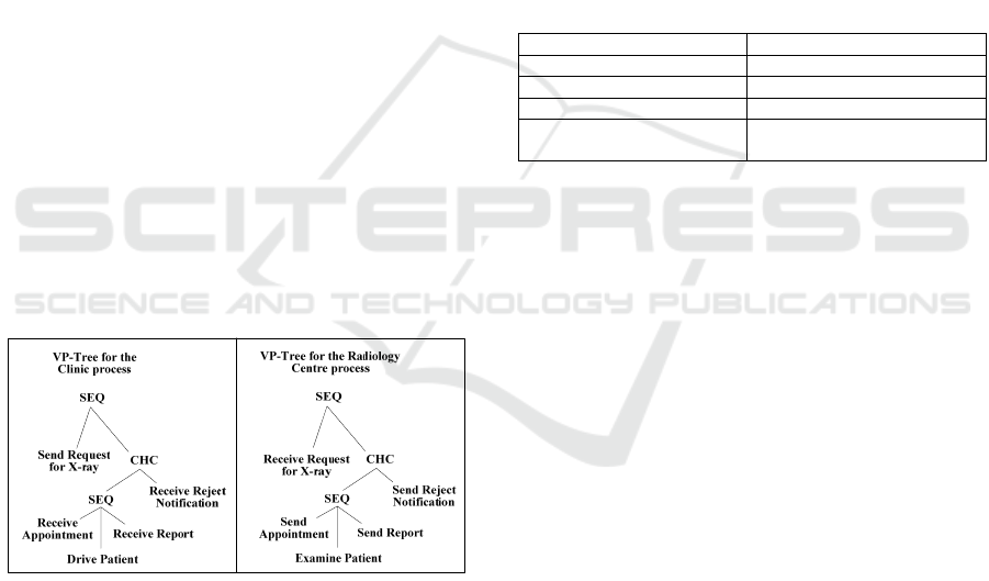
Figure 6 illustrates the result of this step with respect
to the first version of the Radiological Examination
collaboration. The previous algorithm has been
performed to each fragmented version of process
involved in the considered version of collaboration.
Each resulting VP-Tree is defined as a sequence of
terminal VP-nodes corresponding to versions of
tasks, and non-terminal VP-nodes corresponding to
embedded fragments.
Figure 6: VP-Trees for the first version of the Radiological
Examination collaboration.
4.2 From VP-Trees to
Linked-VP-Trees
The result of step 1 is a set of VP-Trees representing
versions of processes involved in the considered
version of collaboration. The second step of the
approach aims at linking these VP-Trees to capture
messages exchanged in the considered version of
collaboration. The result is a Linked-VP-Trees,
defined according to the following structure:
Linked-VP-Trees:= ({VP-Tree},{Link})
Link:= (SourceNode, TargetNode,
Message)
SourceNode := Task
TargetNode := Task
A Linked-VP-Trees involves a set of VP-Trees and a
set of links. A link is defined as the triplet
(SourceNode, TargetNode, Message), where the
source and target nodes are terminal VP-nodes, more
precisely tasks, involved in each involved VP-Tree
and the message is the information transmitted
between these nodes.
Our recommended algorithm for building
Linked-VP-Trees, namely Build-Linked-VP-Trees,
uses the mapping rules presented in Table 2.
Table 2: Mapping rules from Message flows to Linked-
VP-Trees.
Message flow Linked-VP-Trees
MessageFlow Link
sourceRef of MessageFlow SourceNode of a link
targetRef of MessageFlow TargetNode of a link
messageRef of
MessageFlow
Message of a link
Moreover, the proposed algorithm uses the
following set of functions supporting the handling of
message flows and Linked-VP-Trees:
getMessage(mf) returns the message
corresponding to the message flow mf,
getSourceNode(mf) returns the terminal VP-node
(more precisely the task) corresponding to the
source of the message flow mf,
getTargetNode(mf) returns the terminal VP-node
corresponding to the target of the message flow
mf,
addVP-Tree(t,lvpt) adds the VP-Tree t to the
Linked-VP-Trees lvpt,
addLink(l,lvpt) adds the Link l to the Linked-VP-
Trees lvpt,
defineLink(n1, n2, m) defines the link from the
terminal VP-node n1 to the terminal VP-node n2
and supporting the message m.
The algorithm implementing this mapping includes
two parameters corresponding to the considered set
of VP-Trees to be linked and to the list of message
flows exchanged between the corresponding
versions of processes.
Build-Linked-VP-Trees(setof-VPT: {VP-
Tree},setof-MF: {MessageFlow}):
Linked-VP-Trees
Local n1, n2: VP-Node, l: Link
ICE-B 2016 - International Conference on e-Business
38
mf: MessageFlow, vpt: VP-Tree
l-vpt: Linked-VP-Trees
Begin
For each vpt in setof-VPT
addVP-Tree(vpt,l-vpt)
End For
For Each mf in setof-MF
n1=getSourceNode(mf)
n2=getTargetNode(mf)
l=defineLink(n1,n2,
GetMessage(mf))
addLink(l,l-vpt)
End For
Return l-vpt
End
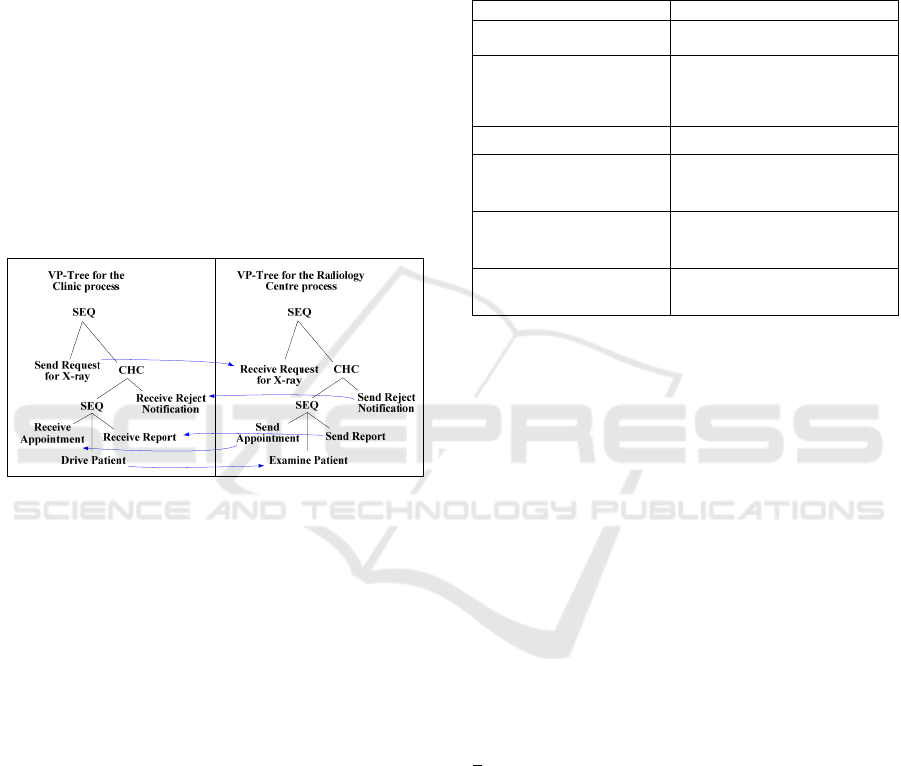
Figure 7 illustrates the result of this step with respect
to the first version of the Radiological Examination
collaboration, thus considering the two VP-Trees
presented in Figure 6. The different links of this
Linked-VP-Trees are shown as blue arrows.
Figure 7: Linked-VP-Trees for the first version of the
Radiological Examination collaboration.
4.3 From Linked-VP-Trees to VC-Tree
The third step of the approach deduces a VC-Tree
(Version of Choreography Tree) from the obtained
Linked-VP-Trees. A VC-Tree has the following
structure:
VC-Tree ::= VC-Node
VC-Node::= Non-terminalVC-Node |
TerminalVC-Node
Non-terminalVC-Node::= SEQ({VC-Node})|
CHC({VC-Node}) | PAR({VC-Node}) |
RPT(VC-Node)
TerminalVC-Node::= ChoreographyTask
ChoreographyTask::= (SenderParticipant,
Message, ReceiverParticipant)
A VC-Tree includes non-terminal VC-nodes and
terminal VC-nodes, which are choreography tasks.
A non-terminal VC-node can be a sequence (SEQ), a
choice (CHC), a parallelism (PAR) or a repetition
(RPT) of –a set of– VC-nodes. A choreography task
is defined as a triplet (SenderParticipant, Message,
ReceiverParticipant) indicating that a message is
sent from a participant to another one.
We detail in the following the recommended
algorithm for deducing VC-Trees. This algorithm,
namely Build-VC-Tree, uses the following mapping
rules.
Table 3: Mapping Rules from Linked-VP-Trees to VC-
Tree.
Linked-VP-Trees VC-Tree
Non-terminalVP-Node Non-terminalVC-Node
Nature of a Non-terminal
VP-Node (SEQ, CHC,
PAR…)
Nature of a Non-terminal VC-
Node (SEQ, CHC, PAR…)
Task and Link ChoreographyTerminalNode
Task source of a link
SenderParticipant of a
ChoreographyTerminalNode
Task target of a link
ReceiverParticipant of a
ChoreographyTerminalNode
Message of a link
Message of a
ChoreographyTerminalNode
Moreover, the proposed algorithm uses the
following set of functions supporting the handling of
Linked-VP-Trees and VC-Trees:
isTask(n) returns true if the VP-node n is a task,
otherwise false,
getLink(n) returns the link in which the VP-node
n is involved,
getSource(l) returns the terminal VP-node source
of the link l,
getReceiver(l) returns the terminal VP-node
corresponding receiver of the link l,
getMessage(l) returns the message of the link l,
father(n) returns the non-terminal VP-node
which is the father of the node n if n is not root
of the VP-Tree, otherwise it returns n,
brother(n) returns the VP-node which is a brother
of the VP-node n,
nextChild(n) returns the VP-node corresponding
to the next child of the VP-node n
goingOnBrowsing(n) returns true if we have to
go on browsing the sub-tree that the VP-Node n
belongs to, otherwise false,
listOfChildren(n) returns the children of the non-
terminal VP-Node n,
getControlPattern(n) returns the control pattern
of the non-terminal VP-node n,
getCurr(vct) returns the current node in the VC-
Tree vct,
defineChoreographyTask(n1,m,n2) defines a
A Version-based Approach to Address Flexibility of BPMN Collaborations and Choreographies
39

choreography task which will be added to the
VC-Tree to be build: n1 is the sender participant,
m is the message to be send and n2 is the
receiver participant,
defineNon-terminalVC-Node(n,p) defines the
non-terminal VC-Node corresponding to the
non-terminal VP-Node n synchronised by the
control pattern p,
addVC-Node(n,vct,p) adds the VC-Node n to the
VC-Tree vct as a son of the non-terminal VC-
Node p.
The algorithm implementing this mapping is the
following. It includes a single parameter which
corresponds to a node of one of the VP-Trees of the
mapped Linked-VP-Trees. The first value for this
parameter is
root(initial(l-vpt)), which
corresponds to the root of the initial VP-Tree of the
mapped Linked-VP-Trees l-vpt. In the considered
example (cf. Figure 5), the initial VP-Tree is the VP-
Tree of the Clinic process.
Global vct: VC-Tree
Build-VC-Tree(n: VP-Node)
Local n2: VP-Node, l:Link, m: Message
ctn: Non-terminalVC-Node
Begin
If isTask(n) Then
l=getLink(n): m=getMessage(l)
If n=getSource(l) then
n2=getReceiver(l)
Else
n2=getSource(l)
n=getReceiver(l)
End If
/* we define a choreography
task ct and its corresponding
non-terminal VC- Tree node ctn */
ct=defineChoreographyTask(n,m,n2)
ctn=defineNon-terminalVC-Node(
father(n2),getPattern(father(n2))
/* we add these nodes to vct */
addVC-Node(ctn,vct,getCurr(vct))
addVC-Node(ct,vct,getCurr(vct))
If goingOnBrowsing(n2) Then
/* we go on browsing */
Build-VC-Tree(brother(n2))
End If
Else
/* n is a non-terminal VP-Tree
node: we define its corresponding
non-terminal VC-Tree node */
ctn=defineNon-terminalVC-Node(
father(n),getPattern(father(n))
/* we add this node to vct */
addVC-Node(ctn,vct,getCurr(vct))
/* we go on browsing */
Switch getPattern(n)
SEQ, RPT:
Build-VC-Tree(nextChild(n))
Break
CHC, PAR:
For c in listOfChildren(n)
Build-VC-Tree(c)
End For
End Switch
End If
End
Figure 8 illustrates the result of this step with respect
to the first version of the Radiological Examination
collaboration, thus considering the Linked VP-Trees
previously presented in Figure 7. Each triplet
corresponds to a choreography task of the VC-Tree
thus defining respectively its sender participant, its
message and its receiver participant.
Figure 8: VC-Tree for the first version of the Radiological
Examination collaboration.
Note that the deduced VC-Tree have to be
reduced to delete the control patterns unnecessarily
added to the VC-Tree. For instance, the following
VC-Tree SEQ(A,SEQ(B)) have to be reduced to
SEQ(A,B). Due to lack of space, we do not detail the
algorithm implementing this reduction.
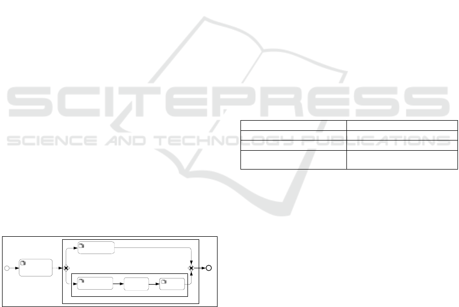
4.4 Deducing Versions of
Choreographies
The final step of the approach deduces BPMN
choreographies from VC-Trees. The recommended
algorithm implementing the mapping from VC-Tree
to BPMN choreography uses the mapping rules
given in Table 4. More precisely, Table 4 indicates
that choreography terminal nodes of VC-Tree
correspond to Choreography Task of BPMN
choreography whereas non-terminal nodes of VC-
Tree, and more particularly the nature of these nodes
(SEQ, CHC, PAR, RPT) helps in identifying the
BPMN coordination pattern, defined using sequence
flows and/or gateways. Note that we obviously
specify a start event and an end event in the deduced
BPMN choreography.
ICE-B 2016 - International Conference on e-Business
40
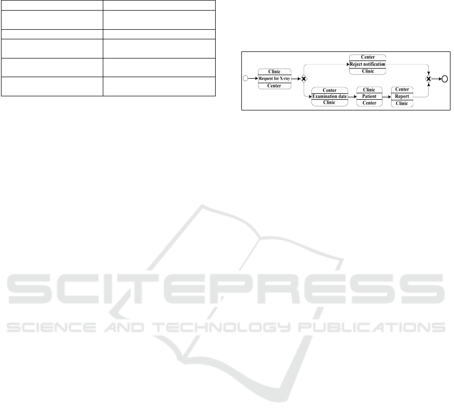
Table 4: Mapping rules from VC-Tree to BPMN
Choreography.
VC-Tree BPMN Choreography
Non-terminalVC-Node
BPMN control pattern: Sequence
Flow and/or Gateway
ChoreographyTask BPMN ChoreographyTask
SenderParticipant of a
ChoreographyTask
Initiating participant of BPMN
ChoreographyTask
ReceiverParticipant of a
ChoreographyTask
Participant of BPMN
ChoreographyTask
Message of a
ChoreographyTask
name of a BPMN
ChoreographyTask
Our recommended algorithm, namely Build-
Choreography, uses the following set of functions
supporting the handling of both VC-Tree and BPMN
choreography:
isChoreographyTerminalNode(n) returns true if
the VC-Node n is a choreography terminal node,
otherwise false,
listOfChildren(n) returns the children of the non-
terminal-VC-Node n,
defineChoreographyTask(n) defines the BPMN
choreography task corresponding to the
choreography terminal node n,
definePattern(n) defines the BPMN control
pattern (gateway, sequence flow) corresponding
to the nature of the non-terminal-VC-Node n,
addChoreographyTask(t,c) adds the BPMN
choreography task t to the BPMN choreography
c,
addControlPattern(p,c) adds the BPMN pattern p
to the BPMN choreography c.
The algorithm implementing this mapping is the
following.
Build-Choreography (vct: VC-Tree):
BPMN-Choreography
Local t: BPMN-ChoreographyTask
p: BPMN-ControlPattern
ch: BPMN-Choreography
c: VC-Tree
Begin
If
isChoreographyTerminalNode(vct)Then
t = defineChoreographyTask(vct)
addChoreographyTask(t,ch)
return ch
Else
-- vct is a non-terminal-VC-node
pa = definePattern(vct)
addControlPattern(p,vct)
For Each c in listOfChildren(vct)
return Build-Choreography(c)
End For
End If
End
Figure 9 illustrates the result of this step with
respect to the first version of the Radiological
Examination collaboration thus considering the VC-
Tree previously presented in Figure 8. Note that a
start and an end event have been added to the
resulting choreography.
Figure 9: BPMN choreography for the first version of the
Radiological Examination collaboration.
5 CONCLUSION
This paper has addressed BPMN collaborations and
choreographies flexibility using versions. More
precisely it has extended the BPMN meta model for
collaboration to support collaboration versioning.
Then it has introduced a set of algorithms
implementing a four step approach for mapping
versions of collaborations to corresponding versions
of choreographies.
Our contribution addresses an important issue in
the BPM area which is Inter-organisation Process
(IoP) flexibility. Indeed, process flexibility has been
mainly considered in an intra organisational context.
In such a context, several contributions have
addressed one or several flexibility needs: for
instance, (Rosemann et al., 2007) and (Hallerbach et
al., 2010) dealt with intra-organisational process
variability using variants, while (Adams et al., 2007)
addressed intra-organisational process adaptation
and more precisely exception handling for processes.
We also found contributions advocating versioning
to deal with process flexibility needs and more
precisely process variability, evolution and
adaptation: e.g., (Ekanayake et al., 2011), (Zhao and
Liu, 2013), (Ben Said et al., 2014). More
particularly, (Ben Said et al., 2014) proposed to
extend BPMN to model versions of private
processes, considering thus only processes internal
to a single company.
On the other hand, process flexibility has been
rather neglected in the context of Inter-
organisational Processes (IoPs). However, we have
found two main contributions dealing with this
issue. Firstly (Fdhila et al., 2015) addressed change
propagation from a partner process towards the
processes of the other partners involved in a
collaboration or in a choreography. More precisely,
A Version-based Approach to Address Flexibility of BPMN Collaborations and Choreographies
41

they provide a set of algorithms to deal with changes
of process schema by adding, deleting, replacing or
updating process fragments, but they do not consider
changes that can affect messages (i.e., information)
exchanged between process partners. Moreover, this
contribution does not exactly deal with the issue
addressed in this paper which is how to model
collaborations or choreographies able to deal with
IoP variability, adapation and evolution. Secondly,
(Boukhedouma et al., 2013) proposed a service-
based approach to model IoPs by combining
processes and SOA. More precisely, they provide
high-level patterns for service (adding, removing,
substituting services), control flow and interaction
adaptation. Note that this contribution addresses IoP
evolution but it does not address IoP variability and
adaptation. Thus IoP flexibility is still an open issue
and we believe our contribution, which extends (Ben
Said et al., 2014) considering versions of processes
crossing the boundaries of companies, to be a step
forward in addressing the flexibility of BPMN
collaborations and choreographies.
However this contribution has the following
drawbacks, which will be addressed in future works.
Firstly this paper has extended BPMN to model
versions of collaborations and has proposed
algorithms to deduce the corresponding versions of
choreographies. This choice is mainly due to BPMN
collaborations, which subsume choreographies,
highlighting both the orchestration of involved
partners activities and messages exchanged.
However, BPMN practitioners can also directly
model choreographies without modelling
corresponding collaborations: thus we also have to
extend BPMN to directly model versions of
choreographies. The second drawback is related to
the algorithms supporting the mapping from version
of collaborations into versions of choreographies.
These algorithms are based on the following
assumption: the mapped versions of collaboration
have to be consistent in that they do not include any
dead-lock, cycle and so on. On the other hand, the
recommended algorithms take into account neither
intermediate events of collaboration versions, nor
events source or target of message flows. Finally
these algorithms have to be implemented and
evaluated. Their implementation is in progress and
their evaluation will be addressed shortly.
REFERENCES
Reichert, M., Weber, B., 2012. Enabling Flexibility in
Process-Aware Information Systems: Challenges,
Methods, Technologies, Springer.
Rosemann, M., van der Aalst, W., 2007. A Configurable
Reference Modeling Language. Information Systems,
vol. 32, n°1, pp. 1–23.
Hallerbach, A., Bauer, T., Reichert, M., 2010. Capturing
Variability in Business Process Models: the Provop
Approach. Software Maintenance, vol. 22, n°6-7, pp.
519–546.
Adams, M., ter Hofstede, A., Edmond, D., van der Aalst,
W., 2007. Dynamic and Extensible Exception
Handling for Worklows: a Service-Oriented
Implementation. Int. Conference on Cooperative
Information Systems, Vilamoura, Portugal, pp. 95–
112.
Ekanayake, C., La Rosa, M., ter Hofstede, A., Fauvet,
M.C., 2011. Fragment-based Version Management for
Repositories of Business Process Models. Int.
Conference on Cooperative Information Systems,
Hersonissos, Crete, Greece, pp. 20–37.
Zhao, X., Liu, C., 2013. Version Management for
Business Process Schema Evolution. Information
Systems, vol. 38, n°8, pp. 1046–1069.
Chebbi. I., Dustdar S., Tata, S., 2006. The View-based
Approach to Dynamic Inter-Organizational Workflow
Cooperation. Data Knowledge Engineering, vol. 56,
no. 2, pp. 139–173.
Ben Said, I., Chaâbane, M.A., Bouaziz, R., Andonoff, E.
2014. Context-Aware Adaptive Process Information
Systems: The Context-BPMN4V Meta-Model. Int.
Conference on Advances in Databases and
Information Systems, Ohrid, Macedonia, pp. 366–382.
OMG, 2011. Business Process Model and Notation
(BPMN) Version 2.0. OMG Document Number:
formal/2011-01-03, available at: http://www.omg.org/
spec/BPMN/2.0.
Fdhila, W., Indiono, C., Rinderle-Ma, S., Reichert, M.,
2015. Dealing with Change in Process
Choreographies: Design and Implementation of
Propagation Algorithms. Information Systems, vol. 49,
pp. 1–24.
Polyvyanyy, A., Garcia-Banuelos, L., Dumas, M., 2012.
Structuring Acyclic Process Models. Information
Systems, Vol. 37, n° 6, pp. 518–538.
Boukhedouma, S., Oussalah, M., Alimazighi, Z., Tamzalit,
D., 2013. Adaptation Patterns for Service-based Inter-
Organizational Workflows. Int. Conference on
Research Challenges in Information Systems, Paris,
France, May 2013, pp. 1–10.
ICE-B 2016 - International Conference on e-Business
42
