
A Template Attack Against VERIFY PIN Algorithms
H
´
el
`
ene Le Bouder
1
, Thierno Barry
2,3
, Damien Courouss
´
e
2,3
,
Jean-Louis Lanet
1
and Ronan Lashermes
1
1
LHS-PEC TAMIS, INRIA, Campus Beaulieu 35042, Rennes, France
2
Univ. Grenoble Alpes, 38000, Grenoble, France
3
LIST, CEA, MINATEC Campus, 38054, Grenoble, France
Keywords:
Template Attack, Side Channel Analysis, Electromagnetic Emission, VERIFY PIN Algorithm, Embedded
Systems’ Security.
Abstract:
This paper presents the first side channel analysis from electromagnetic emissions on VERIFY PIN algorithms.
To enter a PIN code, a user has a limited number of trials. Therefore the main difficulty of the attack is to
succeed with very few traces. More precisely, this work implements a template attack and experimentally
verifies its success rate. It becomes a new real threat, and it is feasible on a low cost and portable platform.
Moreover, this paper shows that some protections for VERIFY PIN algorithms against fault attacks introduce
new vulnerabilities with respect to side channel analysis.
1 INTRODUCTION
In many smart cards, a Personal Identification Num-
ber (PIN or PIN code) is used to authenticate the user.
These PIN codes are used, for example, in payment
cards or SIM cards. Hence, they are targets of choice
for malicious adversaries. When discussing about the
security of embedded devices, a critical aspect is: the
interaction of the computing unit with its physical
environment. This interaction is used by physical
attacks.
State of the Art
The physical attacks are mainly divided in two fami-
lies: the Side Channel Analysis (SCA) and the Fault
Injection Attacks (FIA).
FIA consist in disrupting the circuit behavior
(with EM pulse, laser, clock glitch...). VERIFY PIN
algorithms are designed to resist FIA such as (Moro
et al., ; Riviere et al., ).
SCA are based on observations of the circuit be-
havior during the computation. They exploit the fact
that some physical values of a circuit depend on in-
termediary values of the computation. This is the so-
called information leakage of the device. The most
classic leakages are timing (Kocher, 1996), power
consumption (Mangard et al., 2008a; Mangard, )
and electromagnetic emissions (EM) (Quisquater and
Samyde, 2001). VERIFY PIN algorithms are de-
signed to resist timing attacks (Foo Kune and Kim,
2010). To the best of our knowledge, there is no pub-
lished work on EM analysis against VERIFY PIN al-
gorithms.
In this paper we are interested in statistical
categorizations more precisely template attacks.
Templates were introduced as the strongest side
channel attack possible from an information theoretic
point of view (Chari et al., 2003). They have been
used in many attacks, such as (Archambeau et al.,
; Elaabid et al., 2007; Oswald and Mangard, 2006;
Rechberger and Oswald, 2005) since.
Motivation
The most classical SCA are Correlation Power
Analysis (CPA) (Brier et al., 2004). In these attacks
many traces are required to break the secret. But in
a PIN code, a user has a limited number of trials, so
an attacker can exploit only a few EM traces. This is
a major difficulty, which explains why there are no
known CPA attacks on PIN codes. The ultimate goal
of our work is to test the resistance of a VERIFY PIN
against a SCA with only few traces. That is why we
are interesting by Template attacks.
Contribution
This paper presents what is, to the best of our knowl-
edge, the first EM SCA attack on VERIFY PIN al-
gorithms. We have chosen to study template attacks
Bouder, H., Barry, T., Couroussé, D., Lanet, J-L. and Lashermes, R.
A Template Attack Against VERIFY PIN Algorithms.
DOI: 10.5220/0005955102310238
In Proceedings of the 13th International Joint Conference on e-Business and Telecommunications (ICETE 2016) - Volume 4: SECRYPT, pages 231-238
ISBN: 978-989-758-196-0
Copyright
c
2016 by SCITEPRESS – Science and Technology Publications, Lda. All rights reser ved
231

because they can be effective with only one trace.
Template analyzes are statistical categorizations
divided in two steps: a profiling phase and an attack
phase. Because of this, the attacker can perform the
first phase ahead of time. And then the attack phase
becomes extremely fast because only few traces are
used. The experimental bench can be purchased at a
very low cost and can be portable.
Additionally this paper shows that some counter-
measures against FIA can introduce new vulnerabili-
ties in SCA.
Organization
This paper is organized as follows. The section 2 de-
scribes the target implementation. The attack is de-
tailed in section 3. The experimental set-up and the
results are presented in section 4. Finally the conclu-
sion is drawn in section 5.
2 IMPLEMENTATION OF THE
TARGET: VERIFY PIN
ALGORITHM
In our settings, a PIN code is an array of 4 bytes in-
dexed by b (b ∈[[0, 3]]), where each byte can take up to
10 values. The set of these values is noted K = [[0, 9]].
So, there are 10
4
different PIN codes.
A PIN code is used to authenticate a user. A par-
ticular PIN, called true PIN, noted U is embedded in
the smart card, and only its rightful owner knows this
true PIN value. The protocol to authenticate a user is
as follows. A user proposes a PIN called candidate
PIN, noted V , to the device (smart-card). A VERIFY
PIN algorithm compares the candidate PIN and the
true PIN. A candidate PIN is valid if and only if it is
equal to the true PIN (U = V). In that case, the user is
authenticated.
In theory, the correct user should always propose
a valid candidate PIN, but a human error is still pos-
sible. That is why in practice, in a VERIFY PIN al-
gorithm, the user has several trials, number noted C.
Usually it is 3 in a SIM card or a payment card, but it
is possible that more tries are authorized, for example
in an electronic lock. In the device, there is a ratifi-
cation counter which decreases when a failed candi-
date PIN is tested. This counter is reset to the original
value when a valid candidate PIN is proposed. If it is
equal to zero, the device is blocked; nobody can use
it again. We emphasize the fact that an attacker has to
keep a trial to be authenticated. It is of no interest to
retrieve a PIN code if the device is blocked.
In our attack, the implementation of VERIFY PIN
Algorithm 1: Simplified VERIFY PIN.
1: procedure VERIFY PIN(candidate PIN V )
2: counter = counter −1
3: if counter > 0 then
4: status = COMPARISON(U,V )
5: status
2
= COMPARISON(U,V )
6: if status 6= status
2
then
7: ERROR, device is blocked
8: else
9: if status = TRUE then
10: counter initialized at original
value: C
11: end if
12: end if
13: else
14: device is blocked
15: end if
16: return status
17: end procedure
Algorithm 2: Comparison of two PIN codes.
1: procedure COMPARISON(candidate PIN V , true
PIN U)
2: status = FALSE
3: diff = FALSE
4: fake = FALSE
5: for b = 0 to 3 do
6: if U
b
6= V
b
then
7: diff = TRUE
8: else
9: fake = TRUE
10: end if
11: if (b = 3) and (diff = FALSE) then
12: status = TRUE
13: else
14: fake = TRUE
15: end if
16: end for
17: return status
18: end procedure
proposed by (Riviere, 2015) is chosen. This im-
plementation respects the verifications of (Folkman,
2007). But, to clarify our description only a very sim-
plified version is described in Algorithm 1.
A classic countermeasure against FIA is to com-
pare the candidate PIN with the true PIN twice, as in
Algorithm 1 at line 4 and line 5. This countermea-
sure doubles the opportunities of leakage on COM-
PARISON, as shown in the Table 1.
In our case, the attacker focuses on leakages from
the COMPARISON algorithm. The algorithm used in
SECRYPT 2016 - International Conference on Security and Cryptography
232

this paper is described in COMPARISON Algoritm 2.
To resist the timing attack (Foo Kune and Kim,
2010; Kocher, 1996), the comparison between the
true PIN U and the candidate PIN V has to be in a
constant time. All bytes have to be compared even if
the previous bytes are false. The computation time for
a valid candidate PIN or a false candidate PIN has to
be the same.
Table 1: Number of traces corresponding to COMPARISON,
obtained by the attacker according to the implementation of
VERIFY PIN, C is the number of trials.
Implementation C = 2 C = 3
1 COMPARISON 1 trace 2 traces
2 COMPARISON 2 traces 4 traces
3 DESCRIPTION OF THE
ATTACK
3.1 Preliminaries
Generally template attacks are used against crypto-
systems, but to the best of our knowledge, it is the first
time they are tested with a VERIFY PIN algorithm.
To implement a template attack, a pair of identical
devices is needed. One is called the profiling device,
the attacker has full control of it; and the other is the
targeted device.
The first step, called profiling phase, is to build a
physical model of the EM traces for all possible se-
cret values with the profiling device. A model for
one value is called a template. After that, the attack
phase starts by obtaining traces on the targeted device.
These traces are confronted to the different templates.
In our attack, it is assumed that the attacker has the
same device as the targeted device, where true PIN is
known. She can obtain all the desired measurements
on the profiling device, only a valid candidate PIN is
proposed after every other candidate PIN. Namely she
can:
• obtain one trace on the targeted device;
• change the true PIN in her profiling device;
• obtain many traces on her profiling device.
In this way, it is possible to build a template attack on
VERIFY PIN algorithms.
The attack is divided in two parts and six steps.
The profiling phase is split in:
1. Campaign on the profiling device,
2. Detection of the points of interest,
3. Building templates.
The attack phase is split in:
4. Campaign on the targeted device,
5. Confrontation between measurements,
6. Discrimination of one guess.
In this template attack, 3 PIN codes are considered.
The true PIN in the targeted device is noted U and the
true PIN in the profiled device is noted U
0
. The goal
of the attack is to learn U . The candidate PIN is the
same in the profiling phase and in the attack phase and
it is noted V .
In SCA a divide and conquer approach is gener-
ally chosen; so in this case only one secret byte is
retrieved at a time. So the target is a byte U
b
. A guess
on a byte U
b
(b ∈[[0, 3]]) is noted k ∈K; and v denotes
the value of V
b
.
3.2 The Profiling Phase
Step 1: Campaign on the Profiling Device
The profiling phase consists in collecting many traces
on the profiling device, for the purpose of building
templates. A campaign is for one given byte b.
• The byte U
0
b
of the true PIN takes all values k in K
and the other PIN bytes stay to zero.
• The candidate PIN byte V
b
is always fixed to a
chosen value v.
For each guess k, the attacker acquires a campaign
of n curves with a true PIN byte U
0
b
fixed to k and
candidate PIN byte fixed to v, (U
0
b
= k and V
b
= v).
Step 2: Detection of Points of Interest
A window of points of interest, denoted PoI, is a set
of points of a trace such as information on the secret
can be retrieved from them. They are the moment of
information leakage.
The first step of the traces treatment is to detect the
PoI. In our case, it is first to detect in the VERIFY PIN,
when the COMPARISON (Algorithm 2) is computed.
To respect a divide and conquer approach, the sec-
ond step is to find where each comparison for each
byte occurs in a trace of COMPARISON.
A time window is selected for each byte to
perform the template attack byte per byte. If this
step is not performed, in the best case, the attacker
can retrieve the values of all the bytes but she cannot
put them in the right order, so the attack fails.
Generally it is possible to detect the PoI where the
difference between the means of the template traces
are the most significant or using variance analysis as
in (Linge et al., ). In our implementation the bytes
of a candidate PIN V are tested one after another.
So, in practice a trigger signal is put around the
A Template Attack Against V ERIFY PIN Algorithms
233

COMPARISON and the traces are split in 4.
Step 3: Building Templates
In this paragraph, the attacker has selected a good PoI
window on traces for each byte, to respect a divide
and conquer approach.
The attacker obtains a matrix M
v,k
=
xk
(i, j)
,
with i ∈[[0, n]] and j ∈[[0, p]]; n is the number of traces
and p the number of points in a trace. The column
vector j of M
v,k
is noted xk
j
and xk
j
is the mean of
this vector. The mean vector is noted xk =
xk
j
.
xk
j
=
1
n
n
∑
i=1
xk
i, j
.
Template attacks apply advanced statistical methods.
However, in this paper the optimizations presented
in (Choudary and Kuhn, 2014), are used.
The first step is to compute the covariance matrix
S
v,k
, a square matrix of size p · p. The elements of
S
v,k
=
sk
( j, j
0
)
are computed with equation (1)
1
.
sk
( j, j
0
)
=
1
n −1
·
xk
j
−xk
j
t
xk
j
0
−xk
j
0
. (1)
3.3 Attack Phase
Step 4: Campaign on the Targeted Device
During this step the attacker obtains one trace such
that:
• the value of the true PIN byte U
b
is unknown, it is
the target;
• the candidate PIN byte V
b
is equal to v.
The trace is a vector T
v
= {xt
j
}
j∈[[0,p]]
of p points. Of
course T
v
corresponds at a good windows of PoI.
Step 5: Confrontation Between Measurements
The goal of the attack is to confront the trace T
v
to the
template matrix S
v,k
.
In SCA, it is classic to suppose that the electronic
noise at each point of a power trace is normally dis-
tributed as described in (Mangard et al., 2008b). So
the probability density function f
v
, given S
v,k
and xk
is computed with (2)
2
.
f
v
T
v
|S
v,k
, xk
=
1
√
2π
p
|S
v,k
|
exp
−
1
2
T
v
−xk
S
−1
v,k
T
v
−xk
t
(2)
As explained in (Choudary and Kuhn, 2014), several
problems appear when implementing the template at-
tack, so our attack follows their given advices. The
1
M
t
means transposed of M.
2
|M| is the determinant of M
logarithm is used for the multivariate normal distribu-
tion in (3),
F
v
(T
v
, k) = ln
f
v
T
v
|S
v,k
, xk
=
−
1
2
ln(|S
v,k
|) +
T
v
−xk
·S
−1
v,k
·
T
v
−xk
t
+ c
(3)
where c is a constant,
c = −p ·ln (2π) . (4)
Moreover, the logarithm of the determinant is com-
puted with the equation (5),
ln(|S
v,k
|) = 2 ∗
∑
d
ii∈diag(D)
ln(d
ii
) ; (5)
where D is the Cholesky decomposition of S
v,k
:
S
v,k
= D
t
·D .
One has to remark than D can be pre-computed in
the profiling phase. In this paper, this way is used to
compute F
v
.
Step 6: Discriminating Guesses
The attack returns the guess k
v
for which F
v
is max-
imal for a given T
v
. This guess maximizes F
v
as in
equations (6). Let max
−1
be the function that returns
the fiber of the maximum.
max
k∈K
(F
v
(T
v
, k)) = F
v
(T
v
, k
v
)
max
−1
k∈K
(F
v
(T
v
, k)) = k
v
. (6)
The attack succeeds if the guess, noted k
v
defined
in (6) is equal to the real value of U
b
.
It is possible to rank the guesses k according to
the value of F
v
(T
v
, k). If the attack fails, it shows how
well the correct value U
b
is ranked.
4 EXPERIMENTAL RESULTS
4.1 Acquisition Protocol of EM Traces
Once the theoretical framework has been setup, an
experimental benchmark was performed. The VER-
IFY PIN algorithm is implemented on an ARM-
based STM32-F100RB micro-controller embedding a
Cortex-M3 core and running in our case at 24MHz.
The board used is the STM32VLDICOVERY. This
chip does not embed any countermeasures against
side channels but it is a popular choice for Internet
Of Things (IoT) applications.
The experimental bench is composed of a control
computer, a 3405A Picoscope and an EM probe. The
experimental bench is described in Fig. 1.
SECRYPT 2016 - International Conference on Security and Cryptography
234
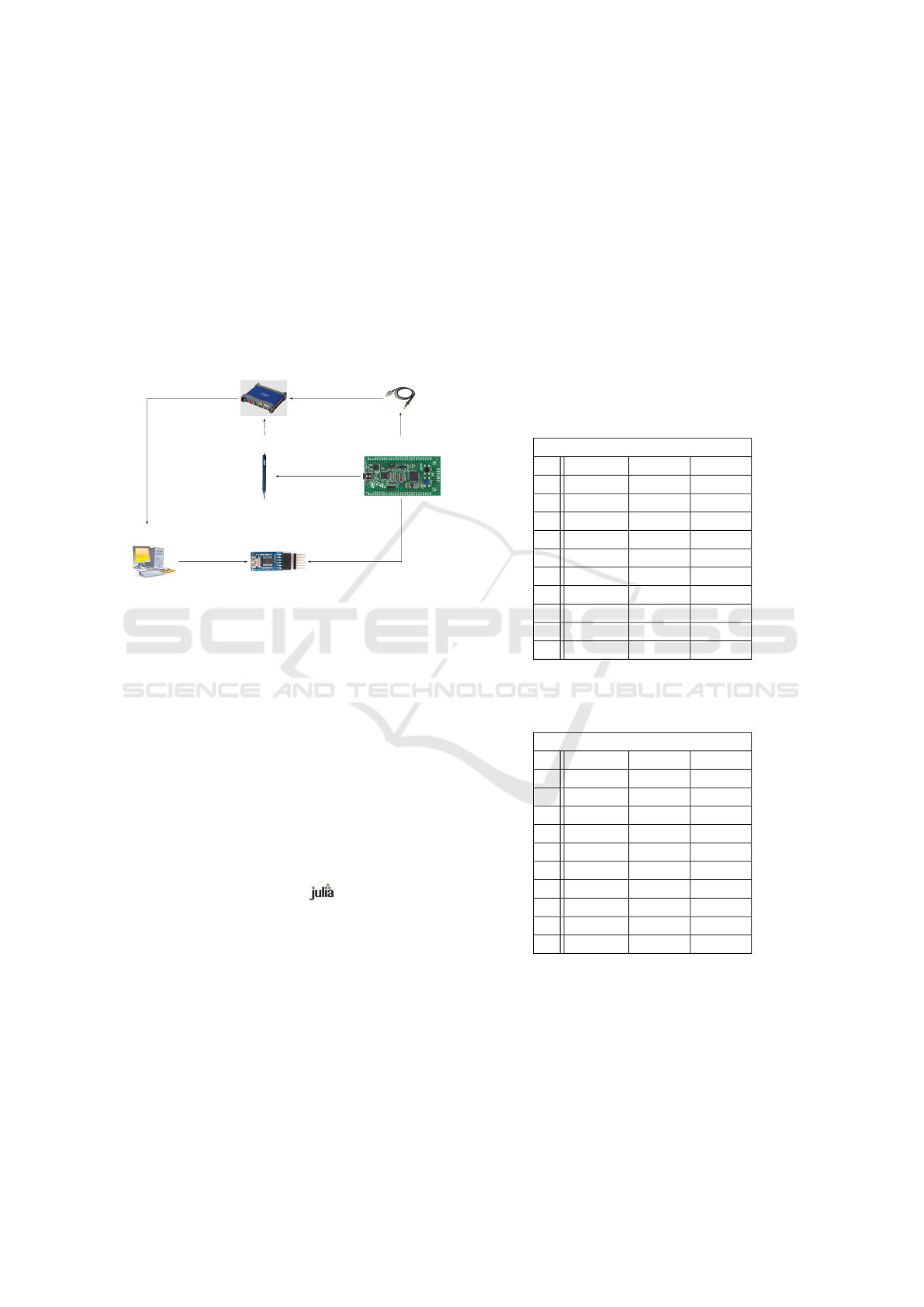
1. The STM32 sends (via an USB/UART
FTTDI232) that it is ready to test a PIN
code, to the computer.
2. Still via the UART, the computer sends the PIN
candidate to the STM32.
3. A trigger signal measured by the Picoscope means
that the STM32 tests the PIN candidates.
4. The probe and the Picoscope measure the EM
leakage and store the traces.
5. The Picoscope sends the traces to the computer.
Picoscope
Probe
EM Probe
Target Device
UART
Control computer
5. send ”Ok the curves are saved”
1. send ”Ok ready”
2. send candidate PIN
3. receive the trigger
4. measurements
Figure 1: Experimental bench.
The EM probe from Langer (RF-R0,3-3) is used
to measure the signal. This last one is amplified
by a Preamplifier from Langer (PA 303), before the
measurements by the Picoscope 3405A (USB oscil-
loscope). The bandwidth of the measurement setup
is limited by the Picoscope with an upper frequency
of 100MHz. The traces obtained are composed of
p = 3700 points, with a 1GS/s sampling rate. We
remind that 100MHz is a cutoff frequency marking
an attenuation of the relevant signal, not its total re-
moval.
One has to remark that the required equipment
comes at a very low cost, under 2000¤ excluding the
computer.
The computation heavy step is the profiling phase.
The program is written with the language (Bezan-
zon et al., ), which is particularly efficient for
computing-intensive tasks. Considering the large size
of the covariance matrices, the computation requires a
lot of memory. To create 10 templates (for guesses in
K = [[0, 9]], of size n = 400000 traces, we have used
a server with 16 cores and 128GB of RAM, where the
computation lasted 4 hours (64 core-hours). It is how-
ever possible to manage the computation of the co-
variance matrix computation in smaller tasks in order
to reduce memory consumption, at the expense of an
increased computation time.
4.2 Results
4.2.1 Intermediate Results
To start this section, results on only one trace of
VERIFY PIN, so 1 or 2 trace(s) on COMPARISON Al-
gorithm 2, are studied.
For each value v ∈ K, and each value of k, we
have built a template S
v,k
with matrix M
v,k
of size
n = 100000 traces and p = 3700 points. Results for
10000 attacks, on a byte U
b
, are in Tables 3 and 2.
Table 2: Success rate (in percents) according to different
values of V
b
and U
b
, for template size n = 100000, results
computed for 10 ·1000 attacks.
1 trace of COMPARAISON
v U
b
∈ K U
b
6= v U
b
= v
0 27.7 17.7 100
1 34.33 24.33 100
2 22.49 12.49 100
3 20.52 10.52 100
4 21.12 11.12 100
5 21.75 11.75 100
6 21.5 11.5 100
7 25.23 15.23 100
8 20.61 10.61 100
9 24.38 14.38 100
Table 3: Success rate (in percents) according to different
values of V
b
and U
b
, for template size n = 100000, results
computed for 10 ·1000 attacks.
2 traces of COMPARAISON
v U
b
∈ K U
b
6= v U
b
= v
0 31.71 21.71 100
1 34.13 24.13 100
2 21.28 11.28 100
3 20.94 10.94 100
4 20.68 10.68 100
5 22.00 12.00 100
6 21.71 11.71 100
7 27.12 17.12 100
8 21.35 11.35 100
9 26.37 16.37 100
These preliminaries results on only one trace are
important for the three following points.
1. If the true PIN byte U
b
is equal to the candidate
PIN byte v, the attack always succeed i.e:
v = U
b
⇒ k
v
= U
b
2. If the true PIN byte U
b
is different to the candi-
date PIN byte v, the attack succeed better than a
random guess.
A Template Attack Against V ERIFY PIN Algorithms
235

3. If U
b
is different to the candidate PIN byte v, the
guess k = v is the worst.
The point 1 can be explained by the way the program
behavior changes are easily identified. The branch
datapath is different: COMPARISON (Algorithm 2)
executes line 7, if U
b
6= V
b
, and line 9, if U
b
= V
b
.
The figure Fig. 2 shows the results of a successful
attack, where U
b
= 0 = v.
0
0.2
0.4
0.6
0.8
F
0
(T,k)
2 4 6 8 10
guesses k
Figure 2: Results for a targeted true PIN byte U
b
= 0, a
candidate PIN byte v = 0.
In the case where U
b
6= V
b
, the success is less per-
tinent, but the attacker can eliminate the guess k = v.
The figure Fig. 3 shows this result for a successful
attack, where U
b
= 3 and v = 0. The results are nor-
malized to the same scale to compare with the first
case Fig.2.
Moreover we have focused on results of templates
v = 0 and v = 1. For v = 1, some values taken by
U
b
have a very high probability to be retrieved and
others a very small one. At the opposite, for v = 0,
all values U
b
6= 0 have a probability of around 20%
to be retrieved. We conclude that v = 0 is more use-
ful. A consequence of using templates with a zero
candidate PIN byte (v = 0), is that the attacker does
not need to know the COMPARISON function at the
hardware level. If the comparison function uses a
XOR or a subtraction, it would work in the same way
(U
b
⊕0 =U
b
=U
b
−0). This remark is specific to how
our values are encoded. If the value 0 were encoded
by an other value, all templates would be similar.
4.2.2 Algorithm of the Attack
The preliminary results have shown that v = U
b
is the
best case to distinguish U
b
, and when v 6= U
b
the guess
k = v is the worst. If an attacker choose to use a dif-
ferent template (different values of v in her attack),
by elimination she can always retrieve the byte PIN
code in 8 traces. So, an optimal attack is described by
Algorithm 3.
0
0.02
0.04
0.06
0.08
0.1
F
0
(T,k)
0 2 4 6 8
guesses k
0.1106
0.1108
0.111
0.1112
0.1114
0.1116
0.1118
F
0
(T,k)
2 4 6 8
guesses k
Figure 3: Results for a targeted true PIN byte U
b
= 3, a
candidate PIN byte v = 0. The second picture is a zoom of
the first without the result for guess 0.
Algorithm 3: Algorithm if the attacker has more than two
traces.
1: procedure ATTACK(C the number of trials in the
VERFY PIN)
2: N = C −1
3:
ˆ
k = k
0
4: v = k
k
0
5: while
ˆ
k 6= v and N > 0 do
6: N = N −1
7: F
0
(T
0
, k
0
) = 0
8:
ˆ
k = max
−1
k∈K
(F
0
(T
0
, k)) see equation (6).
9: v = k
v
10: end whilereturn
ˆ
k
11: end procedure
The attacker uses a first template S
0
, k. If k
0
6= 0,
the template used for the next trace is for v = k
0
(the
value returned by the result of the analysis of the first
trace). There are two possibilities: the new template
confirms the result and the attack on this byte suc-
ceeds; or it does not confirm it. If the second template
S
k
0
,k
does not confirm k
0
, the attacker uses the tem-
plate where 0 is the preimage of the second maximum
of F
0
(T
0
) after k
0
. In other words, the attacker can test
all values of v according to the rank of the guesses in
the first template attack with v = 0.
SECRYPT 2016 - International Conference on Security and Cryptography
236

4.2.3 Final Results
The rank of the correct guess k = U
b
for one trace on
VERIFY PIN is given in Table 4.
Table 4: Percentage of the rank of the correct guess k = U
b
for the different sizes of template, statistics are for 10000
attacks.
1 trace of COMPARAISON
rank of k \ n 100000 20000 40000
1 27.70 29.28 29.56
2 13.77 14.99 14.55
3 12.37 12.52 11.89
4 10.15 10.62 10.88
5 9.08 9.25 9.08
6 8.26 7.25 8.08
7 7.18 6.77 6.54
8 6.28 5.33 5.51
9 5.21 3.99 3.91
10 0.0 0.0 0.0
2 traces of COMPARAISON
rank of k \ n 100000 20000 40000
1 31.71 32.72 32.91
2 14.85 16.8 16.28
3 11.26 12.44 13.25
4 9.94 10.09 10.38
5 8.87 8.44 8.35
6 7.73 7.04 6.64
7 6.32 5.7 5.63
8 5.44 4.18 3.96
9 3.88 2.59 2.60
10 0.0 0.0 0.0
For example, with a template of size n = 400000,
the correct guess is the first in 32.91% and sec-
ond in 16.28% of the analyses. So if the attacker
has only two traces the attack has a success rate of
32.91 + 16.28 = 48.38%.
Final results of our attack are in Table 5. One has
to remark that if the implementation of VERIFY PIN
has two calls to COMPARISON, the success rate in-
creases.
The results are given for one byte, to have the suc-
cess rate for the whole PIN, the results have to be put
to the power of the number of bytes.
success for PIN = success for 1 byte
number of bytes
.
For example, with a template of size n = 400000, 4
trials (C = 4) so 3 traces, and a VERIFY PIN with two
COMPARISON, the success rate is 0.6088
4
≈ 0.1374
thus 13.74%.
But whatever the number of bytes in the PIN code,
the attack always succeed in at most 8 traces.
Table 5: Success rate to retrieve a byte U
b
according to the
size n of the templates and the number and the choice of
traces.
1 trace of COMPARAISON
number traces \ n 100000 20000 40000
1 27.70% 29.28% 29.56%
2 41.47% 44.27% 44.11%
3 53.84% 56.79% 56.0%
4 67.76% 72.05% 71.68%
5 73.07% 76.66% 75.96%
6 81.33% 83.91% 84.04%
7 88.51% 90.68% 90.58%
8 100% 100% 100%
2 traces of COMPARAISON
number traces \ n 100000 20000 40000
1 31.71% 32.72% 32.91%
2 46.56% 49.52% 48.38%
3 57.82% 61.96% 60.88%
4 67.76% 72.05% 71.68%
5 76.63% 80.49% 80.07%
6 84.36% 87.53% 86.91%
7 90.68% 93.23% 92.94%
8 100% 100% 100%
5 CONCLUSION
In this paper, we have presented the first SCA attack
with EM traces on VERIFY PIN algorithms. It is an
application of template attacks to a situation where
very few traces are available.
Indeed, we have shown that we can always re-
trieve a PIN code with 8 traces (9 trials), whatever
the number of bytes in the PIN code.
For a classical PIN code with 4 bytes in a VER-
IFY PIN with 3 trials, our attack has a success rate
of 48.38% per byte, so finally 5.48% for the whole
PIN. For a classical PIN code with 4 bytes in a VER-
IFY PIN with 4 trials, our attack has a success rate
of 60.88% per byte, so finally 13.74% for the whole
PIN. These results are not optimal, but the experimen-
tal set-up used is very low cost; moreover the biggest
template managed had a size of n = 400000 traces.
With a better measurement setup and bigger tem-
plates, results should be drastically improved. So we
can imagine that an attacker with a better equipment
(a high bandwidth oscilloscope and a better computa-
tion power to manage more than 400000 traces) can
have better results.
Furthermore, an attacker can combine this attack
with other information. For example in (Andriotis
et al., 2013), the authors detect the print touch on a
phone.
A Template Attack Against V ERIFY PIN Algorithms
237

Another important remark is that the double Com-
parison of the PIN code to protect against FIA intro-
duces new vulnerabilities for SCA.
By using templates, the attack is made portable.
The attacker can perform the profiling phase ahead of
time. Then on the target location, the measures and
the analysis are fast as only a few traces are required.
Moreover, she can easily perform batch attacks where
multiple targets are attacked with the same templates.
For all these points, our attack is a real threat.
A countermeasure against our attack could be to
compare the different bytes in a random order. The
attacker can retrieve the PIN but not in the right or-
der; so for example, for a PIN code with 4 bytes, with
4 different values, there is 4! = 24 possibilities. In
most cases, this number of possibilities is too big to
be authenticated before the device gets blocked. In
future works, we plan to test the practical application
of this countermeasure.
ACKNOWLEDGMENT
This work was partially funded by the French Na-
tional Research Agency (ANR) as part of the pro-
gram Digital Engineering and Security (INS-2013),
under grant agreement ANR-13-INSE-0006-01. The
authors would like to thank Thibault Cattelani and
Ga
¨
el Thomas for their helpful comments and discus-
sions.
REFERENCES
Andriotis, P., Tryfonas, T., Oikonomou, G., and Yildiz, C.
(2013). A pilot study on the security of pattern screen-
lock methods and soft side channel attacks. In Pro-
ceedings of the sixth ACM conference on Security and
privacy in wireless and mobile networks, pages 1–6.
Archambeau, C., Eric Peeters, Standaert, F.-X., and
Quisquater, J.-J. Template attacks in principal sub-
spaces. In Cryptographic Hardware and Embedded
Systems-CHES 2006, pages 1–14. Springer.
Bezanzon, J., Karpinski, S., Shah, V., and Edelman, A. Ju-
lia: A Fast Dynamic Language for Technical Comput-
ing. In Lang.NEXT.
Brier, E., Clavier, C., and Olivier, F. (2004). Correlation
Power Analysis with a Leakage Model. In Cryp-
tographic Hardware and Embedded Systems-CHES,
pages 16–29.
Chari, S., Rao, J. R., and Rohatgi, P. (2003). Template
attacks. In Cryptographic Hardware and Embedded
Systems-CHES 2002, pages 13–28. Springer.
Choudary, O. and Kuhn, M. G. (2014). Efficient template
attacks. In Smart Card Research and Advanced Appli-
cations, pages 253–270. Springer.
Elaabid, M. A., Guilley, S., and Hoogvorst, P. (2007). Tem-
plate Attacks with a Power Model. IACR Cryptology
ePrint Archive, 2007:443.
Folkman, L. (2007). The use of a power analysis for influ-
encing PIN verification on cryptographic smart card.
Bakal
´
ask pr
´
ace, Masarykova univerzita, Fakulta in-
formatiky.
Foo Kune, D. and Kim, Y. (2010). Timing attacks on pin
input devices. In Proceedings of the 17th ACM con-
ference on Computer and communications security,
pages 678–680. ACM.
Kocher, P. C. (1996). Timing attacks on implementations of
Diffie-Hellman, RSA, DSS, and other systems. In Ad-
vances in Cryptology—CRYPTO’96, pages 104–113.
Springer.
Linge, Y., Dumas, C., and Lambert Lacroix, S. Using
the Joint Distributions of a Cryptographic Function in
Side Channel Analysis. In Constructive Side-Channel
Analysis and Secure Design - COSADE 2014, pages
199–213. Springer.
Mangard, S. A simple power-analysis (SPA) attack on im-
plementations of the AES key expansion. In Infor-
mation Security and Cryptology—ICISC 2002, pages
343–358. Springer.
Mangard, S., Oswald, E., and Popp, T. (2008a). Power
analysis attacks: Revealing the secrets of smart cards,
volume 31. Springer Science & Business Media.
Mangard, S., Oswald, E., and Popp, T. (2008b). Power
analysis attacks: Revealing the secrets of smart cards,
volume 31. Springer Science & Business Media.
Moro, N., Dehbaoui, A., Heydemann, K., Robisson, B., and
Encrenaz, E. Electromagnetic fault injection: towards
a fault model on a 32-bit microcontroller. In Fault Di-
agnosis and Tolerance in Cryptography (FDTC), 2013
Workshop on, pages 77–88. IEEE.
Oswald, E. and Mangard, S. (2006). Template at-
tacks on masking—resistance is futile. In Topics in
Cryptology–CT-RSA 2007, pages 243–256. Springer.
Quisquater, J.-J. and Samyde, D. (2001). Electromagnetic
analysis (EMA): Measures and counter-measures for
smart cards. In Smart Card Programming and Secu-
rity, pages 200–210. Springer.
Rechberger, C. and Oswald, E. (2005). Practical template
attacks. In Information Security Applications, pages
440–456. Springer.
Riviere, L. (2015). S
´
ecurit
´
e des impl
´
ementations logicielles
face aux attaques par injection de faute sur systemes
embarqu
´
es. PhD thesis, Telecom Paris Tech.
Riviere, L., Najm, Z., Rauzy, P., Danger, J.-L., Bringer,
J., and Sauvage, L. High precision fault injections
on the instruction cache of ARMv7-M architectures.
In Hardware Oriented Security and Trust (HOST),
2015 IEEE International Symposium on, pages 62–67.
IEEE.
SECRYPT 2016 - International Conference on Security and Cryptography
238
