
Simulating Spark Cluster for Deployment Planning, Evaluation and
Optimization
Qian Chen
1
, Kebing Wang
1
, Zhaojuan Bian
1
, Illia Cremer
2
, Gen Xu
1
and Yejun Guo
1
1
Software and Service Group, Intel Corporation, Shang Hai, China
2
Software and Service Group, Intel Corporation, Nantes, France
Keywords: Spark Simulation, Cluster Simulation, Performance Modelling, Memory Modelling, In-memory Computing,
Big Data, Capacity Planning.
Abstract: As the most active project in the Hadoop ecosystem these days (Zaharia, 2014), Spark is a fast and general
purpose engine for large-scale data processing. Thanks to its advanced Directed Acyclic Graph (DAG)
execution engine and in-memory computing mechanism, Spark runs programs up to 100x faster than Hadoop
MapReduce in memory, or 10x faster on disk (Apache, 2016). However, Spark performance is impacted by
many system software, hardware and dataset factors especially memory and JVM related, which makes
capacity planning and tuning for Spark clusters extremely difficult. Current planning methods are mostly
estimation based and are highly dependent on experience and trial-and-error. These approaches are far from
efficient and accurate, especially with increasing software stack complexity and hardware diversity. Here, we
propose a novel Spark simulator based on CSMethod (Bian et al., 2014), extension with a fine-grained multi-
layered memory subsystem, well suitable for Spark cluster deployment planning,performance evaluation
and optimization before system provisioning. The whole Spark application execution life cycle is simulated
by the proposed simulator, including DAG generation, Resilient Distributed Dataset (RDD) processing and
block management. Hardware activities derived from these software operations are dynamically mapped onto
architecture models for processors, storage, and network devices. Performance behaviour of cluster memory
system at multiple layers (Spark, JVM, OS, hardware) are modeled as an enhanced fine-grained individual
global library. Experimental results with several popular Spark micro benchmarks and a real case IoT
workloads demonstrate that our Spark Simulator achieves high accuracy with an average error rate below 7%.
With light weight computing resource requirement (a laptop is enough) our simulator runs at the same speed
level than native execution on multi-node high-end cluster.
1 INTRODUCTION
Spark is an open-source data analytics cluster
computing framework. It is not tied to the two-stage
MapReduce paradigm, and promises performance up
to 100 times faster than Hadoop MapReduce for
certain applications (Xin et al., 2014). It provides
primitives for in-memory cluster computing that
allows user programs to load data into a cluster's
memory and query it repeatedly (Zaharia, 2011). In
Spark, data is abstractly represented by RDD, which
represent a read-only collection of objects partitioned
across a set of machines that can be rebuilt if a
partition is lost. Users can explicitly cache an RDD in
memory across machines and reuse it in multiple
MapReduce like parallel operations. RDDs achieve
fault tolerance through a notion of lineage: if a
partition of an RDD is lost, the RDD has enough
information about how it was derived from other
RDDs to be able to rebuild just that partition (Zaharia
et al., 2010). Spark became an Apache top-level
project in February 2014 (Apache, 2014).
Spark user application creates RDDs, transforms
them and runs actions. This set of operation is called
a DAG of operators. A DAG is compiled into stages
then each stage is executed as a series of tasks. The
Spark task firstly fetches input from an inputFormat
or a shuffle. The task is then executed and the result
is materialized as a shuffle or a driver result. In the
whole Spark workflow some critical software
components impact Spark performance a lot, such as
scheduler, shuffle handler, disk writer, serializer,
deserializer, compressor, decompressor and so on.
Chen, Q., Wang, K., Bian, Z., Cremer, I., Xu, G. and Guo, Y.
Simulating Spark Cluster for Deployment Planning, Evaluation and Optimization.
DOI: 10.5220/0005952300330043
In Proceedings of the 6th International Conference on Simulation and Modeling Methodologies, Technologies and Applications (SIMULTECH 2016), pages 33-43
ISBN: 978-989-758-199-1
Copyright
c
2016 by SCITEPRESS – Science and Technology Publications, Lda. All rights reserved
33

In Spark performance tuning, memory related
tuning should be a high priority. As an in-memory
computing engine, Spark holds most of the data sets
in memory, not on hard disks, which greatly reduces
the file access time. When free memory space
becomes insufficient, data set are spilled to disks and
this operation causes long latency. Garbage
Collection (GC) can also occur to release more Java
Virtual Machine (JVM) heap space thus adding
significant GC latency. Besides memory hardware
configuration parameters like capacity and
bandwidth, Spark also provides a wide range of
parameters to control the memory behaviour. All
these parameters and memory related operations have
a significant performance impact. These parameters
exist in software at 4 different layers: the Spark
execution engine, cluster resource management
(YARN, Mesos, Standalone etc.), JVM and
Operating System (OS). Since complex interactions
exist between these parameters, it is very difficult to
find an optimized parameters configuration that
would maximize the Spark cluster performance.
Traditional Cluster design and deployment
decision are experience or measurement based, which
can’t meet Spark cluster deployment criterions very
well. Due to the very new nature of Spark, very few
users can take sound and accurate decisions based on
experience. On the other hand, upon cluster
availability, measurement based optimization is
extremely time consuming and can be easily
interrupted by random environment factors like disk
or network interface card (NIC) failures.
Simulation based cluster analysis in general is a
much more reliable approach to obtain systematic
optimization solutions. Among the various simulation
methods proposed (Kolberga et al., 2013), (Wang et
al., 2011), (Kennedy and Gopal, 2013), (Verma et al.,
2011), CSMethod (Bian et al., 2014) is a fast and
accurate cluster simulation method which employs a
layered and configurable architecture to simulate Big
Data clusters on standard client computers (desktop
or laptop).
The Spark workflow, especially the DAG
abstraction, is very different from the Hadoop
MapReduce workflow. In addition, current
CSMethod based MapReduce model’s memory
subsystem is too coarse to meet accuracy
requirements for Spark simulation. To fill these gaps,
this paper proposes a new simulation framework
which is based on and extending CSMethod. All
performance intensive Spark parameters and
workflow are modeled for fast and accurate
performance prediction with a fine-grained multi-
layer memory subsystem.
The whole Spark cluster software stack is
abstracted and simulated at functional level, including
computing, communications and dataset access.
Software functions are dynamically mapped onto
hardware components. The timing of hardware
components (storage, network, memory and CPU) is
modeled according to payload and activities as
perceived by software. A low overhead discrete-event
simulation engine enables fast simulation speed and
good scalability. The Spark simulator accepts Spark
applications with input dataset information and
cluster configurations then simulates the performance
behaviour of the Spark application. The cluster
configuration includes the software stack
configuration and the hardware components
configuration.
The following key contributions are presented in
this paper:
• We propose a new framework to simulate the whole
performance intensive Spark workflow, including:
DAG generation; RDD input fetch, transfer, shuffle
and block management; Spill and HDFS access.
• We describe a fine-grained multi-layer memory
performance model which simulates the memory
behaviour of Spark, JVM, OS and H/W layers with
high accuracy.
• We implement and validate the Spark simulation
framework using a range of micro benchmarks and a
real case IoT (Internet of Things) workload. The
average error rate is within 7% and simulation speeds
are very high. Running on a commercial Desktop the
simulation time is close to the native execution time
of a 5 node Intel Xeon E5 high-end server cluster.
• We demonstrate a simulation based Spark parameter
tuning approach which helps BigData cluster
deployment planning, evaluation and optimization.
The rest of this paper is organized as follows.
Section 2 presents the proposed Spark simulator in
details. The experimental environment set up and the
workload are then introduced in section 3. Section 4
illustrates the evaluation results and its analyses. A
memory related Spark performance tuning case study
is then presented in details in section 5. Section 6
overviews related work. A summary and future work
thoughts are described in the final section.
2 SPARK SIMULATION
FRAMEWORK
ARCHITECTURE
In this section, we introduce the proposed Spark
simulation framework in details.
SIMULTECH 2016 - 6th International Conference on Simulation and Modeling Methodologies, Technologies and Applications
34
2.1 Spark Behaviour Model
The proposed Spark model was developed using
Intel®CoFluent™ Studio (CoFluent, 2016) which
provides an easy to use graphical modeling tool in a
System-C simulation environment.
Simulation speed of our performance simulator is
faster than general simulators because we abstract
actual computation down to time estimation.
1. The software behaviours (data flow) are divided
into several basic operations such as compression,
serialization, sorting, partition, match, mathematical
computation, hash, shuffle, file system/memory
access, etc. These basic operations are then
dynamically mapped to hardware timing models
which would return the timing of these operations.
2. The hardware models are implemented as a
global performance library. The timing and utilization
of hardware resources like CPU, memory, disk,
network, and cluster topology are modeled. The
modeling principle is CSMethod which is described
in another paper (Bian et al., 2014). To provide a fast
understanding of CSMethod, here we give a short
example of CPU computing time estimating
modelling.
τ = α×β×γ×δ÷ε (1)
Where τ is computing time of a software operation
like java serialization; α is Cpu Cost which is a
function of CPI(Clocks Per Instruction) ie. α = f(CPI);
β is data set size; γ is performance indicator, for
example, if a processor is running at 1.6GHZ out of
maximum frequency 2.7 GHZ then γ = 2.7 ÷ 1.6, δ is
current running thread count which is dynamically
modeled and tracked by simulator and , ε is CPU core
count.
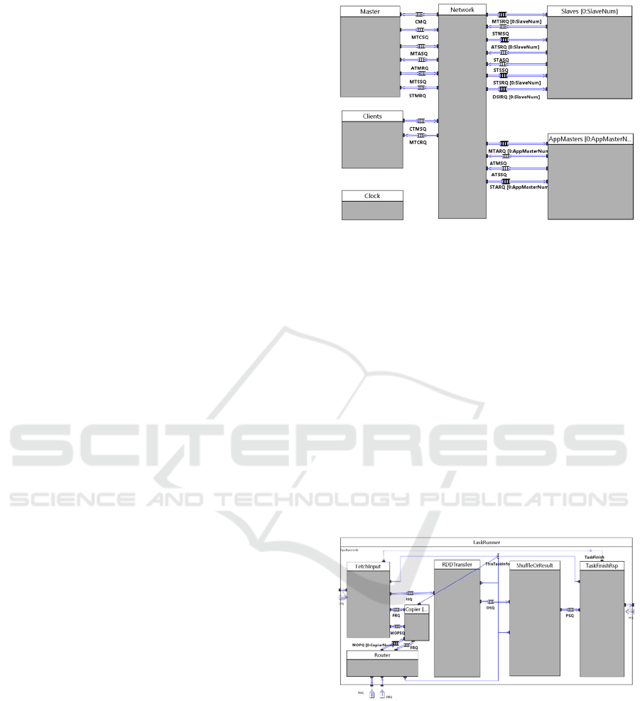
The top level of our Spark behaviour model is
shown in Figure 1, which includes: a Master, a
Network, Slaves, Clients and AppMasters.
Clients submit jobs to the cluster and act as
workload generators. The Master takes the resource
management role. The AppMaster analyses the job
configuration and generates a DAG of tasks to be
executed by slave nodes in the cluster. The Network
connects all the components logically and simulates
the Cluster network topology, bandwidth and latency.
The Clock model synchronizes the timing between all
the logic blocks. The Slaves receive tasks generated
by the AppMaster and launch the TaskRunner to
execute the tasks with resources provided by the
NodeResourceManager in themselves.
As shown in Figure 2 the TaskRunner simulates the
Spark task workflow behaviour, including:
fetchInput, RDD transfer, Shuffle and result
Figure 1: Top abstraction level of the Spark model.
computing. Different types of task inputs can be
fetched by the FetchInput module: HadoopRDD,
cached RDD, or shuffle RDD tasks. The remote
shuffle data are copied by the Copier and the Router
which are connected to the network module to
simulate shuffle behaviour. Fetched RDD blocks are
transformed by specific RDD operations in the
RDDTransform module. Depending on the specified
Spark task type, the transformed RDD block can be
used to form the result output or the shuffle output.
The result output is generated by the ResultTask
module which computes the final result and writes it
to HDFS. The shuffle output is generated by the
ShuffleMapTask module that partitions the output in
hash keys and then dispatches the output to specific
shuffle output files.
Figure 2: Middle abstraction level model of the Spark task
executor.
Finally the ‘task finish’ signal and the task
performance metrics are committed to the scheduler,
then the TaskRunner module waits for the next task
to be dispatched to it. Performance intensive software
functions like compress, decompress, serialize, de-
serialize, sort, hash operations are modeled within the
TaskRunner module.
Simulating Spark Cluster for Deployment Planning, Evaluation and Optimization
35
2.2 Memory Model
The RDD Block manager and the performance library
are used by the TaskRunner module to simulate
dataflow events (RDD block read/write, JVM/OS
memory apply/free, disk read/write, CPU apply/free,
network transfer, HDFS read/write) and to generate
the timing information. During the whole simulation
cycle the cluster hardware resource usage is tracked
and updated dynamically by the performance library.
Process Memory Manager
Virtual Address Paging & Swapping Manager
Physical Memory Manager
Physical Memory
Operating System
Global memory performance model Library
GC Manager
Java Object Manager
Java Heap Manager
Java Virtual Machine
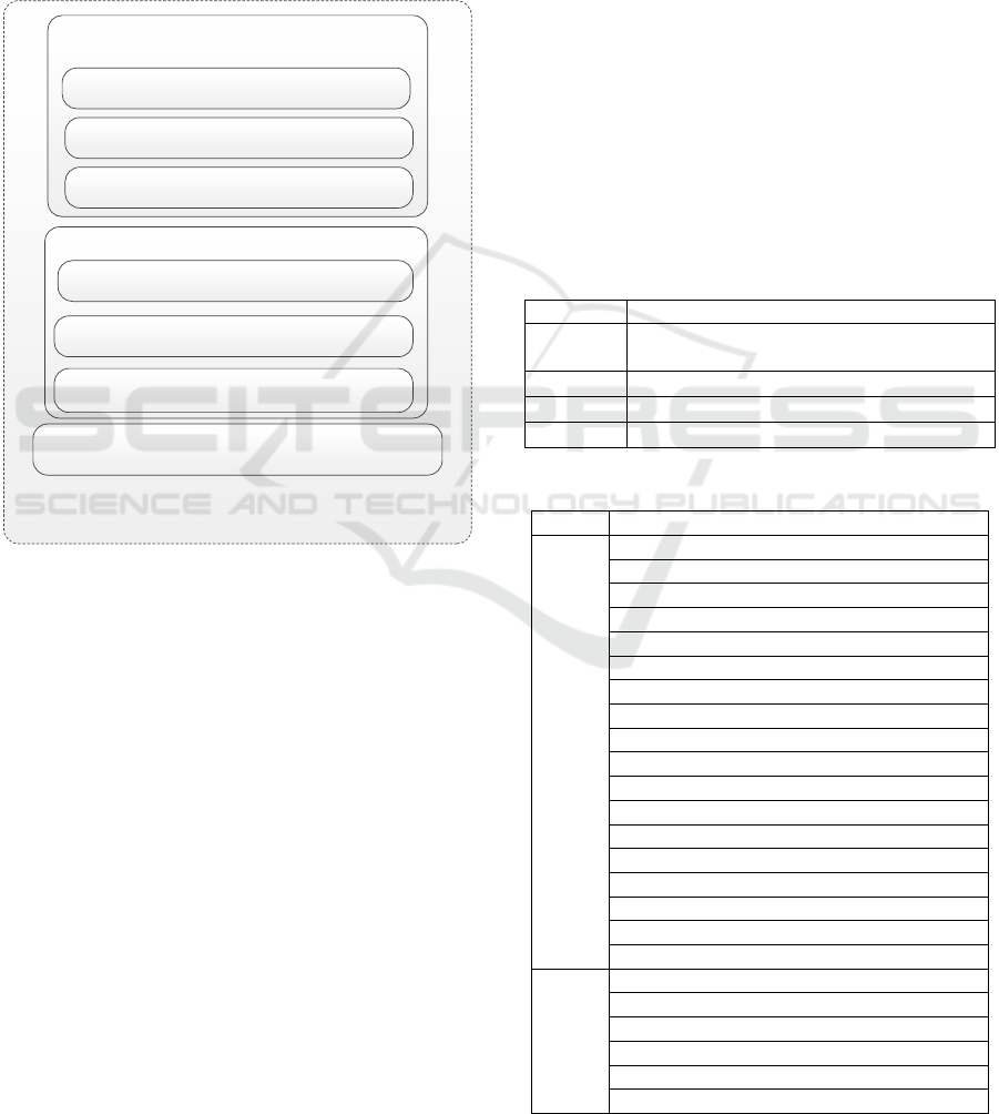
Figure 3: Structure of multiple layered memory model.
In order to obtain high accuracy, the Spark
simulation memory model has been implemented in 4
different layers: Spark, JVM, OS and physical
memory. The last three layers are modeled as a global
memory performance library as shown in figure 3,
and was called by the Spark layer to simulate RDD
block management behaviour.
• Spark software stack layer: Spark RDD block
management behaviour are modeled by simulating
RDD block put, get and cache operations.
• JVM layer: the JVM heap space capacity limits,
GC triggering mechanism and object management
behaviour are modeled, so that when JVM heap
doesn’t have enough free space to hold new object
then GC happens.
• OS layer: the virtual space, paging, swapping
slab and disk file cache/buffer behaviour are
modeled. The file (usually on disk) access requests
are cached or buffered by OS managed free system
memory.
• Physical memory layer: the physical memory
bandwidth latency and capacity limits are modeled by
keeping track of concurrent memory accesses.
The hierarchy of this memory model is similar to
real systems, each level is itself a class and has
respective behaviours and can be inherited. The
simulation granularity is configurable to achieve the
simulation trade-off between accuracy and speed, for
example swapping operation could be done per page
or per block.
This memory model simulates the full system
memory behaviour within a single process in a
standard personal computer with timely response.
2.3 Simulator User Input
The input of the simulator is composed of the Spark
S/W stack configuration, the H/W components
configuration and the Spark application/job
abstraction.
Table 1: Cluster hardware and software settings.
Cluster Node number and network topology
Processor Processor type, core count, thread count
and frequency
Storage Storage count and type: SSD or HDD
Memory Memory type and capacity
Network NIC count and bandwidth10 or 1 GBit/s
Table 2: Spark JVM OS parameters.
Level Modeled Software Parameters
Spark Spark.executor.memory
Spark.default.parallelism
Spark.storage.memoryFraction
Spark.shuffle.compress
Spark.shuffle.spill.compress
Spark.rdd.compress
Spark.io.compression.codec
Spark.io.compression.snappy.block.size
Spark.reducer.maxMbInFlight
Spark.shuffle.consolidateFiles
Spark.shuffle.file.buffer.kb
Spark.shuffle.spill
Spark.closure.serializer
Spark.kryo.referenceTracking
Spark.kryoserializer.buffer.mb
Spark.shuffle.memoryFraction
SchedulerReviveInterval
Akka threads number
YARN
Yarn.scheduler.minimum-allocation-mb
Yarn.scheduler.increment-allocation-mb
Yarn.scheduler.maximum-allocation-mb
Yarn.scheduler.minimum-allocation-vcores
Yarn.scheduler.increment-allocation-vcores
Yarn.scheduler.maximum-allocation-vcores
SIMULTECH 2016 - 6th International Conference on Simulation and Modeling Methodologies, Technologies and Applications
36
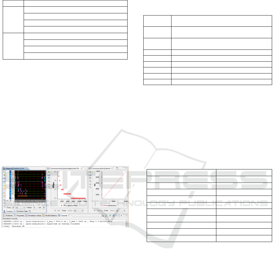
Table 2: Spark JVM OS parameters (cont.).
HDFS
Dfs.block.size
JVM
Heap size
Young generation ratio
EdenSurvRatio
GC drop ratio
OS
Memory flush ratio
Memory dirty ratio
Memory flush interval
Transparent huge page
The cluster hardware components configuration is
listed in Table 1. While the Spark software stack
configuration is listed in Table 2.
Model abstraction is defined from the following
aspects: RDD information: size, partition number,
and storage location (HDFS, shuffle and memory
cache). Operation information: operation type
(shuffle or map) and operation CPU cost.
2.4 Simulator Output
Timelines, charts and console output windows
provided by the Intel CoFluent Studio development
toolkit are used to visualize metrics.
Figure 4: Simulation result visualization.
The left part of Figure 4 shows the model
execution timeline which is useful to evaluate the task
execution order and timings. The middle and right
plots show system throughput and latency. Many
other metrics extracted from output result files are
also observed using spreadsheets.
3 EXPERIMENTAL SETUP
This section describes the configuration of our
experimental setup. It is followed by a presentation of
the benchmarks used for the evaluation of the model.
3.1 Experiment Cluster
Table 3: Cluster hardware and software settings.
Cluster 5 Nodes, connected by one rack switch
4 slave worker nodes 1 master node
Processor Intel® Xeon® E5-2697 v2, 24 cores per node
with HT disabled
Disk Direct Attached Storage, 5 x 600GB SSD per
node, 1 drive for OS, 4 drive for Spark S/W stack
Memory 128GB, 2 channel DDR3-1333 per node
Network 10 Gbit/s Ethernet
OS RedHat6.4
Java 1.7.0_67
Spark Spark 1.2
Platform CDH5.2
Table 3 lists the target cluster hardware components
and the software stack elements used for our baseline
experiments. This setup is representative of
mainstream datacenter configurations used for Big
Data processing.
3.2 Workload Description
Three workloads are used to conduct the experiments.
Table 4: Experimental workload baseline configurations.
K-Means parameters Value
Input Data set size in GB 40/80/160
Dimensions 30
Iteration number 5
Cluster number 1024
PageRank parameters
Input Data set size in GB 11/22/40
Iteration number 5
SparkTC parameters
Edges 200
Vertices 100/200/400
• K-Means:
Widely used in machine learning, K-Means clustering
is a method of vector quantization, popular for cluster
analysis in data mining. It aims at partition n
observations into k clusters in which each observation
belongs to the cluster with the nearest mean. As an
iterative application Spark K-Means is often used as
a typical application to show Spark advantage. The
configuration is shown in Table 4.
• PageRank:
PageRank is another good example of a more
complex algorithm with multiple stages of map and
reduce iterations. It benefits from Spark’s in-memory
caching mechanism with multiple iterations over the
same data. The algorithm iteratively updates a rank
for each document by adding up contributions from
Simulating Spark Cluster for Deployment Planning, Evaluation and Optimization
37
documents that link to it. The configuration is shown
in Table 4.
• SparkTC:
SparkTC is an implementation of transitive closure. It
can be thought of as establishing a data structure that
makes it possible to solve reachability questions (Can
I get to x from y?) efficiently. After the pre-
processing of the transitive closure construction, all
reachability queries are answered in constant time by
simply reporting a matrix entry (Skiena, 2008). The
configuration is shown in Table 4.
4 EVALUATION AND ANALYSIS
In addition to above micro-benchmark, we have also
validated our simulator with 2 machine learning
algorithms: SVM, ALS and an IoT real case usage
scenario, all with error rate less than 7%. As the
limitation of this paper, this section only describes the
micro-benchmark validation in detail.
The Spark simulator accepts 33 parameters for
each workload simulation, but we only choose several
parameters to do performance trend study, which are
related to the system performance bottleneck. Only
the most sensitive parameters are scaled while the
other parameters are set as default.
4.1 Baseline Validation
Three different workload input data sizes were used
to illustrate the accuracy of our simulator. The
detailed workload input parameters are shown in
Table 4.
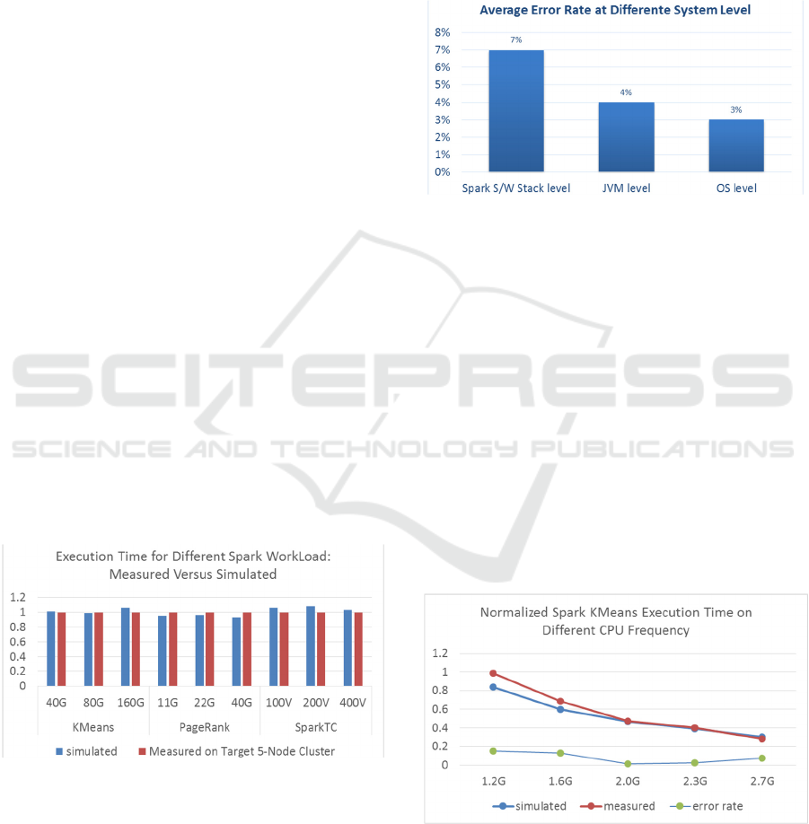
Figure 5: Measurement VS simulation of Spark
performance.
F
igure 5 shows normalized Spark execution times
as measured on the experimental cluster and as
predicted by the simulator. As we can see, the
simulation results are always very close to the real
hardware measurements, the average error rate is
4.5%.
4.2 Memory Model Accuracy Analysis
The simulation accuracy of memory related
parameter is evaluated at three different system
levels: Spark, JVM and OS.
Figure 6: Simulation accuracy of memory model.
As the model at higher system level are based on
the lower ones, the simulation accuracy of higher
level are lower than that of the lower one. As shown
in Figure 6, all average error rate are less than 7%.
4.3 Software and Hardware
Parameters Scalability Analysis
The scalability analysis has been extended to all
software and hardware parameters supported by the
framework which are list in table 1 and 2. It shows
that the average error rate between actual
performance and simulated performance is within 6%
regardless of the type of the software parameter being
changed. For hardware parameter scaling, the average
error rate is within 5%.
Figure 7: Normalized execution time of CPU Frequency
Scaling.
As software parameter scaling examples will be
descript in detail in section V, here we focus on a
SIMULTECH 2016 - 6th International Conference on Simulation and Modeling Methodologies, Technologies and Applications
38
processor scaling example to show the hardware
parameter scaling ability of our Spark model. The
computing intensive K-Means workload was selected
for this evaluation.
Figure 7 shows the CPU frequency scaling for the
K-Means workload. Higher CPU frequencies
improve the processing performance and reduce the
workload execution time. The simulated performance
has the same trend as the measured performance and
the average error rate is 7.7%.
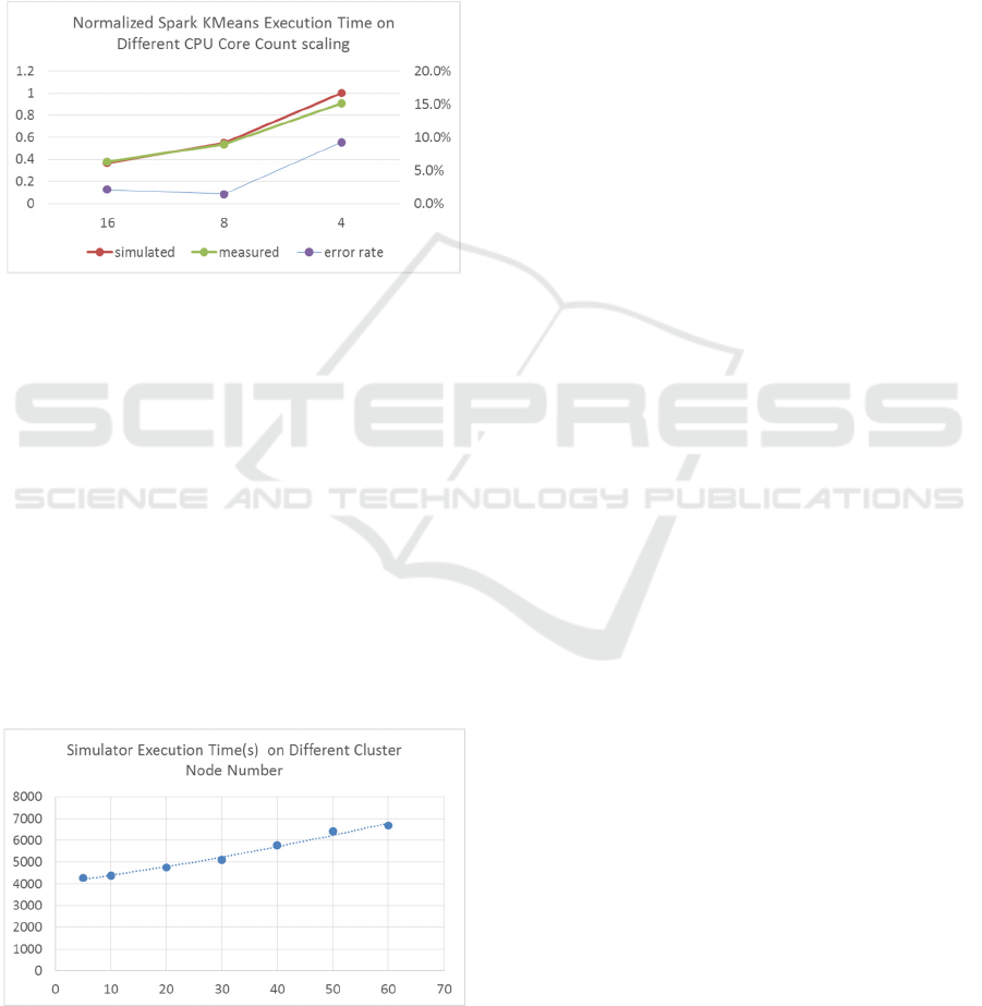
Figure 8: Normalized CPU Core Count Scaling.
Figure 8 shows the CPU core count scaling for the
K-Means workload. More CPU cores reduce the
workload execution time. Simulated and measured
performance have the same trend with an average
error rate of 4.2%.
4.4 Simulation Speed
All simulations are running on a standard desktop
equipped Intel(R) Core i7-5960 CPU and 16GB DDR
memory. For different benchmarks and
configurations, the native execution time on
experiment cluster ranges from 10 min ~ 30 min. To
predict the native execution time, the simulator would
cost 15 min to 4 hours.
Figure 9: Simulator execution time of 50GB dataset for
various node counts.
Figure 9 shows the actual simulation processing
time for a 50 GB data set processed by the Spark
PageRank workload. The cluster size is scaled from 5
to 60 nodes. The simulation processing time ranges
from 1 to 2 hours. This simulation speed is slower
than the lighting fast in memory computing engine:
Spark, but still acceptable for cluster deployment
planning evaluation and optimization.
5 CASE STUDY: MEMORY
TUNING FOR SPARK
PERFORMANCE
Memory tuning is critical in Spark. The Spark
PageRank optimization is a good candidate to
illustrate how memory settings at different layers
impact Spark performance, and how simulation based
tuning can help optimize Spark application
performance. Three configuration trade-offs at Spark,
JVM and OS levels are described in this section.
Spark PageRank is memory intensive and
generates a large set of intermediate data which
pushes up the system memory utilization. These
intermediate data are also shuffled across cluster
nodes. Shuffle is the operation that moves data point-
to-point across machines. It has a critical impact on
Spark performance, as shown in the latest Spark core
performance optimization work (Xin, 2015). In the
Spark workflow, intermediate data is held in the
memory buffer first and then written to disk when the
buffer is about to become full (buffer spilling). As the
latency of spill data write process is very long, the
size of the memory buffer reserved for intermediate
data heavily impacts the Spark performance.
5.1 Trade-off at Spark S/W Stack
Level
The spill buffer is part of the executor JVM heap,
whose size is controlled by the Spark parameter
shuffle.memory.fraction. If the spill buffer is large
enough to hold all the collected data, then no spill
occurs, or else, it flushes the buffer first and continue
to collect shuffle data.
Larger spill buffer size would reduce the number
of spill operations hence improving performance.
However since the spill buffer space is taken from the
JVM heap, a big spill buffer would leave very few
memory left for other tasks, such as RDD transfers,
that share the same JVM heap space.
Simulating Spark Cluster for Deployment Planning, Evaluation and Optimization
39
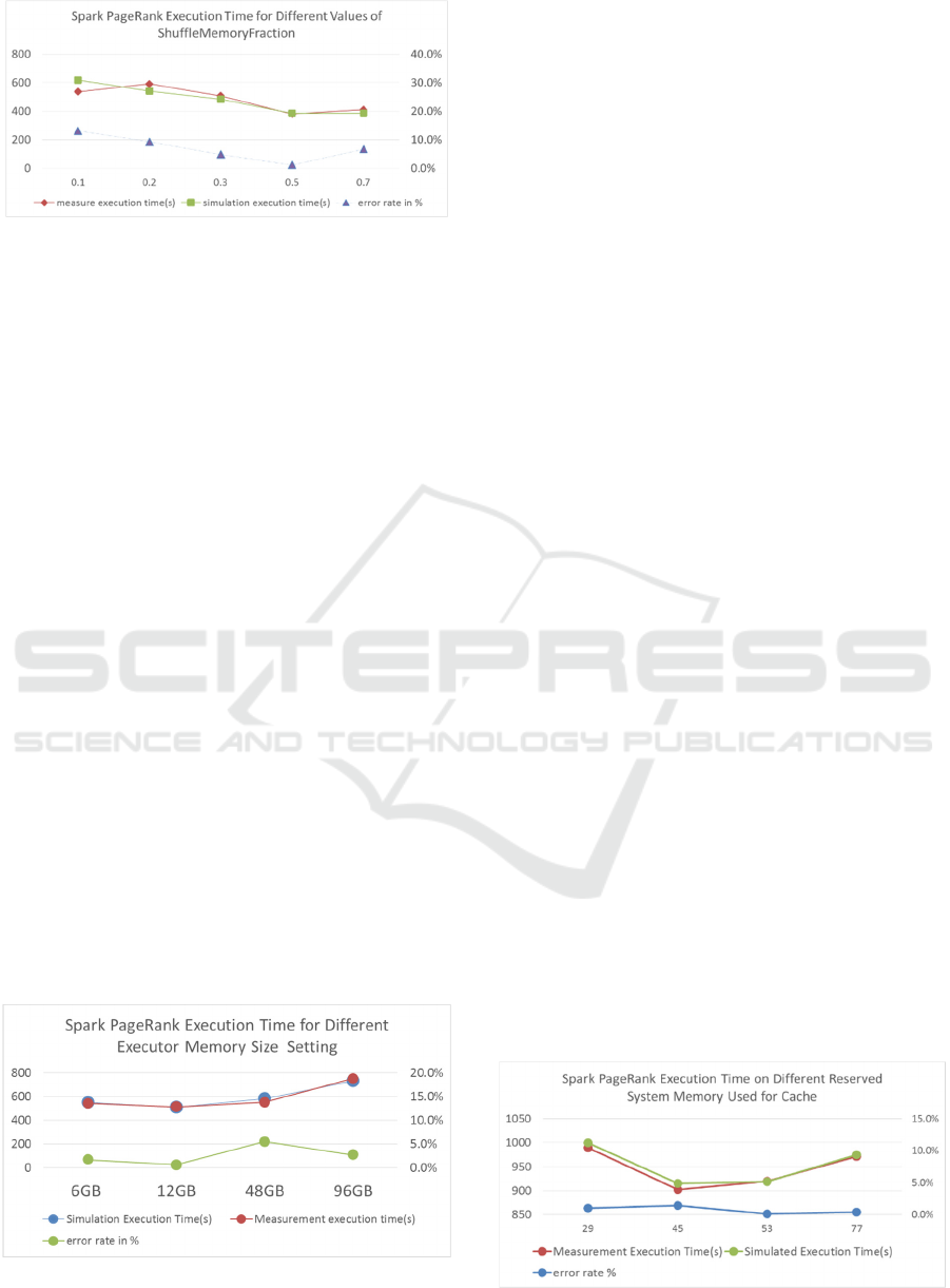
Figure 10: Spark shuffle buffer size scaling.
Figure 10 represents the Spark PageRank execution
time for different values of the
ShuffleMemoryFraction parameter. Best execution
time is achieved for 0.5. For values close to and less
than 0.5 scenario, better performance is achieved by
larger factor value since spill operations are the
bottleneck. However when above this threshold, too
much memory is consumed by the spill buffer, so
other tasks are delayed and overall spark performance
is pulled down. The accuracy of the simulated
execution time is mostly within 10% of the real
measured execution time.
Optimally setting the spill buffer size is an
example of difficult task that can be accurately solved
by simulation instead of less accurate experience
based decisions.
5.2 Trade-off at JVM Level
This study is to show executor memory trade off: A
big executor with more task slots or many small
executor memory with few slots. JVM and YARN
settings determine the executor memory
configuration and the number of tasks that runs in
parallel on this executor. We run the simulation with
three sets of different memory configurations:
1. 1 executor/96GB memory/16 task slots
2. 16 executor /6 GB memory/1 task slots
3. 4 executor /12 GB memory/2 task slots.
Figure 11: Spark executor memory scaling.
Figure 11 shows the executor memory scaling
results, in this case a 12GB executor memory would
be the best configuration. Simulation result also
paired with the measurement one to show our
simulation accuracy.
For the 1st approach, only 1 executor is created
with 96GB of memory and 16 task slots. The whole
JVM heap is shared by all the 16 tasks so as to
improve the utilization of the heap. For example if
one of the task have much less intermediate data
generated and cost less memory than the task in other
task slots, then the other task would use more
memory, so the whole executor memory utilization
would be improved. More memory utilization would
help reduce the spill operation and finally improve the
cluster performance. But on the other hand, as one
Spark executor utilize one JVM, 64GB memory for
one JVM would cause heavy overhead when GC,
which is another significant Spark performance
optimization challenge.
The 2nd approach is the opposite of the former
case: each executor has only one task slots with 6GB
of memory available.
The 3rd approach is a trade-off between
configuration 1 and 2, 4 executors are created each
with 8 GB memory and 2 task slots. This approach
achieves the best performance.
Generally speaking the impact of these factors on
performance is highly dependent on the actual
application type and the input data content. If GC
overhead is the bottleneck then the 2nd approach
achieves the best performance, while if the spill
overhead become the bottleneck the 1st approach
achieves the best performance. This makes Spark
cluster performance optimization a difficult
challenge.
5.3 Trade-off at OS Level
Figure 12 describes the final PageRank performance
changes with reserved OS memory scaling, when 48
GB of memory is reserved for file system
cache/buffer, best performance is achieved.
Figure 12: Reserved OS memory scaling.
SIMULTECH 2016 - 6th International Conference on Simulation and Modeling Methodologies, Technologies and Applications
40
At OS level, IO requests from Spark tasks are
cached/buffered by the OS when enough reserved
system memory is available causing significant
performance impact. For example, disk write requests
from Spark task’s spill operations are buffered by the
OS memory buffer since the corresponding disk IO
accesses can only happen when the disk drive write
buffer is full. While memory access bandwidth is
more than 10 times higher than that of disk access, OS
cache/buffer can bypass actual disk access through
memory access, that could improve spill operation
performance by more than 10 times. Linux would use
all free system memory as file cache/buffer to
generally benefit system performance. On this point,
larger reserved memory can benefit system
performance in the general case.
While at Spark cluster level, more memory
allocated to Spark tasks would increase execution
speed, but in turn reduce the reserved system
memory, potentially penalizing system tasks. This is
another system performance optimization trade-off.
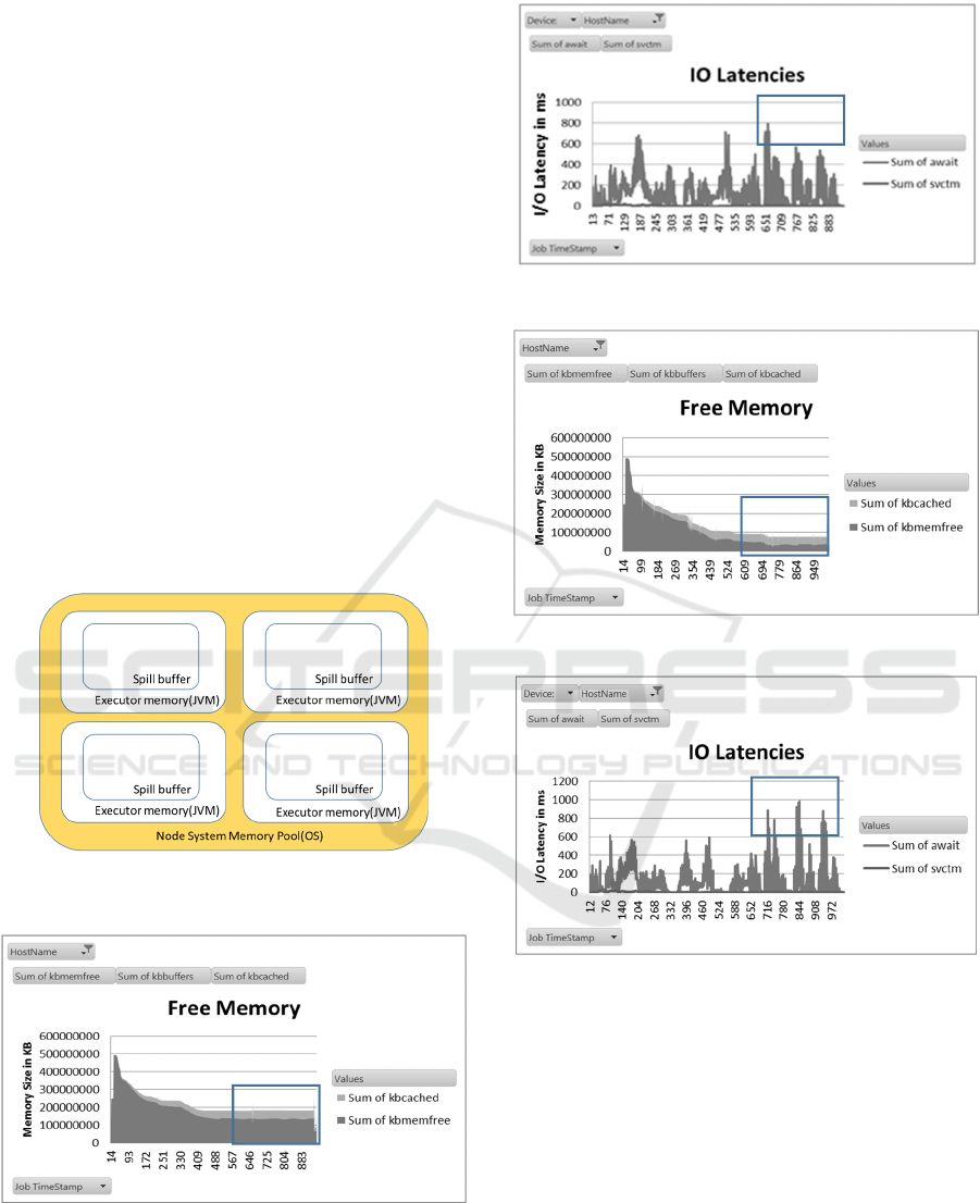
Simplified concept of hierarchical Spark cluster
memory is shown in Figure 13.
Figure 13: Simplified concept of OS memory JVM heap
and Spark spill buffer.
Figure 14: OS memory utilization for 45GB reserved
system memory case.
Figure 15: I/O latency for 45GB reserved memory case.
Figure 16: utilization for 29GB reserved memory case.
Figure 17: System I/O latency for 29GB reserved system
memory case.
The performance impact of the OS cache/buffer
can also be observed in experimental cluster hardware
measurement metrics. The Figure 14~17 show that
the disk I/O latency increases (could be found in
rectangle region) while the system free memory
decreases, which in turn can be used for additional
file caching/buffering. The Figure 14, 15 are memory
and I/O latency charts for 45GB of reserved OS
memory while the Figure 16, 17 are for 29GB. As
could be observed from these charts, for the 45GB
reserved memory case, I/O latency after time stamp
700 would less than 600 ms, which is smaller than
Simulating Spark Cluster for Deployment Planning, Evaluation and Optimization
41

that of 29 GB reserved memory (latency after time
stamp 700 would longer than 800 ms).
We presented three application specific trade-
offs. There is no general solution that can satisfy all
cases but simulation based optimization as
demonstrated in the following section can be used to
thoroughly explore the space of possible solutions so
that the best configuration trade-off can be found.
5.4 Simulation based Optimization
Figure 18 demonstrates how simulation based
optimization can be used in a systematic way to
explore execution time against the
shuffle.memory.fraction and the executor memory
size in GB. Best performance is achieved for a 12GB
executor memory size combined with a
shuffle.memory.fraction of 0.5. This represent a 71%
improvement compared to the default configuration
(6GB, 0.2). We can use the simulator to predict
performance for different cluster configuration
without real cluster deployment.
Figure 18: Simulation based optimization of Spark memory
system.
6 RELATED WORK
Several existing simulator are dedicated to simulate
the MapReduce computing paradigm, but no Spark
simulator is currently available. The most closely
related works are based on full system simulators
which usually are general purpose functional
simulators.
One of this kind is Simics-based (Magnusson et
al., 2002) cluster simulator that can run any kind of
unmodified Big Data applications and that can be
used to characterize Spark and other Big Data
workloads (BigDataBench, 2016). Simflex is based
on Flexus simulation engine and SMARTS rigorous
sampling engine (Simflex, 2016). Flexus was also
built on Simics, whose simulation speed is very slow
especially when the node number of the target cluster
increases. On the other hand Simcs can't provide
accurate timing information for cluster applications.
An instruction set simulator-based full system
simulator (Leon et al., 2009) can run unmodified
message-passing parallel applications on hundreds of
nodes at instruction level, but similarly because it is a
low level simulator its simulation performance is poor
and it can hardly be used for performance
optimization.
Compared to the above mentioned simulators this
paper proposes a fast and high accuracy layered
simulation framework. Several hundred nodes
clusters can even be simulated on a desktop in relative
short time.
7 CONCLUSION AND FUTURE
WORK
Planning, evaluating and optimization Big Data
clusters is very challenging due to vast hardware
diversity and rapidly increasing software complexity.
Experience or measurement based approaches are no
longer efficient.
As the computing core of next Big Data clusters,
Spark plays an important role in capacity planning
consideration. It is critical to be able to predict Spark
performance accurately and efficiently so that the
right design decisions can be taken. This is however
a challenging task due to the complex behaviour of
memory systems. In this paper, we proposed an
innovative simulator used to simulate Spark cluster
performance at system level.
We have validated its accuracy and efficiency via
several widely used micro-benchmarks.
Experimental results demonstrate the accuracy and
capability of our Spark simulator: the average error
rate is below 7% across the scaling of 33 software
parameters and 5 group of hardware settings.
The ability to quickly simulate Spark clusters with
high accuracy on commodity clients makes our
simulator a promising approach as a design tool to
perform capacity planning before real deployment.
For our 5 nodes 50 GB data set size configuration,
simulation times vary between 30 minutes and 4
hours.
Moreover system engineers could also use this
simulator to optimize Big Data cluster configuration,
maximize cluster performance, evaluate server design
trade-offs and make system-level design decisions.
For easier Spark development, the Spark
ecosystem brings additional functionality like MLib
(machine learning library), GraphX, Spark Streaming
SIMULTECH 2016 - 6th International Conference on Simulation and Modeling Methodologies, Technologies and Applications
42

and Spark SQL. We will extend our Spark model to
these functionalities.
REFERENCES
http://spark-summit.org/wp-content/uploads/2014/07/
Sparks-Role-in-the-Big-Data-Ecosystem-Matei-
Zaharia1.pdf.
https://spark.apache.org/
Zhaojuan Bian, Kebing Wang, Zhihong Wang, Gene
Munce, Illia Cremer, Wei Zhou, Qian Chen, Gen Xu,
2014. “Simulating big data clusters for system
planning, evaluation and optimization,” ICPP-2014,
September 9-12, 2014, Minneapolis, MN, USA.
Xin, Reynold; Rosen, Josh; Zaharia, Matei; Franklin,
Michael; Shenker, Scott; Stoica, Ion, 2013. "Shark:
SQL and Rich Analytics at Scale". SIGMOD.
Matei Zaharia, 2011. Spark: In-Memory Cluster Computing
for Iterative and Interactive Applications. Invited Talk
at NIPS 2011 Big Learning Workshop: Algorithms,
Systems, and Tools for Learning at Scale.
Matei Zaharia, Mosharaf Chowdhury, Michael J. Franklin,
Scott Shenker, Ion Stoica, 2010. “Spark: Cluster
Computing with Working Sets” HotCloud'10
Proceedings of the 2nd USENIX conference on Hot
topics in cloud computing pages 10-10, 2010, CA,
USA.
Apache Software Foundation, 27 February 2014. "The
Apache Software Foundation Announces Apache Spark
as a Top-Level Project". Retrieved 4 March 2014.
Wagner Kolberga, Pedro de B. Marcosa, Julio C.S. Anjosa,
Alexandre K.S. Miyazakia, Claudio R. Geyera, Luciana
B. Arantesb, 2013. “MRSG – a MapReduce simulator
over SimGrid,” Parallel Computing Volume 39 Issue
4-5, Pages 233-244, April, 2013.
Wang, G., Butt, A. R., Pandey, P., and Gupta, K., 2011. “A
simulation approach to evaluating design decisions in
MapReduce setups,” Proceedings of the 17th Annual
Meeting of the IEEE/ACM International Symposium on
Modelling, Analysis and Simulation of Computer and
Telecommunication Systems (MASCOTS '11), London,
UK, 2011.
Palson R Kennedy and T V Gopal, 2013. “A MR simulator
in facilitating cloud computing,” International Journal
of Computer Applications 72(5):43-49, June 2013.
Published by Foundation of Computer Science, New
York, USA.
A. Verma, L. Cherkasova, and R.H. Campbell, 2011. “Play
It Again, SimMR!”Proc. IEEE Int’l Conf. Cluster
Computing (Cluster ’11).
Intel,Simulation software http://www.intel.com/content/
www/ru/ru/cofluent/intel-cofluentstudio.html.
Steven S. Skiena, 2008. The algorithm design manual
Springer.
https://databricks.com/blog/2015/04/24/recent-
performance-improvements-in-apache-spark-sql-
python-dataframes-and-more.html.
P. S. Magnusson, M. Christensson, J. Eskilson, D.
Forsgren, G.Ha_llberg, J. Ho_gberg, F. Larsson, A.
Moestedt, and B. Werner, 2002. Simics: A full system
simulation platform. IEEE Computer, 35(2):50-58,
February 2002.
http://prof.ict.ac.cn/BigDataBench/simulatorversion/
http://parsa.epfl.ch/simflex/overview.html.
Edgar A. Leon, Rolf Riesen, Patric G. Bridges, Arthur B.
Maccabe, 2009. “Instruction-Level Simulation of a
Cluster at Scale” HPCC, Nov 14-20, 2009, Portland,
OR, USA.
Simulating Spark Cluster for Deployment Planning, Evaluation and Optimization
43
