
Engineering Real-Time Communication Through Time-triggered
Subsumption
Towards Flexibility with INCUS and LLFSMs
David Chen, Ren
´
e Hexel and Fawad Riasat Raja
School of Information and Communication Technology, Griffith University, Nathan QLD, Australia
Keywords:
Time-triggered Communication, Safety-critical Systems, Software Modelling, Subsumption Architecture,
Logic-Labelled Finite State Machines.
Abstract:
Engineering real-time communication protocols is a complex task, particularly in the safety-critical domain.
Current protocols exhibit a strong tradeoff between flexibility and the ability to detect and handle faults in a
deterministic way. Model-driven engineering promises a high level design of verifiable and directly runnable
implementations. Arrangements of logic-labelled finite-state machines (LLFSMs) allow the implementation
of complex system behaviours at a high level through a subsumption architecture with clear execution seman-
tics. Here, we show that the ability of LLFSMs to handle elaborate hierarchical module interactions can be
utilised towards the implementation of testable, safety-critical real-time communication protocols. We present
an efficient implementation and evaluation of INCUS, a time-triggered protocol for safety-critical real-time
communication that transcends the rigidity imposed by existing real-time communication systems through the
use of a high-level subsumption architecture.
1 INTRODUCTION
Nowadays, a model-driven software development ap-
proach is widely used by developers in contrast to
lower level implementation approaches, as it assists
in developing, faster and simpler modules and ap-
plications (Estivill-Castro and Hexel, 2013b). Fi-
nite State Machines (FSMs) or behaviour trees are
used to represent high level specifications of be-
haviours. This kind of modelling approach fulfills
the agenda of Model Driven Engineering (Schmidt,
2006) for software development. In contrast to other,
more traditional implementation approaches, Logic-
Labelled Finite-State Machines (LLFSMs) (Estivill-
Castro and Hexel, 2014) allow translating require-
ments into high-level, executable models (Billington
et al., 2011a). These are less susceptible to implemen-
tation errors as models can be directly interpreted,
simulated, verified, and executed on a large num-
ber of platforms, including embedded control sys-
tems (Estivill-Castro et al., 2012).
In control systems, where different modules are
interacting with each other, it becomes very impor-
tant to predict the results and shield the details of one
module from others. To solve this problem, the sub-
sumption architecture (Brooks et al., 1986) has pro-
posed behaviour based decomposition of such com-
plex systems into layers of increasing level of abstrac-
tion, where high level layers can subsume the lower
level layers. Several other similar approaches (Kael-
bling, 1987; Payton, 1986; Arkin, 1987) were de-
veloped but one big advantage of the subsumption
architecture is the ability to cater for the evolution
of the complexity of a control system by accretion
of higher-level layers. This approach allows the in-
cremental development of a control system, as addi-
tion of each new layer provides a new additional be-
haviour to the controller. Further layers can be added
on top of the existing layers without affecting their be-
haviours. This way, we can always have a functional
controller with each new behaviour throughout the de-
velopment process. So far, the subsumption architec-
ture has largely been used to build robotic control sys-
tems (Connell, 1987; Brooks et al., 1988; Mataric,
1990; Brooks, 1987).
In this paper, we use LLFSMs as a modelling tool,
where transitions from one state to another state are
based on expressions in logic rather than events. This
not only reduces the overhead significantly as, for ex-
ample, no memory allocations are required for event
queues, but also makes system performance more pre-
dictable. Although modelling with LLFSMs is a very
272
Chen, D., Hexel, R. and Raja, F.
Engineering Real-Time Communication Through Time-triggered Subsumption - Towards Flexibility with INCUS and LLFSMs.
In Proceedings of the 11th International Conference on Evaluation of Novel Software Approaches to Software Engineering (ENASE 2016), pages 272-281
ISBN: 978-989-758-189-2
Copyright
c
2016 by SCITEPRESS – Science and Technology Publications, Lda. All rights reserved

effective approach as shown in the literature (Billing-
ton et al., 2011b; Estivill-Castro and Hexel, 2013a),
to our knowlege, no attempts have been made to date
to use them towards the implementation of a safety-
critical, hard real-time system. We not only discuss
the implementation of INCUS (Chen et al., 2014) us-
ing LLFSMs, but we also show how the subsump-
tion architecture helps prevent design issues and how
an arrangement of LLFSMs has proven a better tech-
nique that enables to design and develop a more com-
plex protocol faster.
2 REAL-TIME
COMMUNICATION FOR
SAFETY-CRITICAL SYSTEMS
INCUS (Chen et al., 2014) is a communication proto-
col for distributed safety-critical real-time systems. A
real-time system distinguishes itself from other sys-
tems in that it is required to provide services within
defined time frames, which means it must meet cer-
tain deadlines. A deadline is the time limit by which
a task must be completed. Results delivered after
their deadlines lose some (in the case of soft dead-
lines) or all (in the case of firm deadlines) of their util-
ity. Safety-critical systems are systems where a fault
or missing a deadline can have severe consequences
such as injury or death, i.e., they are hard real-time
systems where missing a firm deadline can poten-
tially have catastrophic outcomes (Kopetz, 2011). To
prevent faults, safety-critical systems typically use
means of redundancy, such as replication and distri-
bution to tolerate or recover from these faults.
In distributed safety-critical real-time systems,
different nodes are connected with each other through
a shared communication channel such as bus. They
coordinate their actions through message passing,
therefore, timely and reliable message delivery is crit-
ical. Communication errors and unpredictable delays
in transmission may lead to unpredictable behaviour
of distributed real-time systems. For instance, con-
sider a brake-by-wire system in a car. When the driver
hits the brake pedal, then, based on physical parame-
ters such as the speed of the car and its wheels, a brake
force is calculated and transmitted to each wheel for
stopping the car. A slight delay or error in com-
munication may lead to a longer stopping distance
or even complete brake failure, potentially causing
harm. When nodes are sharing a single communica-
tion channel, generally one node at a time, is allowed
to transmit over this channel. Otherwise, simultane-
ous transmission by multiple nodes would interfere
with each other. This is known as a transmission col-
lision and all the nodes involved in the transmission
can lose their messages. Typical recovery techniques
such as positive acknowledgement and retransmission
(PAR) significantly differ in their performance be-
tween the best and the worst case and therefore ap-
proaches that do not impose different timing in the
case of faults (Lamport, 1984).
In light of these issues, the Time-Triggered Ar-
chitecture (TTA) (Scheidler et al., 1997; Kopetz and
Bauer, 2003) was introduced, which uses a Time Di-
vision Multiple Access (TDMA) scheme for chan-
nel access. Communication time slots used by the
nodes that make up the distributed system are de-
terministic and scheduled offline (Scheidler et al.,
1997). Therefore, all nodes know exactly at what
point of time each node will transmit its message
and this guarantees that channel access will be free
of collision. Well known communication protocols
for safety-critical real-time systems such as the Time-
Triggered Protocol (TTP) (Kopetz and Gr
¨
unsteidl,
1994) and FlexRay (Berwanger, 2001) use this ap-
proach for safety-critical real-time communication.
To this end, they use a scheme where nodes are al-
located static and equal length time slots to transmit
their information in each TDMA round of a cluster
cycle. However, this static scheme comes at the ex-
pense of flexibility. Unfortunately, in traditional ap-
proaches towards designing real-time communication
protocols, this tradeoff cannot be easily avoided and
so far, approaches that attempted to introduce a sig-
nificant amount of flexibility (Andersson et al., 2005;
Li et al., 2009) have failed to offer the same levels of
dependability or only offer flexibility for non-safety-
critical messages (Berwanger, 2001). We now show
how this tradeoff can be minimised in INCUS.
3 INCUS
Before discussing the implementation details of the
communication protocol using LLFSMs, we will
briefly discuss here the principles of operation of IN-
CUS.
1
INCUS is building on previous TTA proto-
cols (Kopetz and Gr
¨
unsteidl, 1994; Berwanger, 2001)
and is using a TDMA approach for channel access,
but unlike other TTA communication protocols, it
supports variable length node slots based on the trans-
mission payload of each node in each TDMA round
of a cluster cycle (Chen et al., 2014). In contrast
to protocols such as TTP and FlexRay, this offers
a higher degree of flexibility for each node to only
1
For reasons of space, the full specification of INCUS is
not replicated here, but can be found in Chen et al. (2014).
Engineering Real-Time Communication Through Time-triggered Subsumption - Towards Flexibility with INCUS and LLFSMs
273

transmit as much information as necessary, but in-
creases the complexity of the implementation. The
length of each message slot is configured in a data
structure called Message Descriptor List (MEDL).
To support deterministic communication, each IN-
CUS node has a replicated copy of the MEDL. The
MEDL not only stores the length of the individual
time slot, but also holds the time schedule for all
nodes, i.e., the exact time within the TDMA cycle
when a node can transmit and receive data to and from
other nodes is defined in advance. INCUS uses three
types of frames for communication, Normal frames
(N-frames), Initialisation frames (I-frames) and and
Coldstart frames (CS-frames). N-frames carry appli-
cation data, I-frames carry information for reintegra-
tion of lost/recovering nodes and CS-frames carry in-
formation for integration of all nodes during system
start-up.
As INCUS is designed to be used as a communi-
cation protocol for safety-critical real-time systems,
it provides fault tolerance mechanism in order to stay
operational in the presence of faults and maintain the
reliability and safety of the protocol (Chen et al.,
2014). A key criterion for fault tolerance, clique
avoidance, and the ability to form the basis of a fail-
operational system, the protocol uses a membership
service in following the principles of the TTA (Kopetz
and Bauer, 2003) to keep track of active and inac-
tive nodes after each TDMA round. Correspondingly,
each node stores its view of the fault-free operation of
other nodes (as perceived when receiving messages
from these nodes) in its membership vector. This
membership service also acts as an acknowledgement
scheme without the overhead of explicit membership
transmission during normal operation or the require-
ment for acknowledgments from receiver nodes. Im-
plicit transmission of the membership vector of each
node is done through frame CRC calculation, by in-
corporating the membership vector (and other vital
controller state information such as the current MEDL
position) in the CRC calculation of the sending and
receiving nodes, without actually transmitting this in-
formation. State agreement therefore is confirmed
through a CRC match, and nodes that have a different
point of view from the sender will detect a CRC error
and remove the sender from the membership vector.
Clique avoidance (Kopetz and Gr
¨
unsteidl, 1994) en-
sures that these minority nodes will no longer receive
frames from majority nodes until they restart and re-
integrate into the cluster again. Minority nodes are
able to detect that they are in the minority through a
membership vector that indicates that no more than
half the nodes are active. In other words, if fewer
than half of the nodes agree with a node, that node
knows that it no longer is part of a majority, causing
it to restart and re-integrate into the system based on
I-frames transmitted by other nodes.
Clock synchronisation is a core requirement of the
TTA and thus, INCUS uses a robust clock synchro-
nisation mechanism following the principles estab-
lished with TTP (TTTech, 2004). To maintain time,
all the nodes have physical clocks and a predefined
time schedule. Each node operating in the system
must synchronise its transmit or receive actions ac-
cording to the predefined time slots. This is only pos-
sible if the nodes’ clocks are synchronised. A differ-
ence between the expected arrival time (defined in the
MEDL) and the actual arrival time of a frame at re-
ceiver node is measured and then used to compensate
for the clock skew between the clocks of sender and
receiver nodes. The Fault Tolerant Average (FTA) al-
gorithm (Kopetz and Ochsenreiter, 1987) is then used
to correct the clock of each node based on the mea-
sured deviations.
4 EXECUTABLE
COMMUNICATION MODEL
When implementing a communication protocol, a key
design decision is the choice of tools and the level
of modelling for this implementation. The prototype
software for TTP/C, for example, was designed at a
low, procedural level and implemented using a mix
of C++ and assembly language (Kopetz et al., 1997).
While this approach certainly offers predictable, high
performance (short only, perhaps, of a direct hard-
ware implementation), a key disadvantage is the de-
sign and development effort (several man years) re-
quired by such an approach. Moreover, low-level
software is often wedded to a specific hardware and
difficult to port to a different platform. Neverthe-
less, to date, the rigorous timing requirements that
need to be modelled early on in the design process
has made it difficult to model verifiable executable
real-time behaviour at a high level (Estivill-Castro
and Hexel, 2015). These and other difficulties of-
ten encountered with high level engineering of soft-
ware has often prompted the question of whether it
makes sense to engineer software, and hence, there
is now a trend to view engineering as craft supported
by theory, leading to best practices in software en-
gineering (Jacobson and Seidewitz, 2014). A com-
mon element in software architectures in general, but
particularly in control software, are finite-state ma-
chines. In fact, the most commonly used artefact
for the description of software behaviour in UML
are state diagrams (Erickson and Siau, 2007; Reg-
ENASE 2016 - 11th International Conference on Evaluation of Novel Software Approaches to Software Engineering
274
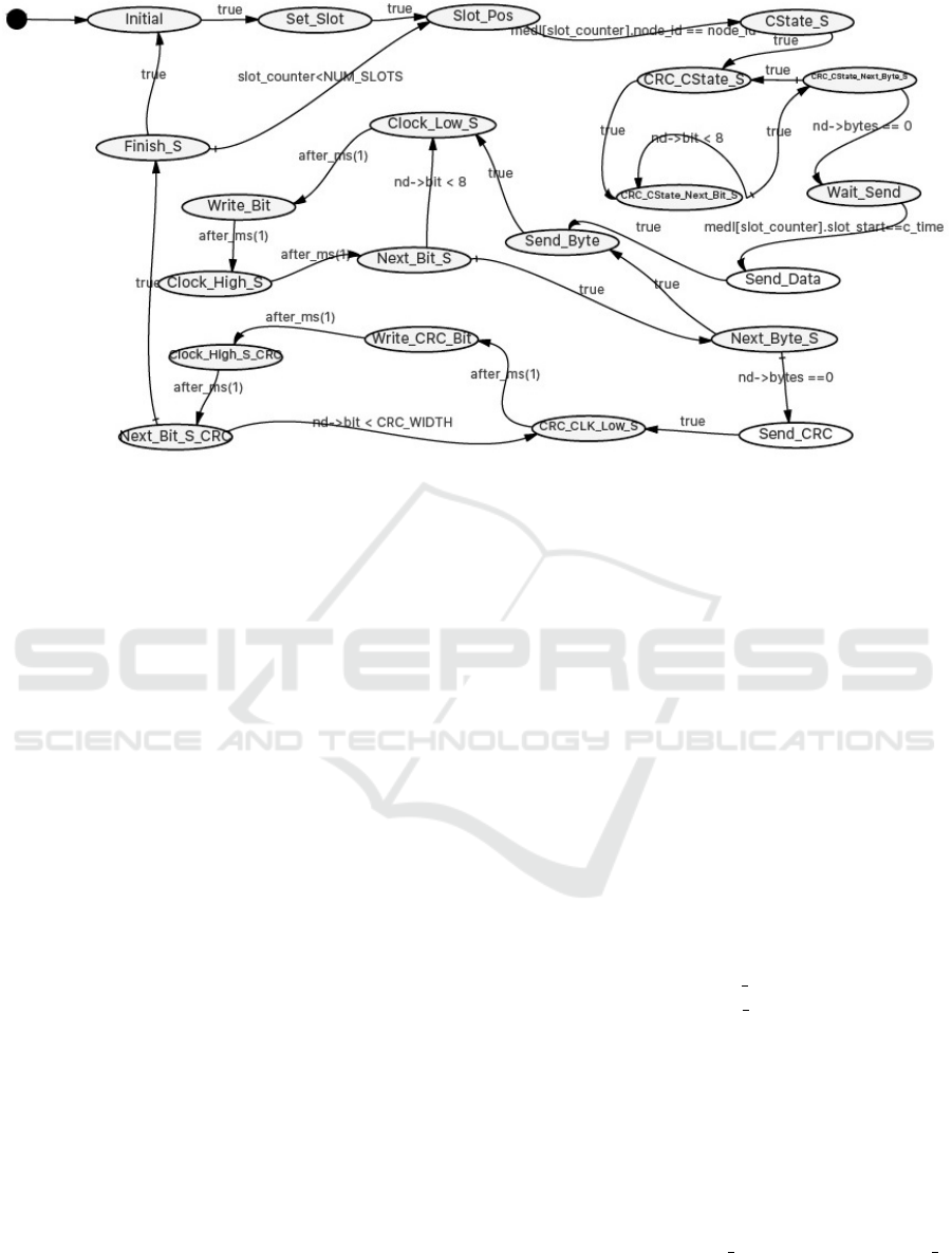
Figure 1: Transmission behaviour of INCUS using an individual LLFSM.
gio et al., 2013). Logic-labelled finite-state machines
(LLFSMs) are turing complete, making them funda-
mentally equivalent to any mechanism to model sys-
tem behaviour, with key advantages (Estivill-Castro
and Hexel, 2015) that shall make them the preferred
model here. First, they offer a very clear semantics of
concurrency, tremendously simplifying the cognitive
burden for the developer (Estivill-Castro and Hexel,
2015). Importantly, though, their execution seman-
tics much more closely resembles the principles of the
TTA (Kopetz and Bauer, 2003) and is in direct con-
trast with the optimistic best-effort approach of event-
driven systems (Estivill-Castro and Hexel, 2015). We
implemented INCUS through executable models us-
ing LLFSMs, and to our knowledge, this is the first
attempt at implementing software suitable for safety-
critical hard real-time systems using this approach.
4.1 LLFSM Design of INCUS
In our first iteration, we embedded all the lower level
and higher level implementation details in a single
LLFSM. To this end, we modelled INCUS in stages,
starting from the very basic functionality of the pro-
tocol, i.e., transmit and receive message at a pre-
defined point of time, following the time-triggered
approach (Chen et al., 2014) of the specification.
Then, we added the basic fault tolerance algorithms
and mechanisms (FTAMs), e.g. the Cyclic Redun-
dancy Check (CRC) whether a received message is
corrupted. Step by step, we incrementally added ad-
ditional behaviours required by the protocol to take it
towards the full specification. Each of the steps was
designed using MiCASE (Estivill-Castro et al., 2014)
and compiled to an executable that was run, tested,
and verified using clfsm (Estivill-Castro et al., 2014).
What is important to note is that, since LLFSMs rep-
resent executable models, each of these steps, despite
not yet implementing the full specification, gave us a
fully functioning, executable prototype that we were
able to simulate, exectute, test, and validate.
The complete INCUS specification is described in
Chen et al. (2014) but here, we will focus on one
key aspect and briefly discuss the implementation of
the transmission behaviour of INCUS using a single
LLFSM as shown in Figure 1. In the Initial state,
all the necessary parameters are initialised such as
the Message Descriptor List (MEDL) that holds the
time schedule for the data transmission and recep-
tion phase for all nodes. Each node has an identical
copy of the MEDL. All nodes starts from slot zero
as their first slot in the Set Slot state, then transi-
tioning straight to the Slot Pos state. In this slot,
each node will check the MEDL to figure out whether
it needs to act as a sender node or receiver node ac-
cording to the current slot position. Note that, since
we are discussing the message transmission mecha-
nism of INCUS, we are ignoring the receiver part (as
a receiver node) of INCUS in this example, but the
receiver follows analog steps to the transmitter states
discussed below. So if in the current slot, the node is
meant to act as a sender node, a corresponding transi-
tion is made from the Slot
Pos state to the CState S
state. The Controller State (C-State) is initialised in
this state so that CRC value can be calculated over
the C-State. This allows a message to be rejected as
Engineering Real-Time Communication Through Time-triggered Subsumption - Towards Flexibility with INCUS and LLFSMs
275

incorrect, not only if there is a physical transmission
error, but also if there is any other fault that causes
C-State disagreement (Kopetz et al., 1997).
After initialisation of the C-State, the node tran-
sitions to the next state CRC CState S. From there,
it takes a byte at a time and calculates the CRC
on each individual bit of that byte and when fin-
ished, takes the next byte. This continues until there
are no more data left for transmission. This whole
procedure is achieved through the state transitions
from the CRC CState S, CRC CState Next Bit S,
and CRC CState Next Byte S states. The next state
after CRC calculation is the Wait Send state, from
which a transition is made to the Send Data state,
only once the time at sender node is equal to the time
defined in the MEDL for the actual message trans-
mission. This time is termed the slot start time and
implements the essential time trigger for the sender
node.
It is important to note that, other than the con-
ditional transitions shown in the figure, there is no
conditional code here, making, together with the de-
terministic scheduling of clfsm (Estivill-Castro and
Hexel, 2015), the execution time of the compiled
code extremely predictable in correspondence with
the structure of the high-level model. In fact, the
worst-case execution time (WCET) is essentially the
same as the best-case execution time, minimising the
temporal jitter of the transmission start state. In this
state, the Send Data state, the original message and
number of bytes of the message are fetched from the
MEDL and then the next state is the Send Byte state.
This state takes one byte of the message at a time,
and transmits it bit by bit (through the Clock Low S,
Write Bit, and Clock High S states, also updating
the CRC at each step), and then looks for the next
byte (Next Byte S).
Once no bytes are left to transmit (nd->bytes ==
0), the sender transitions to the Send CRC state, where
all the bytes of the CRC are transmitted. The mecha-
nism of CRC transmission is same as the transmission
of the original message and the states used for trans-
mitting CRC value (CRC CLK Low S, Write CRC Bit,
Clock High S CRC, and Next Bit S CRC), have anal-
ogous functionality to the data transmission states
above, but transmit the CRC instead. The Finish S
state concludes the cycle, incrementing the MEDL
slot position and transitioning straight back to
Slot Pos if there are more MEDLs slots to operate
on, or back to Initial, if the end of the TDMA cy-
cle has been reached and the above steps repeat from
the beginning of the MEDL (slot zero).
One pattern that becomes apparent in this initial
design is a replication of concerns. In other words,
despite the fact that the above description only de-
tails the transmission phase of the protocol, we al-
ready have replicated the relevant states used in mes-
sage transmission, i.e., the states required for trans-
mitting the CRC essentially mirror the states used for
transmitting the message payload. The states repre-
senting the receiver very much mirror the sequence
described above, with only minor differences, such
as the provision of a small receive window to com-
pensate for clock drift and jitter. Up to this point,
the complete LLFSM, including the receiver, already
contains fifty states and we have not yet implemented
important parts of the communication protocol spec-
ification, such as the behaviour for the node start-up
and reintegration, clock synchronisation, the member-
ship service, mode changes, and other FTAMs such
as the detection of transmit and receive errors on the
basis of different timeout parameters. As this single
LLFSM grows bigger, it becomes more complex and
was nearly impossible to add remaining behaviours of
the protocol by adding and replicating more states.
Nevertheless, this initial implementation already
serves as a very important proof that it is not only
possible to implement a protocol for safety-critical
real-time systems using LLFSMs, but also that it
can be done much more rapidly (several weeks vs.
a few man-years) at a high level, yet yielding fully
executable models at every stage. This leads us to
the next stage of considering a refined approach that
greatly enhances the modularity of the design.
5 INCUS SUBSUMPTION
To reduce the complexity of the overall design and
increase the modularity, we follow the principles of
the subsumption architecture (Brooks et al., 1986),
allowing us to split out functionality into modules
that can hierarchically be subsumed by higher level
modules. Arrangements of LLFSMs allow the imple-
mentation of a subsumption architecture by integrat-
ing a number of different finite-state machines, each
forming a component or module that can be deacti-
vated using a suspend operation or activated using
a resume or restart operation
2
(Estivill-Castro and
Hexel, 2013a).
State machine vectors formed by an arrange-
ment of LLFSMs make the decomposition of sub-
behaviours into modules particularly straightforward.
We already identified repetitive the sub-behaviours,
such as the transmission of CRC vs. payload data, and
2
With LLFSMs, the restart operation simply restarts
the machine from its Initial state, while the resume op-
eration resumes from the previously active state.
ENASE 2016 - 11th International Conference on Evaluation of Novel Software Approaches to Software Engineering
276
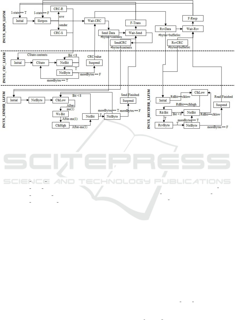
Figure 2: The Subsumption Architecture of INCUS.
splitting these elements out into individual modules
is as simple as factoring out those states into an indi-
vidual sub-machine. A decomposition of our earlier,
single LLFSM implementation of INCUS into the fol-
lowing four sub-LLFSMs is shown in Figure 2:
1. INCUS MAIN LLFSM
2. INCUS CRC LLFSM
3. INCUS SENDER LLFSM
4. INCUS RECEIVER LLFSM
The INCUS-MAIN-LLFSM module acts as a high-
level master-LLFSM that actually controls the be-
haviour of the other sub-LLFSMs. These sub-
machines are composed of the CRC-LLFSM,
SENDER-LLFSM, and RECEIVER-LLFSM ma-
chines. The Main LLFSM runs concurrently with
the sub-LLFSMs and only has the principle purpose
of implementing the high-level stages of the protocol
and to suspend and restart the sub-machines. These
sub-machines are the modules in the subsumption ar-
chitecture that implement the corresponding underly-
ing behaviours, when required.
In the previous section 4.1, we took the exam-
ple of message transmission in INCUS using a sin-
gle LLFSM to highlight the issue of design complex-
ity. In the following section, we will demonstrate how
we tackle this complexity issue by implementing the
message transmission behaviour of INCUS using the
subsumption architecture.
5.1 Tackling Design Complexity using
Subsumption
The implementation of the transmission behaviour of
INCUS using the subsumption architecture is done
by decomposing the single LLFSM from Figure 1
into the three sub-LLFSMs 1–4, i.e., INCUS MAIN-
LLFSM, INCUS CRC-LLFSM, INCUS SENDER-
LLFSM, and INCUS RECEIVER-LLFSM. Figure 3
shows the main machine. The main machine acts
as a master LLFSM and can run concurrently with
the sub-LLFSMs. While the subsumption architec-
ture allows multiple sub-machines to operate concur-
rently, and while the execution semantics of LLF-
SMs is clearly defined to avoid concurrency issues or
temporal inconsistencies (Estivill-Castro and Hexel,
2015), we deliberately kept the design of the INCUS
implementation simple, not requiring the concurrent
operation of multiple sub-machines at the same time.
This greatly simplifies WCET measurement and fur-
ther reduces the design and validation complexity of
the system.
The overall transmission mechanism follows the
steps discussed in Section 4.1. After initialising
the relevant protocol parameters in its Initial state
and verifying, in the Chk Slot Pos state, whether
the current node is the sender node. If the node
is the current transmitter, it transitions to the new
state CRC CState S. To perform the CRC calcula-
tions over the local C-State prefixing the payload
Engineering Real-Time Communication Through Time-triggered Subsumption - Towards Flexibility with INCUS and LLFSMs
277
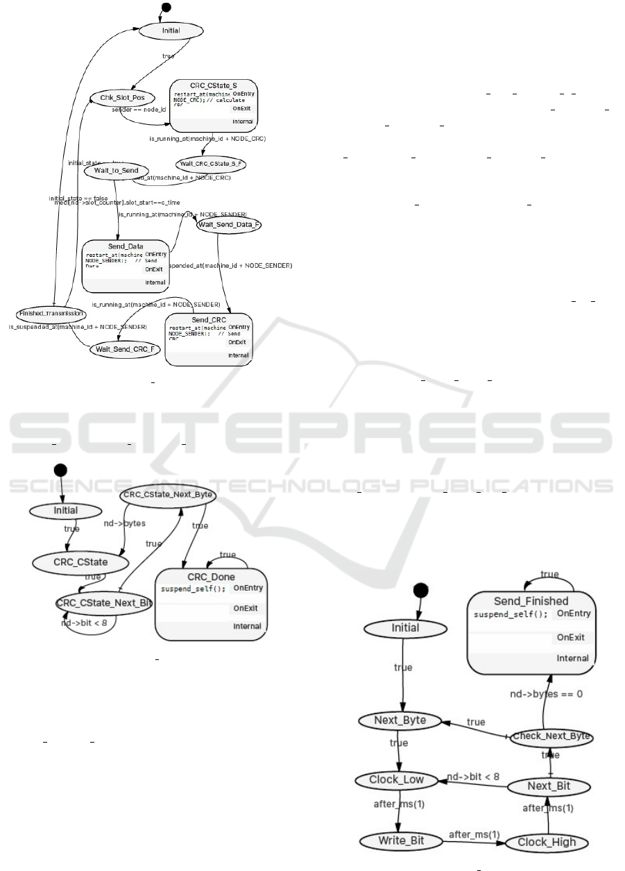
Figure 3: INCUS MAIN LLFSM.
transmitted in the message, the main LLFSM will
now activate the CRC module (Figure 4) by using
restart at(machine id+NODE CRC).
Figure 4: INCUS CRC LLFSM.
The CRC LLFSM runs concurrently with the main
machine and performs the CRC calculation over the
data referenced by the main LLFSM. In the case of
the CRC CState S state of the main machine, the CRC
data reference points to the C-State that the CRC shall
be calculated over. The states of the CRC LLFSM
are same the ones described in Section 4.1, but the
clear advantage here is that we do not need to replicate
these states multiple times, whenever we are required
to perform a CRC calculation. In fact, this calculation
is irrespective of the node’s current role as a sender or
receiver, and thus, unlike in the previous implementa-
tion, no further replication is necessary.
While the main machine technically runs
concurrently with the CRC module, activating
the CRC module does not require any con-
current operation, so the main LLFSM simply
transitions to the Wait CRC CState S F state
(through the transition labelled is running at
(machine id+NODE CRC)) where it waits for
sub-machine completion through use of the
is suspended at(machine id+NODE CRC) predi-
cate. To notify completion through this predicate,
the CRC LLFSM will simply suspend itself by
using suspend self() in its CRC Done state after
having completed calculating the CRC value. This
is semantically equivalent to subsumption akin to
the UML sub-machine notation (Estivill-Castro and
Hexel, 2013a).
As soon as the CRC calculation has concluded,
the main machine transitions to the Wait to Send
state, where it waits for the arrival of the transmission
slot action time. To transmit the message, the main
LLFSM now activates the sender LLFSM (Figure 5),
while again simply waiting for completion by sitting
idle in the Wait Send Data F state until the sender
LLFSM has completed and suspended itself. Unlike
the example from Section 4.1, where the transmission
logic had to be replicated for transmitting the mes-
sage CRC, the same sender LLFSM can now be used
and will be restarted by the main machine when in
order to send the CRC value as implemented by the
Send CRC and Wait Send CRC F states in the main
LLFSM. So contrary to the implementation of trans-
mission behaviour using the single LLFSM, the sub-
sumption architecture eliminates the complexity im-
posed by state-replication, while maintaining the abil-
Figure 5: INCUS Sender LLFSM.
ENASE 2016 - 11th International Conference on Evaluation of Novel Software Approaches to Software Engineering
278

ity to implement real-time behaviour following the
same, conceptual design principles.
5.2 Adding New Behaviours using the
Subsumption Architecture
We will now briefly describe the subsequent, iterative
steps that were conducted using the subsumption ap-
proach. It would have been hard to continue the mod-
elling of INCUS using a single LLFSM due to the
complexity explosion alluded to earlier. In the fol-
lowing analysis we will show how straightforward it
now is to add a new behaviour while retaining all the
functionality of the existing behaviours of INCUS us-
ing the subsumption architecture and arrangements of
LLFSMs.
5.2.1 Start-up and Re-integration of Nodes
So far, we assumed in our implementation that all
nodes successfully resolved their start-up collision
scenario (TTTech, 2004) and they are in the state
where they have synchronised clocks and ready to
transmit/receive messages. To implement system
startup and reintegration in accordance with the IN-
CUS specification (Chen et al., 2014), we need to add
add another sub-LLFSM as shown in Figure 6. We
named this machine RE INTEGRATION LLFSM in
a sense that this LLFSM is, in the fault-free case,
used only once to run the start-up scenario when all
the nodes are turned-on initially. After this, the main
LLFSM is used most of the time, but has the abil-
ity to trigger a restart to re-integrate a lost node to
the cluster of nodes in case of a fault that requires
re-integration. The re-integration LLFSM acts as a
master-LLFSM only when all nodes are turned-on the
first time. It will suspend all other sub-LLFSMs and
runs the node start-up algorithm. Once all the nodes
are up, the RE INTEGRATION-LLFSM will suspend
itself after starting the main LLFSM. Now the sphere
of control shifts to the main machine as above, which
will perform the normal operation of the protocol as
described. Importantly, a comparison between Fig-
ure 2 and Figure 6 shows that addition of this new be-
haviour has been achieved by just adding a single new
layer on top of INCUS MAIN LLFSM. Most impor-
tantly, the main machine did not require any modi-
fication or change to the structure of the previously
existing layers of LLFSMs.
6 CONCLUSION AND FUTURE
WORK
In summary, we have shown that a high-level imple-
mentation of a communication protocol for safety-
critical real-time systems based on the subsumption
architecture is not only possible, but facilitates the
incremental development of the system using exe-
cutable models throughout. We have shown that with
an INCUS implementation based on the arrangement
of LLFSMs, the scope of the subsumption architec-
ture is not limited to modelling the behaviours of tra-
ditional control systems, but we can also use it to de-
velop finite-state machines with predictable execution
semantics and timing. We have demonstrated that
LLFSMs support system development of INCUS in
an iterative way or in stages, where we can execute,
test and refine a safety-critical real-time system at a
given level before starting a new level. This allowed
us to ultimately implement a more flexible commu-
nication protocol in comparison with existing TTA
based communication protocols, where the imple-
mentation, refinement, and validation was a lot more
complex. Our modelling technique has been shown to
make feasible designing flexibility into communica-
tion protocols with the strict predictability and timing
required by dependable real-time systems. Further-
more, we have shown that the complexity of state-
replication can be avoided very effectively by using
the subsumption architecture provided by arrange-
ments of LLFSMs when developing a communication
system, without losing the fundamental properties of
predictable real-time performance. The subsumption
architecture made it possible to incrementally refine
our implementation by adding, modifying, or chang-
ing the behaviour of a sub-system without interfering
with unaffected components of the system.
So far, we modelled and implemented a safety-
critical cluster of INCUS using LLFSMs. In future,
we are aiming to design a more flexible and rather
more complex model of INCUS where more than one
safety-critical clusters will be linked through a net-
work that also carries a non real-time traffic. We ex-
pect that this will allow us, for example, to connect
safety-critical sub-systems over the internet or other
unreliable networks. We intend to adopt the same
modelling approach discusses in this paper and we
will evaluate the effectiveness of this approach i.e.
subsumption through LLFSMs for designing this hy-
brid and more complex real-time communication. In
this case, the mechanisms of the protocol regarding
timing requirements and fault-tolerance for safety-
critical traffic will be highly complex, but based on
the results presented here, we expect this approach to
Engineering Real-Time Communication Through Time-triggered Subsumption - Towards Flexibility with INCUS and LLFSMs
279
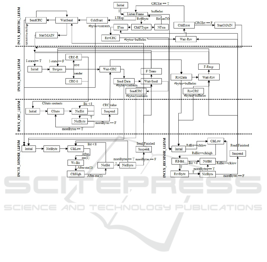
Figure 6: Addition of new behaviour using Subsumption Architecture.
demonstrate that even highly-complex systems can be
implemented using our technique while maintaining
system dependability.
REFERENCES
Andersson, B., Tovar, E., and Pereira, N. (2005). Analysing
TDMA with slot skipping. In Proc. 26th IEEE Inter-
national Real-Time Systems Symposium (RTSS).
Arkin, R. C. (1987). Motor schema based navigation for a
mobile robot: An approach to programming by behav-
ior. In Robotics and Automation. Proceedings. 1987
IEEE International Conference on, volume 4, pages
264–271.
Berwanger (2001). et al. FlexRay the communication sys-
tem for advanced automotive control systems. SAE
Transactions, Vol. 110(7):SAE Press, pp. 303–314.
Billington, D., Estivill-Castro, V., Hexel, R., and Rock,
A. (2011a). Requirements engineering via non-
monotonic logics and state diagrams. In Evaluation of
Novel Approaches to Software Engineering (ENASE
selected papers), volume 230 of Communications in
Computer and Information Science, pages 121–135,
Athens, Greece. Springer Verlag.
Billington, D., Estivill-Castro, V., Hexel, R., and Rock,
A. (2011b). Requirements engineering via non-
monotonic logics and state diagrams. In Evaluation
of Novel Approaches to Software Engineering, pages
121–135. Springer.
Brooks, R. et al. (1986). A robust layered control system
for a mobile robot. IEEE Journal of Robotics and Au-
tomation, 2(1):14–23.
Brooks, R. A. (1987). Micro-brains for micro-brawn: Au-
tonomous microbots. In IEEE Micro Robots and Tele-
operators Workshop: An investigation of microme-
chanical structures, actuators and sensors, Hyannis,
MA.
Brooks, R. A., Connell, J., and Ning, P. (1988). Herbert: A
second generation mobile robot. MIT AI Memo 1016.
Chen, D., Hexel, R., and Raja, F. R. (2014). INCUS: A
communication protocol for safety-critical distributed
real-time systems. In proceedings of 20th Asia-
Pacific Conference on Communications (APCC), Pat-
taya, Thailand.
Connell, J. (1987). Creature design with the subsumption
architecture. In IJCAI, volume 87, pages 1124–1126.
Erickson, J. and Siau, K. (2007). Can UML be simplified?
practitioner use of UML in separate domains. In pro-
ceedings EMMSAD, volume 7, pages 87–96.
Estivill-Castro, V. and Hexel, R. (2013a). Arrangements
of finite-state machines semantics, simulation, and
model checking. In Hammoudi, S., Ferreira Pires, L.,
Filipe, J., and C
´
esar das Neves, R., editors, Interna-
tional Conference on Model-Driven Engineering and
Software Development MODELSWARD, pages 182–
ENASE 2016 - 11th International Conference on Evaluation of Novel Software Approaches to Software Engineering
280

189, Barcelona, Spain. SCITEPRESS Science and
Technology Publications.
Estivill-Castro, V. and Hexel, R. (2013b). Module isola-
tion for efficient model checking and its application
to FMEA in model-driven engineering. In ENASE
8th International Conference on Evaluation of Novel
Approaches to Software Engineering, pages 218–225,
Angers Loire Valley, France. INSTCC.
Estivill-Castro, V. and Hexel, R. (2014). Correctness by
construction with logic-labeled finite-state machines
– comparison with Event-B. In Proc. 23rd Australian
Software Engineering Conference (ASWEC), pages
38–47. IEEE.
Estivill-Castro, V. and Hexel, R. (2015). Simple, not
simplistic — the middleware of behaviour models.
In ENASE 10 International Conference on Evalua-
tion of Novel Approaches to Software Engineering,
Barcelona, Spain. INSTCC.
Estivill-Castro, V., Hexel, R., and Lusty, C. (2014). High
performance relaying of C++11 objects across pro-
cesses and logic-labeled finite-state machines. In Bru-
gali, D., Broenink, J. F., Kroeger, T., and MacDonald,
B. A., editors, Simulation, Modeling, and Program-
ming for Autonomous Robots - 4th International Con-
ference, SIMPAR 2014, volume 8810 of Lecture Notes
in Computer Science, pages 182–194, Bergamo, Italy.
Springer.
Estivill-Castro, V., Hexel, R., and Rosenblueth, D. A.
(2012). Efficient modelling of embedded software
systems and their formal verification. In Leung,
K. R. and Muenchaisri, P., editors, The 19th Asia-
Pacific Software Engineering Conference (APSEC
2012), pages 428–433, Hong Kong. IEEE Computer
Society, Conference Publishing Services.
Jacobson, I. and Seidewitz, E. (2014). A new software en-
gineering: What happened to the promise of rigorous,
disciplined, professional practices for software devel-
opment? ACM-Queue, 12(10).
Kaelbling, L. P. (1987). An architecture for intelligent re-
active systems. In Morgan Kaufmann, Proceedings
of the 1986 Workshop: Reasoning about Actions and
Plans, Editors: Georgeff, M, Lansky, A, volume 30,
pages 395–410.
Kopetz, H. (2011). Real-Time Systems - Design Principles
for Distributed Embedded Applications. Real-Time
Systems Series. Springer, second edition.
Kopetz, H. and Bauer, G. (2003). The time-triggered archi-
tecture. Proceedings of the IEEE, 91(1):112–126.
Kopetz, H. and Gr
¨
unsteidl, G. (1994). TTP – a protocol for
fault-tolerant real-time systems. Computer, 27(1):14–
23.
Kopetz, H., Hexel, R., Kr
¨
uger, A., Millinger, D., Nossal,
R., Steininger, A., Temple, C., F
¨
uhrer, T., Pallierer, R.,
and Krug, M. (1997). A prototype implementation of a
TTP/C controller. In Proc. of the SAE Congress 1997,
Detroit, MI, USA. Society of Automotive Engineers,
SAE Press. SAE Paper No. 970296.
Kopetz, H. and Ochsenreiter, W. (1987). Clock synchro-
nization in distributed real-time systems. Computers,
IEEE Transactions on, 100(8):933–940.
Lamport, L. (1984). Using time instead of timeout for fault-
tolerant distributed systems. ACM Transactions on
Programming Languages and Systems, 6:254–280.
Li, C., Nicholas, M., and Zhou, Q. (2009). A new real-time
network protocol - node order protocol. In Proceed-
ings of 11th Real Time Linux Workshop.
Mataric, M. J. (1990). Qualitative sonar based environment
learning for mobile robots. In Proc. Advances in Intel-
ligent Robotics Systems Conference, pages 305–315.
International Society for Optics and Photonics.
Payton, D. W. (1986). An architecture for reflexive au-
tonomous vehicle control. In Proc. IEEE Interna-
tional Conference on Robotics and Automation., vol-
ume 3, pages 1838–1845. IEEE.
Reggio, G., Leotta, M., Ricca, F., and Clerissi, D. (2013).
What are the used UML diagrams? A preliminary sur-
vey. In Chaudron, M. R. V., Genero, M., Abrah
˜
ao,
S., and Pareto, L., editors, Proceedings of the 3rd In-
ternational Workshop on Experiences and Empirical
Studies in Software Modeling co-located with 16th In-
ternational Conference on Model Driven Engineer-
ing Languages and Systems (MoDELS 2013), volume
1078 of CEUR Workshop Proceedings, pages 3–12.
Scheidler, C., Heiner, G., Sasse, R., Fuchs, E., Kopetz, H.,
and Temple, C. (1997). Time-triggered architecture
(TTA). In Proceedings of EMMSEC’97, Advances in
Information Technologies: The Business Challenge,
pages 758–765.
Schmidt, D. C. (2006). Guest editor’s introduction: Model-
driven engineering. IEEE Computer, 39(2):25–31.
TTTech (2004). Time-triggered protocol TTP/C high-level
specification, document protocol version 1.1, TTTech
document number d-032-s-10-028.
Engineering Real-Time Communication Through Time-triggered Subsumption - Towards Flexibility with INCUS and LLFSMs
281
